Intermediate Physics PHYS102
|
|
|
- Alaina Armstrong
- 5 years ago
- Views:
Transcription


1 Intermediate Physics PHYS102
2 Dr Richard H. Cyburt Assistant Professor of Physics My office: 402c in the Science Building My phone: (304) My My webpage: In person or is the best way to get a hold of me. PHYS102
3 My Office Hours TWR 9:30-11:00am W 4:00-5:00pm Meetings may also be arranged at other times, by appointment PHYS102
4 Problem Solving Sections I would like to have hour-long sections for working through problems. This would be an extra component to the course and count towards extra credit TR 1-2 pm WF am S308 If you can t make these, you can still pick up the problem worksheet. PHYS102
5 Midterm 2 Thursday, March 2 during class 8-9:15 Allowed one half sheet (8.5x11) piece of paper w/ notes/formuli Calculator pencil or blue/black pen Review, Wednesday, March 1 7-9pm Bring questions!!! PHYS102
6 Intermediate Physics PHYS102


7 Douglas Adams Hitchhiker s Guide to the Galaxy PHYS102
8 In class!! PHYS102
9 This lecture will help you understand: Faraday s Law Alternating Current AC Electricity and Transformers PHYS102

10 Lenz s Law Text: p. 813

11 Lenz s Law Text: p. 813

12 Lenz s Law Text: p. 813
13 QuickCheck 25.8 The bar magnet is pushed toward the center of a wire loop. Which is true? There is a clockwise induced current in the loop. There is a counterclockwise induced current in the loop. There is no induced current in the loop.
14 QuickCheck 25.8 The bar magnet is pushed toward the center of a wire loop. Which is true? There is a clockwise induced current in the loop. There is a counterclockwise induced current in the loop. There is no induced current in the loop. 1. Upward flux from magnet is increasing. 2. To oppose the increase, the field of the induced current points down. 3. From the right-hand rule, a downward field needs a cw current.
15 QuickCheck 25.9 The bar magnet is pushed toward the center of a wire loop. Which is true? There is a clockwise induced current in the loop. There is a counterclockwise induced current in the loop. There is no induced current in the loop.
16 QuickCheck 25.9 The bar magnet is pushed toward the center of a wire loop. Which is true? There is a clockwise induced current in the loop. There is a counterclockwise induced current in the loop. There is no induced current in the loop. Magnetic flux is zero, so there s no change of flux.
17 QuickCheck A bar magnet sits inside a coil of wire that is connected to a meter. For each of the following circumstances 1.The bar magnet is at rest in the coil, 2.The bar magnet is pulled out of the coil, 3.The bar magnet is completely out of the coil and at rest, 4.The bar magnet is reinserted into the coil, What can we say about the current in the meter? A. The current goes from right to left. B. The current goes from left to right. C. There is no current in the meter.

18 QuickCheck A bar magnet sits inside a coil of wire that is connected to a meter. For each of the following circumstances 1.The bar magnet is at rest in the coil, C 2.The bar magnet is pulled out of the coil, A 3.The bar magnet is completely out of the coil and at rest, C 4.The bar magnet is reinserted into the coil, B What can we say about the current in the meter? A. The current goes from right to left. B. The current goes from left to right. C. There is no current in the meter.
19 QuickCheck A magnetic field goes through a loop of wire, as at right. If the magnitude of the magnetic field is 1.Increasing, 2.Decreasing, 3.Constant, What can we say about the current in the loop? Answer for each of the stated conditions. A. The loop has a clockwise current. B. The loop has a counterclockwise current. C. The loop has no current.
20 QuickCheck A magnetic field goes through a loop of wire, as at right. If the magnitude of the magnetic field is 1.Increasing, B 2.Decreasing, A 3.Constant, C What can we say about the current in the loop? Answer for each of the stated conditions. A. The loop has a clockwise current. B. The loop has a counterclockwise current. C. The loop has no current.
21 QuickCheck The magnetic field is confined to the region inside the dashed lines; it is zero outside. The metal loop is being pulled out of the magnetic field. Which is true? A. There is a clockwise induced current in the loop. B. There is a counterclockwise induced current in the loop. C. There is no induced current in the loop.
22 QuickCheck The magnetic field is confined to the region inside the dashed lines; it is zero outside. The metal loop is being pulled out of the magnetic field. Which is true? A. There is a clockwise induced current in the loop. B. There is a counterclockwise induced current in the loop. C. There is no induced current in the loop. 1. The flux through the loop is into the screen and decreasing. 2. To oppose the decrease, the field of the induced current must point into the screen. 3. From the right-hand rule, an inward field needs a cw current.
23 Section 25.4 Faraday s Law
24 Faraday s Law An induced emf ℇ is the emf associated with a changing magnetic flux. The direction of the current is determined by Lenz s law. The size of the induced emf is determined by Faraday s law.

25 Faraday s Law Faraday s law is a basic law of electromagnetic induction. It says that the magnitude of the induced emf is the rate of change of the magnetic flux through the loop:
26 Faraday s Law A coil wire consisting of N turns acts like N batteries in series, so the induced emf in the coil is
27 Faraday s Laws There are two fundamentally different ways to change the magnetic flux through a conducting loop: 1. The loop can move or expand or rotate, creating a motional emf. 2. The magnetic field can change. The induced emf is the rate of change of the magnetic flux through the loop, regardless of what causes the flux to change.

28 Faraday s Laws Text: p. 815

29 Faraday s Laws Text: p. 815
30 Example Problem The following figure shows a 10-cm-diameter loop in three different magnetic fields. The loop s resistance is 0.1 Ohms. For each situation, determine the magnitude and direction of the induced current.
31 Eddy Currents There are two loops lying entirely in a metal sheet between two magnets. As the sheet is pulled, the loop on the right is leaving the magnetic field, and the flux is decreasing. According to Faraday s law, the flux change induces a current to flow around the loop. Lenz s law says the current flows clockwise.
32 Eddy Currents The loop on the left side of the metal enters the field and so the flux through it is increasing. Lenz s law requires the induced whirlpool current on the left loop to be counterclockwise.
33 Eddy Currents Eddy currents are the spreadout whirlpools of an induced current in a solid conductor. Both whirlpools of current are moving in the same direction as they pass through the magnet. The magnetic field exerts a force on the current, opposite the direction of pull, acting as a braking force.
34 Eddy Currents Because of the braking force exerted by the magnetic field, an external force is required to pull a metal through a magnetic field. If the pulling force ceases, the magnetic braking force quickly causes the metal to decelerate until it stops.
35 Section 26.1 Alternating Current
36 Alternating Current A battery produces a constant emf so a flashlight has a constant glow. The electricity distributed to homes is different. Rather than a constant emf, it has a sinusoidal variation. A lightbulb in your home is on when the emf is positive, but not when it is negative. The resulting flicker is too rapid to notice under normal circumstances.
37 Alternating Current In Chapter 25 we saw that an electrical generator works by rotating a coil of wire in a magnetic field. The steady rotation of the coil causes the emf and the induced current in the coil to oscillate sinusoidally, alternating positive and then negative. The oscillation forces charges to flow first in one direction and then the other a half cycle later. This is an alternating current: AC. If the emf is constant and the current is always in the same direction, the electricity is called direct current: DC.

38 Alternating Current The instantaneous emf of an AC voltage source can be written as ℇ 0 is the peak or maximum emf, T is the period of oscillation, and f = 1/T is the frequency.
39 Resistor Circuits In circuits where the current and voltage are oscillating, we use i to represent the instantaneous current and v for the instantaneous voltage. The potential difference across a resistor R is called the resistor voltage v R. It is related to the current i R through the resistor by Ohm s law: v R = i R R
40 Resistor Circuits
41 Resistor Circuits We can analyze a circuit with a resistor connected across an AC emf the same way we did with a DC resistor circuit. Kirchhoff s loop law says that the sum of all the potential differences around a closed path is zero:
42 Resistor Circuits The resistor voltage is a sinusoidal voltage at frequency f: v R = V R cos(2pft) V R is the peak or maximum voltage, the amplitude of the sinusoidally varying voltage. In the single resistor case, V R = ℇ 0, so the current through the resistor is I R = V R /R is the peak current.
43 Resistor Circuits The resistor s instantaneous current and voltage oscillate in phase. The current is at its maximum and minimum values when the voltage is at its maximum and minimum values.
44 AC Power in Resistors The instantaneous power is written as p = i R2 R = [I R cos(2pft)] 2 R = I R2 R[cos(2pft)] 2
45 AC Power in Resistors The power oscillates twice during every cycle of the emf.
46 AC Power in Resistors The current in a lightbulb reverses direction 120 times per second, so the power reaches a maximum twice per second. However the bulb glows steadily, so the average power is more useful. The average power P R is

47 AC Power in Resistors Recall that the power in a DC circuit is P R = I 2 R = V 2 /R. The root-mean-square current and the root-mean-square voltage are more useful expressions of power: Using the root-mean-square values, we write the average power dissipated in an AC circuit as: As long as you work with rms voltages and currents, all the expressions for DC power carry over to AC power.
48 Example 26.1 The resistance and current of a toaster The hot wire in a toaster dissipates 580 W when plugged into a 120 V outlet. a. What is the wire s resistance? b. What are the rms and peak currents through the wire? PREPARE We ve seen that the 120 V outlet voltage is an rms value. The filament has resistance R. It dissipates 580 W when there s an rms voltage of 120 V across it. We can solve Equation 26.9 for R and then use Equations 26.9 and 26.8 to find the rms current and the peak current.
49 Example 26.1 The resistance and current of a toaster (cont.) SOLVE a. We rearrange Equation 26.9 to find the resistance from the rms voltage and the average power:
50 Example 26.1 The resistance and current of a toaster (cont.) b. A second rearrangement of Equation 26.9 allows us to find the current in terms of the power and the resistance, both of which are known: From Equation 26.8, the peak current is
51 Example 26.1 The resistance and current of a toaster (cont.) ASSESS We can do a quick check on our work by calculating the power for the rated voltage and computed current: P R = I rms V rms = (4.8 A)(120 V) = 580 W This agrees with the value given in the problem statement, giving us confidence in our solution.
52 Example Problem A 120 V (rms) AC power supply is connected to a motor, which is rated at 100 W. A. What is the rms current in the circuit? B. Now, suppose that the wires used to connect the motor to the power supply have a resistance of 7.0 Ω. Assume that the rms current stays the same. What is the voltage drop across the resistance of the wires? What is the voltage at the motor now? C. Now, suppose the power supply is 1200 V, and the motor is rated at 100 W at this higher voltage. What is the current in the circuit assuming no resistance in the wires? D. If the wires have a resistance of 7.0 Ω, what is the voltage drop across the wires? The voltage at the motor?
53 Section 26.2 AC Electricity and Transformers
54 AC Electricity and Transformers A transformer is a device that takes an alternating voltage as an input and produces either a higher or lower voltage as output. The operation of a transformer is based on the emf produced by changing magnetic fields, so the input must be AC electricity.

55 Transformer Operation A simplified version of a transformer consists of two coils wrapped on a single iron core.
56 Transformer Operation In a simple transformer, the primary coil is connected to an AC voltage. The AC voltage creates an alternating current. The current in the coil creates a magnetic field that magnetizes the iron core to produce a much stronger net field. The strong flux follows the iron core and enters the secondary coil.
57 Transformer Operation The current in the primary coil of a transformer is an alternating current; it creates an oscillating magnetic field in the iron core. The changing magnetic field means there is a changing magnetic flux through the secondary coil, which induces an emf, an AC voltage V 2 in the coil. A resistor, or load, is connected to dissipate power.
58 Transformer Operation
59 Transformer Operation The purpose of a transformer is to change the voltage, so we need to understand how the voltage in the primary coil of a transformer relates to that in the secondary coil. According to Faraday s law, an instantaneous voltage across N 1 turns due to the magnetic flux F in the primary coil is
60 Transformer Operation In an ideal transformer, all the flux is guided by the iron core through the secondary coil. The changing flux induces an emf across the secondary coil given by Because ΔF/Δt is the same in each coil, we can write a ratio of instantaneous voltages:

61 Transformer Operation We can also relate the peak and rms voltages of the primary and secondary coils: A step-up transformer, with N 2 > N 1, increases the voltage, while a step-down transformer, with N 2 < N 1, lowers the voltage.
62 Transformer Operation We can relate the peak currents between the coils in a transformer with an expression that mirrors the expression of peak voltages between the coils: A step-up transformer raises voltage but lowers current; a stepdown transformer lowers voltage but raises current.
63 QuickCheck 26.1 If the primary coil of wire on a transformer is kept the same and the number of turns of wire on the secondary is increased, how will this affect the voltage observed at the secondary? A. The voltage will increase. B. The voltage will stay the same. C. The voltage will decrease.
64 QuickCheck 26.1 If the primary coil of wire on a transformer is kept the same and the number of turns of wire on the secondary is increased, how will this affect the voltage observed at the secondary? A. The voltage will increase. B. The voltage will stay the same. C. The voltage will decrease.
65 QuickCheck 26.2 Suppose that an ideal transformer has 400 turns in its primary coil and 100 turns in its secondary coil. The primary coil is connected to a 120 V (rms) electric outlet and carries an rms current of 10 ma. What are the rms values of the voltage and current for the secondary? A. 480 V, 40 ma B. 480 V, 2.5 ma C. 30 V, 40 ma D. 30 V, 2.5 ma
66 QuickCheck 26.2 Suppose that an ideal transformer has 400 turns in its primary coil and 100 turns in its secondary coil. The primary coil is connected to a 120 V (rms) electric outlet and carries an rms current of 10 ma. What are the rms values of the voltage and current for the secondary? A. 480 V, 40 ma B. 480 V, 2.5 ma C. 30 V, 40 ma D. 30 V, 2.5 ma
67 Example 26.2 Analyzing a step-down transformer A book light has a 1.4 W, 4.8 V bulb that is powered by a transformer connected to a 120 V electric outlet. The secondary coil of the transformer has 20 turns of wire. How many turns does the primary coil have? What is the current in the primary coil?
68 Example 26.2 Analyzing a step-down transformer (cont.) We know the voltages of the primary and the secondary, so we can compute the turns in the primary coil using Equation We know the voltage and the power of the bulb, so we can find the current in the bulb. This is the current in the secondary, which we can use in Equation to find the current in the primary, the current provided by the outlet.
69 Example 26.2 Analyzing a step-down transformer (cont.) SOLVE The bulb is rated at 4.8 V; this is the rms voltage at the secondary, so (V 2 ) rms = 4.8 V. The power outlet has the usual (V 1 ) rms = 120 V, so we can rearrange Equation to find
70 Example 26.2 Analyzing a step-down transformer (cont.) The bulb connected to the secondary dissipates 1.4 W at 4.8 V; this is an rms voltage, so the rms current in the secondary is
71 Example 26.2 Analyzing a step-down transformer (cont.) We can then rearrange Equation to find the rms current in the primary:
72 Example 26.2 Analyzing a step-down transformer (cont.) ASSESS We can check our results by looking at the power supplied by the wall outlet. This is P 1 = (120 V)(0.012 A) = 1.4 W, the same as the power dissipated by the bulb, as must be the case because we ve assumed the transformer is ideal.
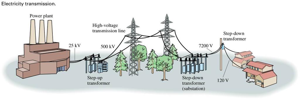
73 Power Transmission
74 Example 26.3 Practical power transmission To provide power to a small city, a power plant generates 40 MW of AC electricity. The power plant is 50 km from the city (a typical distance), and the 100 km of wire used in the transmission line (to the city and back) has a resistance of 7.0 Ω.
75 Example 26.3 Practical power transmission (cont.) a. To provide 40 MW of power at the generator voltage of 25,000 V, what current is required? b. What is the power dissipated in the resistance of the transmission line for this current? c. To provide 40 MW of power at 500,000 V, what current is required? d. What is the power dissipated in the resistance of the transmission line for this higher voltage?
76 Example 26.3 Practical power transmission (cont.) PREPARE We can treat the city and the wires that transmit power to it as a load. All of the voltages are rms values and the power is an average power, so we can find the current to provide a given power and the power dissipated using the relationships in Equation 26.9.
77 Example 26.3 Practical power transmission (cont.) SOLVE a. To provide 40 MW at the generator voltage of 25,000 V, the current is
78 Example 26.3 Practical power transmission (cont.) b. Passing this current through the transmission lines will result in power dissipation in the 7.0 Ω resistance of the wires. We don t know the voltage drop across the wires, but we do know the current and resistance, so we can compute P dissipated in wires = (I rms ) 2 R = (1600 A) 2 (7.0 Ω) = 18 MW This is nearly half the power generated, clearly an unacceptable loss.
79 Example 26.3 Practical power transmission (cont.) c. Increasing the transmission voltage to 500 kv reduces the necessary current: This is a remarkably small current to supply a city. If you use several high-power appliances at one time, you could easily use this much current in your house. But the necessary current for the city can be so small because the voltage is so large.
80 Example 26.3 Practical power transmission (cont.) d. The relatively small current means that the power dissipated in the resistance of the wires will be small as well: P dissipated in wires = (I rms ) 2 R = (80 A) 2 (7.0 Ω) = MW This is only about 0.1% of the power generated, which is quite reasonable.
81 Example 26.3 Practical power transmission (cont.) ASSESS The final result the power dissipated in the wires is dramatically reduced for an increased transmission voltage is just what the example was designed to illustrate.
82 Power Transmission Transmitting electricity at high voltages means a smaller current is required, and therefore the resulting power loss is more manageable than for low voltages (and larger currents). This is why electrical transmission lines run at high voltages. In order to transmit electricity at high voltages, we need to use transformers to increase the voltage, which requires AC electricity. This is why we use AC power even though it is slightly more dangerous than DC power.
Intermediate Physics PHYS102
 Intermediate Physics PHYS102 Dr Richard H. Cyburt Assistant Professor of Physics My office: 402c in the Science Building My phone: (304) 384-6006 My email: rcyburt@concord.edu My webpage: www.concord.edu/rcyburt
Chapter 24. Alternating Current Circuits
 Chapter 24 Alternating Current Circuits Objective of Lecture Generators and Motors Inductance RL Circuits (resistance and inductance) Transformers AC REMINDER: WORK ON THE EXAMPLES Read physics in perspective
Look over Chapter 31 sections 1-4, 6, 8, 9, 10, 11 Examples 1-8. Look over Chapter 21 sections Examples PHYS 2212 PHYS 1112
 PHYS 2212 Look over Chapter 31 sections 1-4, 6, 8, 9, 10, 11 Examples 1-8 PHYS 1112 Look over Chapter 21 sections 11-14 Examples 16-18 Good Things To Know 1) How AC generators work. 2) How to find the
Lecture Presentation Chapter 25 EM Induction and EM Waves
 Lecture Presentation Chapter 25 EM Induction and EM Waves Suggested Videos for Chapter 25 Prelecture Videos Electromagnetic Induction Faraday s Law and Lenz s Law Electromagnetic Waves Class Videos Faraday
CHAPTER 5 Test B Lsn 5-6 to 5-8 TEST REVIEW
 IB PHYSICS Name: Period: Date: DEVIL PHYSICS BADDEST CLASS ON CAMPUS CHAPTER 5 Test B Lsn 5-6 to 5-8 TEST REVIEW 1. This question is about electric circuits. (a) (b) Define (i) (ii) electromotive force
Intermediate Physics PHYS102
 Intermediate Physics PHYS102 Dr Richard H. Cyburt Assistant Professor of Physics My office: 402c in the Science Building My phone: (304) 384-6006 My email: rcyburt@concord.edu My webpage: www.concord.edu/rcyburt
Chapter 25. Electromagnetic Induction
 Lecture 28 Chapter 25 Electromagnetic Induction Electromagnetic Induction Voltage is induced (produced) when the magnetic field changes near a stationary conducting loop or the conductor moves through
PHYS 1444 Section 003 Lecture #19
 PHYS 1444 Section 003 Lecture #19 Monday, Nov. 14, 2005 Electric Generators DC Generator Eddy Currents Transformer Mutual Inductance Today s homework is homework #10, due noon, next Tuesday!! 1 Announcements
12/6/2011. Electromagnetic Induction. Electromagnetic Induction and Electromagnetic Waves. Checking Understanding. Magnetic Flux. Lenz s Law.
 Electromagnetic Induction and Electromagnetic Waves Topics: Electromagnetic induction Lenz s law Faraday s law The nature of electromagnetic waves The spectrum of electromagnetic waves Electromagnetic
Producing Electric Current
 Electromagnetic Induction Working independently in 181, Michael Faraday in Britain and Joseph Henry in the United States both found that moving a loop of wire through a magnetic field caused an electric
CHAPTER 13 REVIEW. Knowledge. Understanding
 CHAPTER 13 REVIEW K/U Knowledge/Understanding T/I Thinking/Investigation C Communication A Application Knowledge For each question, select the best answer from the four alternatives. 1. Which of the following
Chapter 33. Alternating Current Circuits
 Chapter 33 Alternating Current Circuits C HAP T E O UTLI N E 33 1 AC Sources 33 2 esistors in an AC Circuit 33 3 Inductors in an AC Circuit 33 4 Capacitors in an AC Circuit 33 5 The L Series Circuit 33
End-of-Chapter Exercises
 End-of-Chapter Exercises Exercises 1 12 are primarily conceptual questions designed to see whether you understand the main concepts of the chapter. 1. The four areas in Figure 20.34 are in a magnetic field.
PHYS 1442 Section 004 Lecture #15
 PHYS 1442 Section 004 Lecture #15 Monday March 17, 2014 Dr. Andrew Brandt Chapter 21 Generator Transformer Inductance 3/17/2014 1 PHYS 1442-004, Dr. Andrew Brandt Announcements HW8 on Ch 21-22 will be
College Physics B - PHY2054C. Transformers & Electromagnetic Waves 10/08/2014. My Office Hours: Tuesday 10:00 AM - Noon 206 Keen Building
 College - PHY2054C & Electromagnetic Waves 10/08/2014 My Office Hours: Tuesday 10:00 AM - Noon 206 Keen Building PHY2054C Second Mini-Exam next week on Wednesday!! Location: UPL 101, 10:10-11:00 AM Exam
Bakiss Hiyana binti Abu Bakar JKE, POLISAS BHAB
 1 Bakiss Hiyana binti Abu Bakar JKE, POLISAS 1. Explain AC circuit concept and their analysis using AC circuit law. 2. Apply the knowledge of AC circuit in solving problem related to AC electrical circuit.
ELECTROMAGNETIC INDUCTION AND ALTERNATING CURRENT (Assignment)
") ELECTROMAGNETIC INDUCTION AND ALTERNATING CURRENT (Assignment) 1. In an A.C. circuit A ; the current leads the voltage by 30 0 and in circuit B, the current lags behind the voltage by 30 0. What is the
ELECTROMAGNETIC INDUCTION AND ALTERNATING CURRENT (Assignment) 1. In an A.C. circuit A ; the current leads the voltage by 30 0 and in circuit B, the current lags behind the voltage by 30 0. What is the
PHYSICS WORKSHEET CLASS : XII. Topic: Alternating current
 PHYSICS WORKSHEET CLASS : XII Topic: Alternating current 1. What is mean by root mean square value of alternating current? 2. Distinguish between the terms effective value and peak value of an alternating
General Physics (PHY 2140)
") General Physics (PHY 2140) Lecture 11 Electricity and Magnetism AC circuits and EM waves Resonance in a Series RLC circuit Transformers Maxwell, Hertz and EM waves Electromagnetic Waves 6/18/2007 http://www.physics.wayne.edu/~alan/2140website/main.htm
General Physics (PHY 2140) Lecture 11 Electricity and Magnetism AC circuits and EM waves Resonance in a Series RLC circuit Transformers Maxwell, Hertz and EM waves Electromagnetic Waves 6/18/2007 http://www.physics.wayne.edu/~alan/2140website/main.htm
PHYS 1444 Section 501 Lecture #20
 PHYS 1444 Section 501 Lecture #0 Monday, Apr. 17, 006 Transformer Generalized Faraday s Law Inductance Mutual Inductance Self Inductance Inductor Energy Stored in the Magnetic Field 1 Announcements Quiz
Electromagnetic Oscillations and Currents. March 23, 2014 Chapter 30 1
 Electromagnetic Oscillations and Currents March 23, 2014 Chapter 30 1 Driven LC Circuit! The voltage V can be thought of as the projection of the vertical axis of the phasor V m representing the time-varying
15. the power factor of an a.c circuit is.5 what will be the phase difference between voltage and current in this
 1 1. In a series LCR circuit the voltage across inductor, a capacitor and a resistor are 30 V, 30 V and 60 V respectively. What is the phase difference between applied voltage and current in the circuit?
Copper and Electricity: Transformers and. the Grid. Transformers
 PHYSICS Copper and Electricity: Transformers and 16-18 YEARS the Grid Transformers Using transformers We use transformers to change the size of a voltage. We can step the voltage down from a high voltage
Today: Finish Chapter 24. Begin Chapter 25 (Magnetic Induction)
") Today: Finish Chapter 24 Begin Chapter 25 (Magnetic Induction) Next Homework posted, due next Fri Dec 11 Electromagnetic Induction Voltage can be induced (created) by a changing magnetic field. C.f. last
Today: Finish Chapter 24 Begin Chapter 25 (Magnetic Induction) Next Homework posted, due next Fri Dec 11 Electromagnetic Induction Voltage can be induced (created) by a changing magnetic field. C.f. last
I p = V s = N s I s V p N p
 UNIT G485 Module 1 5.1.3 Electromagnetism 11 For an IDEAL transformer : electrical power input = electrical power output to the primary coil from the secondary coil Primary current x primary voltage =
Physics for Scientists & Engineers 2 2 = 1 LC. Review ( ) Review (2) Review (3) e! Rt. cos "t + # ( ) q = q max. Spring Semester 2005 Lecture 30 U E
 Review (2) Review (3) e! Rt. cos t + # ( ) q = q max. Spring Semester 2005 Lecture 30 U E") Review hysics for Scientists & Engineers Spring Semester 005 Lecture 30! If we have a single loop RLC circuit, the charge in the circuit as a function of time is given by! Where q = q max e! Rt L cos "t
Review hysics for Scientists & Engineers Spring Semester 005 Lecture 30! If we have a single loop RLC circuit, the charge in the circuit as a function of time is given by! Where q = q max e! Rt L cos "t
PHYS 1441 Section 001 Lecture #22 Wednesday, Nov. 29, 2017
 PHYS 1441 Section 001 Lecture #22 Chapter 29:EM Induction & Faraday s Law Transformer Electric Field Due to Changing Magnetic Flux Chapter 30: Inductance Mutual and Self Inductance Energy Stored in Magnetic
AP Physics C. Alternating Current. Chapter Problems. Sources of Alternating EMF
 AP Physics C Alternating Current Chapter Problems Sources of Alternating EMF 1. A 10 cm diameter loop of wire is oriented perpendicular to a 2.5 T magnetic field. What is the magnetic flux through the
Chapter 23 Circuits. Chapter Goal: To understand the fundamental physical principles that govern electric circuits. Slide 23-1
 Chapter 23 Circuits Chapter Goal: To understand the fundamental physical principles that govern electric circuits. Slide 23-1 Chapter 23 Preview Looking Ahead: Analyzing Circuits Practical circuits consist
CHAPTER 5 CONCEPTS OF ALTERNATING CURRENT
 CHAPTER 5 CONCEPTS OF ALTERNATING CURRENT INTRODUCTION Thus far this text has dealt with direct current (DC); that is, current that does not change direction. However, a coil rotating in a magnetic field
In this lecture. Electromagnetism. Electromagnetism. Oersted s Experiment. Electricity & magnetism are different aspects of the same basic phenomenon:
 In this lecture Electromagnetism Electromagnetic Effect Electromagnets Electromechanical Devices Transformers Electromagnetic Effect Electricity & magnetism are different aspects of the same basic phenomenon:
Physics review Practice problems
 Physics review Practice problems 1. A double slit interference pattern is observed on a screen 2.0 m behind 2 slits spaced 0.5 mm apart. From the center of one particular fringe to 9 th bright fringe is
DEVIL PHYSICS THE BADDEST CLASS ON CAMPUS IB PHYSICS
 DEVIL PHYSICS THE BADDEST CLASS ON CAMPUS IB PHYSICS TSOKOS LSN 11-2 TRANSMISSION OF POWER Essential Idea: Generation and transmission of alternating current (ac) electricity has transformed the world.
An induced emf is the negative of a changing magnetic field. Similarly, a self-induced emf would be found by
 This is a study guide for Exam 4. You are expected to understand and be able to answer mathematical questions on the following topics. Chapter 32 Self-Induction and Induction While a battery creates an
Generators and Alternating Current
 Generators and Alternating Current If one end of a magnet is moved in and out of a coil of wire, the induced voltage alternates in direction. The greater the frequency with which the magnet moves in and
Chapter 33. Alternating Current Circuits
 Chapter 33 Alternating Current Circuits Alternating Current Circuits Electrical appliances in the house use alternating current (AC) circuits. If an AC source applies an alternating voltage to a series
37 Electromagnetic Induction. Magnetism can produce electric current, and electric current can produce magnetism.
 Magnetism can produce electric current, and electric current can produce magnetism. In 1831, two physicists, Michael Faraday in England and Joseph Henry in the United States, independently discovered that
Magnetism can produce electric current can. produce magnetism Electromagnetic Induction
 Magnetism can produce electric current, and electric current can produce magnetism. In 1831, two physicists, Michael Faraday in England and Joseph Henry in the United States, independently discovered that
Electrical Theory. Power Principles and Phase Angle. PJM State & Member Training Dept. PJM /22/2018
 Electrical Theory Power Principles and Phase Angle PJM State & Member Training Dept. PJM 2018 Objectives At the end of this presentation the learner will be able to: Identify the characteristics of Sine
The topics in this unit are:
 The topics in this unit are: 1 Static electricity 2 Repulsion and attraction 3 Electric circuits 4 Circuit symbols 5 Currents 6 Resistance 7 Thermistors and light dependent resistors 8 Series circuits
Lesson 22A Alternating Current & Transformers
 Physics 30 Lesson 22A Alternating Current & Transformers I Alternating Current Many electric circuits use electrochemical cells (batteries) which involve direct current (DC). In dc electric power, the
Note on Posted Slides
 Note on Posted Slides These are the slides that I intended to show in class on Tue. Mar. 25, 2014. They contain important ideas and questions from your reading. Due to time constraints, I was probably
E) all of the above E) 1.9 T
 all of the above E) 1.9 T") 1. The figure shows a uniform magnetic field that is normal to the plane of a conducting loop, which has a resistance R. Which one of the following changes will cause an induced current to flow through
1. The figure shows a uniform magnetic field that is normal to the plane of a conducting loop, which has a resistance R. Which one of the following changes will cause an induced current to flow through
Experiment 9: AC circuits
 Experiment 9: AC circuits Nate Saffold nas2173@columbia.edu Office Hour: Mondays, 5:30PM-6:30PM @ Pupin 1216 INTRO TO EXPERIMENTAL PHYS-LAB 1493/1494/2699 Introduction Last week (RC circuit): This week:
AC Circuits. Nikola Tesla
 AC Circuits Nikola Tesla 1856-1943 Mar 26, 2012 Alternating Current Circuits Electrical appliances in the house use alternating current (AC) circuits. If an AC source applies an alternating voltage of
Chapter 20 Electric Circuits
 Chapter 20 Electric Circuits 1 20.1 Electromotive Force and Current In an electric circuit, an energy source and an energy consuming device are connected by conducting wires through which electric charges
AP Physics Electricity and Magnetism #7 Inductance
 Name Period AP Physics Electricity and Magnetism #7 Inductance Dr. Campbell 1. Do problems Exercise B page 589 and problem 2, 3, 8, 9 page 610-1. Answers at the end of the packet. 2. A 20-turn wire coil
10 Electromagnetic Interactions
 Lab 10 Electromagnetic Interactions What You Need To Know: The Physics Electricity and magnetism are intrinsically linked and not separate phenomena. A changing magnetic field can create an electric field
y 2irfCj Resonance in AC Circuits Summary v v The rms current in an LRC series circuit is given by (see Eqs , 21-15, 21-llb, and 21-12b):
:") -* Resonance in AC Circuits The rms current in an LRC series circuit is given by (see Eqs. 21-14, 21-15, 21-llb, and 21-12b): -'rms v v
-* Resonance in AC Circuits The rms current in an LRC series circuit is given by (see Eqs. 21-14, 21-15, 21-llb, and 21-12b): -'rms v v
Class XII Chapter 7 Alternating Current Physics
 Question 7.1: A 100 Ω resistor is connected to a 220 V, 50 Hz ac supply. (a) What is the rms value of current in the circuit? (b) What is the net power consumed over a full cycle? Resistance of the resistor,
4. The circuit in an appliance is 3A and the voltage difference is 120V. How much power is being supplied to the appliance?
 1 Name: Date: / / Period: Formulas I = V/R P = I V E = P t 1. A circuit has a resistance of 4Ω. What voltage difference will cause a current of 1.4A to flow in the 2. How many amperes of current will flow
AC generator theory. Resources and methods for learning about these subjects (list a few here, in preparation for your research):
:") AC generator theory This worksheet and all related files are licensed under the Creative Commons Attribution License, version 1.0. To view a copy of this license, visit http://creativecommons.org/licenses/by/1.0/,
AC generator theory This worksheet and all related files are licensed under the Creative Commons Attribution License, version 1.0. To view a copy of this license, visit http://creativecommons.org/licenses/by/1.0/,
Electromagnetism - Grade 11
 OpenStax-CNX module: m32837 1 Electromagnetism - Grade 11 Rory Adams Free High School Science Texts Project Mark Horner Heather Williams This work is produced by OpenStax-CNX and licensed under the Creative
Chapter 20. Circuits. q I = t. (a) (b) (c) Energy Charge
 (b) (c) Energy Charge") Chapter 0 n an electric circuit, an energy source and an energy consuming device are connected by conducting wires through which electric charges move. Circuits Within a battery, a chemical reaction occurs
Chapter 0 n an electric circuit, an energy source and an energy consuming device are connected by conducting wires through which electric charges move. Circuits Within a battery, a chemical reaction occurs
Electromagnetic Induction
 Chapter 16 Electromagnetic Induction In This Chapter: Electromagnetic Induction Faraday s Law Lenz s Law The Transformer Self-Inductance Inductors in Combination Energy of a Current-Carrying Inductor Electromagnetic
Alternating Current. Slide 1 / 69. Slide 2 / 69. Slide 3 / 69. Topics to be covered. Sources of Alternating EMF. Sources of alternating EMF
 Slide 1 / 69 lternating urrent Sources of alternating EMF Transformers ircuits and Impedance Topics to be covered Slide 2 / 69 LR Series ircuits Resonance in ircuit Oscillations Sources of lternating EMF
Alternating Current. Slide 2 / 69. Slide 1 / 69. Slide 3 / 69. Slide 4 / 69. Slide 6 / 69. Slide 5 / 69. Topics to be covered
 Slide 1 / 69 lternating urrent Sources of alternating EMF ircuits and Impedance Slide 2 / 69 Topics to be covered LR Series ircuits Resonance in ircuit Oscillations Slide 3 / 69 Sources of lternating EMF
13 th Asian Physics Olympiad India Experimental Competition Wednesday, 2 nd May 2012
 13 th Asian Physics Olympiad India Experimental Competition Wednesday, nd May 01 Please first read the following instructions carefully: 1. The time available is ½ hours for each of the two experimental
EE 42/100 Lecture 16: Inductance. Rev B 3/15/2010 (8:55 PM) Prof. Ali M. Niknejad
 Prof. Ali M. Niknejad") A. M. Niknejad University of California, Berkeley EE 100 / 42 Lecture 16 p. 1/23 EE 42/100 Lecture 16: Inductance ELECTRONICS Rev B 3/15/2010 (8:55 PM) Prof. Ali M. Niknejad University of California, Berkeley
A. M. Niknejad University of California, Berkeley EE 100 / 42 Lecture 16 p. 1/23 EE 42/100 Lecture 16: Inductance ELECTRONICS Rev B 3/15/2010 (8:55 PM) Prof. Ali M. Niknejad University of California, Berkeley
CHAPTER 8: ELECTROMAGNETISM
 CHAPTER 8: ELECTROMAGNETISM 8.1: MAGNETIC EFFECT OF A CURRENT-CARRYING CONDUCTOR Electromagnets 1. Conductor is a material that can flow.. 2. Electromagnetism is the study of the relationship between.and..
Lecture 3.10 ELECTRICITY Alternating current Electrical safety
 Lecture 3.1 ELECTRCTY Alternating current Electrical safety Alternating Current (ac) Batteries are a source of steady or direct voltage. Current in a circuit powered by a battery is also steady and is
Electric Current - 1 v Goodman & Zavorotniy
 Chapter Problems Electric Current Classwork 1. If 560 C of electric charge passed through a light bulb in 8 min; what was the magnitude of the average electric current passing through the bulb? 2. If the
Example 25 1: A total charge of 25 C passes through a wire every 5 seconds. What is the current in this wire?
 1 PHYS:100 LECTUE 5 ELECTICITY AND MAGNETISM (3) This lecture is devoted entirely to the very practical topic of electric circuits. This discussion will include concepts that everyone should be aware of,
Inductance in DC Circuits
 Inductance in DC Circuits Anurag Srivastava Concept: Inductance is characterized by the behavior of a coil of wire in resisting any change of electric current through the coil. Arising from Faraday's law,
Physics 202 Midterm Exam 3 Nov 30th, 2011
 Physics 202 Midterm Exam 3 Nov 30th, 2011 Name: Student ID: Section: TA (please circle): Daniel Crow Scott Douglas Yutao Gong Taylor Klaus Aaron Levine Andrew Loveridge Jason Milhone Hojin Yoo Instructions:
12.2 ALTERNATING CURRENT 12.3 TRANSMISSION OF ELECTRICAL POWER HW/Study Packet
 12.2 ALTERNATING CURRENT 12.3 TRANSMISSION OF ELECTRICAL POWER HW/Study Packet Required: READ Tsokos, pp 360-365 Hamper pp 209-219 HL Supplemental: Cutnell and Johnson, pp 696-707 Giancoli, pp 592-597
1. A sinusoidal ac power supply has rms voltage V and supplies rms current I. What is the maximum instantaneous power delivered?
 1. A sinusoidal ac power supply has rms voltage V and supplies rms current I. What is the maximum instantaneous power delivered? A. VI B. VI C. VI D. VI. An alternating current supply of negligible internal
total j = BA, [1] = j [2] total
![total j = BA, [1] = j [2] total](/thumbs/85/91692343.jpg "total j = BA, [1] = j [2] total") Name: S.N.: Experiment 2 INDUCTANCE AND LR CIRCUITS SECTION: PARTNER: DATE: Objectives Estimate the inductance of the solenoid used for this experiment from the formula for a very long, thin, tightly wound
Name: S.N.: Experiment 2 INDUCTANCE AND LR CIRCUITS SECTION: PARTNER: DATE: Objectives Estimate the inductance of the solenoid used for this experiment from the formula for a very long, thin, tightly wound
1. The coulomb is a unit of. A. charge B. voltage C. energy D. capacitance E. current. 2. The following is not true about voltage:
 BioE 1310 - Review 1 - DC 1/16/2017 Instructions: On the Answer Sheet, enter your 2-digit ID number (with a leading 0 if needed) in the boxes of the ID section. Fill in the corresponding numbered circles.
Alternating current circuits- Series RLC circuits
 FISI30 Física Universitaria II Professor J.. ersosimo hapter 8 Alternating current circuits- Series circuits 8- Introduction A loop rotated in a magnetic field produces a sinusoidal voltage and current.
Ac fundamentals and AC CIRCUITS. Q1. Explain and derive an expression for generation of AC quantity.
 Ac fundamentals and AC CIRCUITS Q1. Explain and derive an expression for generation of AC quantity. According to Faradays law of electromagnetic induction when a conductor is moving within a magnetic field,
PH213 Chapter 26 solutions
 PH213 Chapter 26 solutions 26.6. IDENTIFY: The potential drop is the same across the resistors in parallel, and the current into the parallel combination is the same as the current through the 45.0-Ω resistor.
Lab E2: B-field of a Solenoid. In the case that the B-field is uniform and perpendicular to the area, (1) reduces to
 reduces to") E2.1 Lab E2: B-field of a Solenoid In this lab, we will explore the magnetic field created by a solenoid. First, we must review some basic electromagnetic theory. The magnetic flux over some area A is
E2.1 Lab E2: B-field of a Solenoid In this lab, we will explore the magnetic field created by a solenoid. First, we must review some basic electromagnetic theory. The magnetic flux over some area A is
13. Magnetically Coupled Circuits
 13. Magnetically Coupled Circuits The change in the current flowing through an inductor induces (creates) a voltage in the conductor itself (self-inductance) and in any nearby conductors (mutual inductance)
Chapter 13. Electric Circuits
 Chapter 13 Electric Circuits Lower Potential Battery (EMF - E) - + Higher Potential Bulb (Resistor) Wires (No Change in Potential) EMF (Voltage Source) _ + Resistor Working Circuits For a circuit to work,
Solution: All electromagnetic waves in vacuum, regardless of their wavelength or frequency, travel at the speed of light, c.
 1. Two electromagnetic waves travel through empty space. Wave A as a wavelength of 700 nm (red light), while Wave B has a wavelength of 400 nm (blue light). Which statement is true? A) Wave A travels faster
In an unmagnetized piece of iron, the atoms are arranged in domains. In each domain the atoms are aligned, but the domains themselves are random.
 4/7 Properties of the Magnetic Force 1. Perpendicular to the field and velocity. 2. If the velocity and field are parallel, the force is zero. 3. Roughly (field and vel perp), the force is the product
University Physics II Dr. Michael Zelin Thursday 2:00pm 3:50pm. Faraday s Law. Group 9 Braden Reed Shawn Newton Sean-Michael Stubbs
 University Physics II Dr. Michael Zelin Thursday 2:00pm 3:50pm Faraday s Law by Group 9 Braden Reed Shawn Newton Sean-Michael Stubbs Lab Performed October 27, 2016 Report Submitted November 3, 2016 Objective:
PY106 Assignment 7 ( )
") 1 of 7 3/13/2010 8:47 AM PY106 Assignment 7 (1190319) Current Score: 0/20 Due: Tue Mar 23 2010 10:15 PM EDT Question Points 1 2 3 4 5 6 7 0/3 0/4 0/2 0/2 0/5 0/2 0/2 Total 0/20 Description This assignment
1 of 7 3/13/2010 8:47 AM PY106 Assignment 7 (1190319) Current Score: 0/20 Due: Tue Mar 23 2010 10:15 PM EDT Question Points 1 2 3 4 5 6 7 0/3 0/4 0/2 0/2 0/5 0/2 0/2 Total 0/20 Description This assignment
Chapter Moving Charges and Magnetism
 100 Chapter Moving Charges and Magnetism 1. The power factor of an AC circuit having resistance (R) and inductance (L) connected in series and an angular velocity ω is [2013] 2. [2002] zero RvB vbl/r vbl
Walchand Institute of Technology. Basic Electrical and Electronics Engineering. Transformer
 Walchand Institute of Technology Basic Electrical and Electronics Engineering Transformer 1. What is transformer? explain working principle of transformer. Electrical power transformer is a static device
1. If the flux associated with a coil varies at the rate of 1 weber/min,the induced emf is
 1. f the flux associated with a coil varies at the rate of 1 weber/min,the induced emf is 1 1. 1V 2. V 60 3. 60V 4. Zero 2. Lenz s law is the consequence of the law of conservation of 1. Charge 2. Mass
Electromagnetic Induction. Chapter 37
 Electromagnetic Induction Chapter 37 Wire moves past magnetic field Field moves past wire a voltage is produced. Electromagnetic induction Magnetism is not the source of voltage the wire is not the source
Name: Lab Partner: Section: The purpose of this lab is to study induction. Faraday s law of induction and Lenz s law will be explored. B = B A (8.
 Chapter 8 Induction - Faraday s Law Name: Lab Partner: Section: 8.1 Purpose The purpose of this lab is to study induction. Faraday s law of induction and Lenz s law will be explored. 8.2 Introduction It
not to be republished NCERT ALTERNATING CURRENT Chapter Seven MCQ 1
 hapter Seven ALTERNATING URRENT MQ 1 7.1 If the rms current in a 50 Hz ac circuit is 5 A, the value of the current 1/300 seconds after its value becomes zero is (a) 5 2 A (b) 5 3/2 A (c) 5/6 A (d) 5/ 2
Faraday Laws of Electromagnetic Induction CLIL LESSON
 Faraday Laws of Electromagnetic Induction CLIL LESSON Experimental trials Michael Faraday-1931 This law shows the relationship between electric circuit and magnetic field A coil is connected to a galvanometer
Electrical Engineering / Electromagnetics
 Electrical Engineering / Electromagnetics. Plot voltage versus time and current versus time for the circuit with the following substitutions: A. esistor B. Capacitor C. Inductor t = 0 A/B/C A. I t t B.
Resistance and Ohm s Law
 Resistance and Ohm s Law Textbook pages 290 301 Section 8.3 Summary Before You Read Do you think electrons can move through all conducting substances equally well? Give your reasons why or why not on the
Chapter 21. Alternating Current Circuits and Electromagnetic Waves
 Chapter 21 Alternating Current Circuits and Electromagnetic Waves AC Circuit An AC circuit consists of a combination of circuit elements and an AC generator or source The output of an AC generator is sinusoidal
A piece of wire of resistance R is cut into five equal parts. These parts are then connected in
 Page 221»Exercise» Question 1: A piece of wire of resistance R is cut into five equal parts. These parts are then connected in parallel. If the equivalent resistance of this combination is R', then the
AP Physics - Problem Drill 14: Electric Circuits
 AP Physics - Problem Drill 14: Electric Circuits No. 1 of 10 1. Identify the four electric circuit symbols. (A) 1. AC power 2. Battery 3. Light Bulb 4. Resistor (B) 1. Ammeter 2. Resistor 3. AC Power 4.
Exam 3 Review Session
 Exam 3 Review Session I will hold a review for Exam 3 which covers Chapters 27, 28, 29 and 30, on Wednesday November 7 th at 7:15pm in MPHY 205. Exam 3 will be given in class on Thursday, November 8 th.
Electromagnetic Induction - A
 Electromagnetic Induction - A APPARATUS 1. Two 225-turn coils 2. Table Galvanometer 3. Rheostat 4. Iron and aluminum rods 5. Large circular loop mounted on board 6. AC ammeter 7. Variac 8. Search coil
Faraday's Law. Objective: In today's experiment you will investigate electromagnetic induction and determine the factors that affect it.
 Faraday's Law 1 Objective: In today's experiment you will investigate electromagnetic induction and determine the factors that affect it. Theory: The phenomenon of electromagnetic induction was first studied
Transformers. Dr. Gamal Sowilam
 Transformers Dr. Gamal Sowilam OBJECTIVES Become familiar with the flux linkages that exist between the coils of a transformer and how the voltages across the primary and secondary are established. Understand
(c) In the process of part (b), must energy be supplied to the electron, or is energy released?
 In the process of part (b), must energy be supplied to the electron, or is energy released?") (1) A capacitor, as shown, has plates of dimensions 10a by 10a, and plate separation a. The field inside is uniform, and has magnitude 120 N/C. The constant a equals 4.5 cm. (a) What amount of charge is
(1) A capacitor, as shown, has plates of dimensions 10a by 10a, and plate separation a. The field inside is uniform, and has magnitude 120 N/C. The constant a equals 4.5 cm. (a) What amount of charge is
Questions on Electromagnetism
 Questions on Electromagnetism 1. The dynamo torch, Figure 1, is operated by successive squeezes of the handle. These cause a permanent magnet to rotate within a fixed coil of wires, see Figure 2. Harder
EC-5 MAGNETIC INDUCTION
 EC-5 MAGNETIC INDUCTION If an object is placed in a changing magnetic field, or if an object is moving in a non-uniform magnetic field in such a way that it experiences a changing magnetic field, a voltage
Chapt ha e pt r e r 11 Inductors
 Chapter 11 Inductors The Basic Inductor When a length of wire is formed onto a coil, it becomes a basic inductor Magnetic lines of force around each loop in the winding of the coil effectively add to the
Chapter 11. Alternating Current
 Unit-2 ECE131 BEEE Chapter 11 Alternating Current Objectives After completing this chapter, you will be able to: Describe how an AC voltage is produced with an AC generator (alternator) Define alternation,