Intermediate Physics PHYS102
|
|
|
- Blaise Townsend
- 5 years ago
- Views:
Transcription


1 Intermediate Physics PHYS102
2 Dr Richard H. Cyburt Assistant Professor of Physics My office: 402c in the Science Building My phone: (304) My My webpage: In person or is the best way to get a hold of me. PHYS102
3 My Office Hours TWR 9:30-11:00am W 4:00-5:00pm Meetings may also be arranged at other times, by appointment PHYS102
4 Problem Solving Sections I would like to have hour-long sections for working through problems. This would be an extra component to the course and count towards extra credit TR 1-2 pm WF am S308 If you can t make these, you can still pick up the problem worksheet. PHYS102
5 Midterm 2 Thursday, March 2 during class 8-9:15 Chapters , Lectures 7-13 Allowed one half sheet (8.5x11) piece of paper w/ notes/formuli Calculator pencil or blue/black pen Review, Wednesday, March 1 7-9pm Bring questions!!! PHYS102
6 Intermediate Physics PHYS102


7 Douglas Adams Hitchhiker s Guide to the Galaxy PHYS102
8 In class!! PHYS102
9 This lecture will help you understand: Transformers Household Electricity Biological Effects and Electrical Safety PHYS102
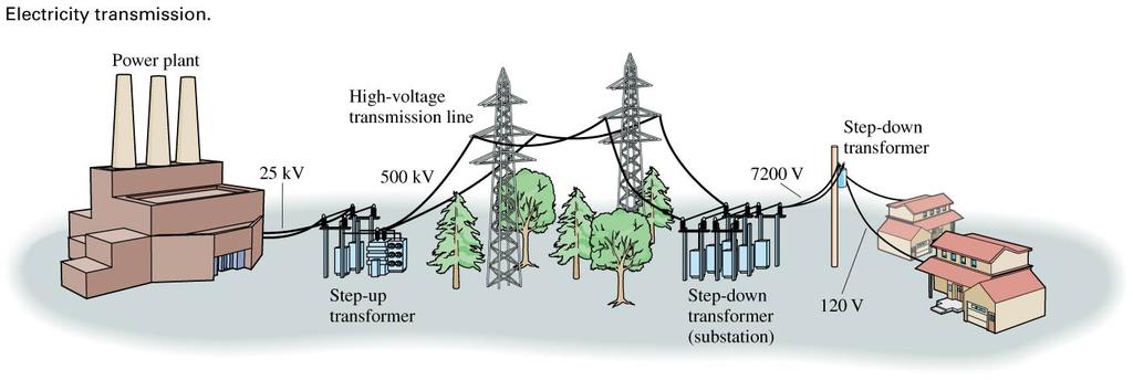
10 Power Transmission
11 Example 26.3 Practical power transmission To provide power to a small city, a power plant generates 40 MW of AC electricity. The power plant is 50 km from the city (a typical distance), and the 100 km of wire used in the transmission line (to the city and back) has a resistance of 7.0 Ω.
12 Example 26.3 Practical power transmission (cont.) a. To provide 40 MW of power at the generator voltage of 25,000 V, what current is required? b. What is the power dissipated in the resistance of the transmission line for this current? c. To provide 40 MW of power at 500,000 V, what current is required? d. What is the power dissipated in the resistance of the transmission line for this higher voltage?
13 Example 26.3 Practical power transmission (cont.) PREPARE We can treat the city and the wires that transmit power to it as a load. All of the voltages are rms values and the power is an average power, so we can find the current to provide a given power and the power dissipated using the relationships in Equation 26.9.
14 Example 26.3 Practical power transmission (cont.) SOLVE a. To provide 40 MW at the generator voltage of 25,000 V, the current is
15 Example 26.3 Practical power transmission (cont.) b. Passing this current through the transmission lines will result in power dissipation in the 7.0 Ω resistance of the wires. We don t know the voltage drop across the wires, but we do know the current and resistance, so we can compute P dissipated in wires = (I rms ) 2 R = (1600 A) 2 (7.0 Ω) = 18 MW This is nearly half the power generated, clearly an unacceptable loss.
16 Example 26.3 Practical power transmission (cont.) c. Increasing the transmission voltage to 500 kv reduces the necessary current: This is a remarkably small current to supply a city. If you use several high-power appliances at one time, you could easily use this much current in your house. But the necessary current for the city can be so small because the voltage is so large.
17 Example 26.3 Practical power transmission (cont.) d. The relatively small current means that the power dissipated in the resistance of the wires will be small as well: P dissipated in wires = (I rms ) 2 R = (80 A) 2 (7.0 Ω) = MW This is only about 0.1% of the power generated, which is quite reasonable.
18 Example 26.3 Practical power transmission (cont.) ASSESS The final result the power dissipated in the wires is dramatically reduced for an increased transmission voltage is just what the example was designed to illustrate.
19 Power Transmission Transmitting electricity at high voltages means a smaller current is required, and therefore the resulting power loss is more manageable than for low voltages (and larger currents). This is why electrical transmission lines run at high voltages. In order to transmit electricity at high voltages, we need to use transformers to increase the voltage, which requires AC electricity. This is why we use AC power even though it is slightly more dangerous than DC power.
20 Section 26.3 Household Electricity
21 Household Electricity For single circuits, we have only dealt with the potential difference. When you want to connect different circuits together, like a computer monitor to the computer itself, the connected circuits need a common reference point for the potential. This is why we have an electric ground.
22 Getting Grounded The earth itself is a conductor. If we connect one point from two different circuits to the earth with ideal wires, then both circuits have a common reference point. In practice, we could call the potential of the earth V earth = 0 V.
23 Getting Grounded A circuit connected to the earth is said to be grounded. Under normal circumstances, the ground connection does not carry any current because it is not part of the complete circuit, so it does not alter the behavior of the circuit.
24 Electric Outlets Are Grounded Parallel Circuits The outlets in your house are connected in parallel. Electricity provided by the power company is transmitted to outlets through wires in your walls. One terminal of the electric supply is grounded; we call it the neutral side. The other has varying potential; the hot side. Each outlet has two slots, one connected to each side.
25 Electric Outlets Are Grounded Parallel Circuits When you insert a plug into an electrical outlet, the prongs connect to the two terminals of the electric supply. The device you ve plugged in completes the circuit, the potential difference across the device leads to a current, and the device turns on.

26 Electric Outlets Are Grounded Parallel Circuits
27 Electric Outlets Are Grounded Parallel Circuits The multiple outlets in a room are connected in parallel so that each works while the others are not being used. If multiple outlets are used, then the total current in the circuit increases. The wires in your house are not ideal; they have small resistances and can heat up and cause a fire when there is too much current. A circuit breaker limits the current in each circuit. If an ammeter measures too much current, it sends a signal to open the switch to disconnect the circuit.
28 Electric Outlets Are Grounded Parallel Circuits When a plug is connected to the outlet and you turn off the device, the switch disconnects the hot wire, not the neutral wire. The device is then grounded, and thus safe, when switched off. The round hole in an electric outlet is a second ground connection. If a device has a metal case, and a wire comes loose in the device and contacts the case, a person then touching the case can get shocked. If the device with the metal case is grounded, the potential is 0 and therefore always safe to touch. A hot wire touching a grounded case would create a large circuit that would trip the circuit breaker, which would disconnect the wire.
29 Example 26.4 Will the circuit breaker open? A circuit in a student s room has a 15 A circuit breaker. One evening, she plugs in a computer (240 W), a lamp (with two 60 W bulbs), and a space heater (1200 W). Will this be enough to trip the circuit breaker?
30 Example 26.4 Will the circuit breaker open? (cont.) PREPARE We start by sketching the circuit, as in FIGURE Because the three devices are in the same circuit, they are connected in parallel. We can model each of them as a resistor.
31 Example 26.4 Will the circuit breaker open? (cont.) SOLVE The current in the circuit is the sum of the currents in the individual devices: (I total ) rms = (I computer ) rms + (I lamp ) rm s + (I heater ) rms
32 Example 26.4 Will the circuit breaker open? (cont.) Equation 26.9 gives the power as the rms current times the rms voltage, so the current in each device is the power divided by the rms voltage: This is almost but not quite enough to trip the circuit breaker.
33 Example 26.4 Will the circuit breaker open? (cont.) ASSESS Generally all of the outlets in one room (and perhaps the lights as well) are on the same circuit. You have quite possibly used electric devices with this much total power in one room without problems, so this result seems reasonable.
34 Kilowatt Hours Kilowatt hours is the unit of energy the electric power companies use to measure the energy used each month at a home. The conversion between kilowatt hours and joules is 1 kwh = ( W)(3600 s) = J
35 Example 26.5 Computing the cost of electric energy A typical electric space heater draws an rms current of 12.5 A on its highest setting. If electricity costs 12 per kilowatt hour (an approximate national average), how much does it cost to run the heater for 2 hours? SOLVE The power dissipated by the heater is P = V rms I rms = (120 V)(12.5 A) = 1500 W = 1.5 kw In 2 hours, the energy used is (1.5 kw)(2.0 h) = 3.0 kwh. At 12 per kwh, the cost is 36.
36 Example Problem The following devices are plugged into outlets on the same 120 V circuit in a house. This circuit is protected with a 15 A circuit breaker. Does the circuit breaker blow? Device Computer Heater Lamp Stereo Power 250 W 900 W 100 W 120 W
37 Section 26.4 Biological Effects and Electrical Safety
38 Biological Effects and Electrical Safety The relative safety of electricity is not governed by the voltage but by the current. Current the flow of charges through the body is what produces physiological effects and damage because it mimics nerve impulses and causes muscles to involuntarily contract.

39 Biological Effects and Electrical Safety A girl touching a Van de Graaff generator is not in danger of shock because she is standing on an insulating surface. The high resistance of the platform means little current is passing through her to the ground. Even if she touches a grounded object, the current is modest because the charge of the generator is small.
40 Biological Effects and Electrical Safety
41 Biological Effects and Electrical Safety To calculate currents through the body, we model the body as several connected resistors. The skin has a fairly high resistance, but the interior of the body has a low resistance due to its high saltwater content.
42 Biological Effects and Electrical Safety
43 Example 26.6 Is the worker in danger? A worker in a plant grabs a bare wire that he does not know is connected to a 480 V AC supply. His other hand is holding a grounded metal railing. The skin resistance of each of his hands, in full contact with a conductor, is 2200 Ω. He will receive a shock. Is it large enough to be dangerous?

44 Example 26.6 Is the worker in danger? (cont.) PREPARE We can draw a circuit model for this situation as in FIGURE 26.14a; the worker s body completes a circuit between two points at a potential difference of 480 V. The current will depend on this potential difference and the resistance of his body, including the resistance of the skin.
45 Example 26.6 Is the worker in danger? (cont.) SOLVE Following the model of Figure 26.13, the current path goes through the skin of one hand, up one arm, across the torso, down the other arm, and through the skin of the other hand, as in FIGURE 26.14b. The equivalent resistance of the series combination is 5050 Ω, so the AC current through his body is
46 Example 26.6 Is the worker in danger? (cont.) From Table 26.1 we see that this is a very dangerous, possibly fatal, current. ASSESS The voltage is high and the resistance relatively low, so it s no surprise to find a dangerous level of current.

47 Biological Effects and Electrical Safety The resistance of preventative clothing, like in work boots, is higher than that of the skin; it provides protection from high currents and therefore electric shock.
48 GFI Circuits Ground fault interrupter outlets (GFI) have a built-in sensing circuit that compares the currents in the hot and neutral wires. The current in these wires should be the same. If the sensor detects that some current from the hot wire is finding an alternative path to the ground, such as through a person, the GFI disconnects the circuit.

49 Try It Yourself: Testing GFI Circuits You can test a GFI circuit by pressing the black Test button. This creates an electrical connection between the hot wire and the ground connection, so the currents in the hot and neutral wires will not be equal. You should hear a click as the circuit disconnects. You can then reset the outlet by pressing the red button. If an outlet does not respond like this, it should be replaced.
50 Example Problem Suppose a person is standing, barefoot, on wet ground. The resistance of the skin on each foot is 300 Ω. He now grabs an improperly wired device with His right hand establishing a connection to the hot wire of the electric supply at 120V. His hand is a bit sweaty, so the resistance of the skin is only 1.2 kω. A. What current will flow through the person s body? B. Will this be large enough for the person to feel? Large enough to be dangerous?
Intermediate Physics PHYS102
 Intermediate Physics PHYS102 Dr Richard H. Cyburt Assistant Professor of Physics My office: 402c in the Science Building My phone: (304) 384-6006 My email: rcyburt@concord.edu My webpage: www.concord.edu/rcyburt
Chapter 13. Electric Circuits
 Chapter 13 Electric Circuits Lower Potential Battery (EMF - E) - + Higher Potential Bulb (Resistor) Wires (No Change in Potential) EMF (Voltage Source) _ + Resistor Working Circuits For a circuit to work,
Get the 22.2 Superconductor notes (LAST NOTES!!) from the brown table. Jun 7 10:01 AM
 from the brown table. Jun 7 10:01 AM") No clickers & yes calculators. Get the 22.2 Superconductor notes (LAST NOTES!!) from the brown table. Have out pg. 600 17-21 all Jun 7 10:01 AM 22.2 Superconductors A superconductor is a material with
No clickers & yes calculators. Get the 22.2 Superconductor notes (LAST NOTES!!) from the brown table. Have out pg. 600 17-21 all Jun 7 10:01 AM 22.2 Superconductors A superconductor is a material with
1 V = IR P = IV R eq. 1 R i. = R i. = R eq. V = Energy Q. I = Q t
 Chapters 34 & 35: Electric Circuits NAME: Text: Chapter 34 Chapter 35 Think and Explain: 1-3, 6-8, 10 Think and Explain: 1-10 Think and Solve: 1-6 Think and Solve: 1-4 Vocabulary: Ohm s Law, resistance,
Exam 2. Name: Class: Date: Multiple Choice Identify the choice that best completes the statement or answers the question.
 Name: Class: Date: Exam 2 Multiple Choice Identify the choice that best completes the statement or answers the question. 1. For this circuit, which of these equations is correct? a. 80-1I 2-20I 2-30I 1
A battery transforms chemical energy into electrical energy. Chemical reactions within the cell create a potential difference between the terminals
 D.C Electricity Volta discovered that electricity could be created if dissimilar metals were connected by a conductive solution called an electrolyte. This is a simple electric cell. The Electric Battery
National Physics. Electricity and Energy Homework. Section 2 Electrical Power
 National Physics Electricity and Energy Homework Section 2 Electrical Power Homework 1 : Energy Changes and Power 1. Appliances convert electrical energy into other forms of energy. State the useful energy
Module Title: Electrical Installation II Laboratory Sheet:
 Vocational Training Council Hong Kong Institute of Vocational Education Department of Engineering Module Title: Electrical Installation II Laboratory Sheet: Student name: Course / Year: Subject: Date:
Date Period Name. For each description on the left, write the letter of the matching item.
 Date Period Name CHAPTER 23 Study Guide Series and Parallel Circuits Vocabulary Review For each description on the left, write the letter of the matching item. Section 23.1 1. a circuit in which all current
Electricity. AQA Physics topic 2
 Electricity AQA Physics topic 2 Identify circuit components from their symbols. Draw and interpret simple circuit diagrams. Construct a simple electrical circuit. State that resistance restricts the size
Lecture 3.10 ELECTRICITY Alternating current Electrical safety
 Lecture 3.1 ELECTRCTY Alternating current Electrical safety Alternating Current (ac) Batteries are a source of steady or direct voltage. Current in a circuit powered by a battery is also steady and is
A battery transforms chemical energy into electrical energy. Chemical reactions within the cell create a potential difference between the terminals
 D.C Electricity Volta discovered that electricity could be created if dissimilar metals were connected by a conductive solution called an electrolyte. This is a simple electric cell. The Electric Battery
I = q/ t units are C/s = A (ampere)
") Physics I - Notes Ch. 19-20 Current, Resistance, and Electric Circuits Electromotive force (emf = ε = V; units are volts) charge pump ; source that maintains the potential difference (voltage) in a closed
Physics I - Notes Ch. 19-20 Current, Resistance, and Electric Circuits Electromotive force (emf = ε = V; units are volts) charge pump ; source that maintains the potential difference (voltage) in a closed
ELECTRICIAN S THEORY EXAMINATION 17 November 2012 QUESTION AND ANSWER BOOKLET
 Candidate Code No. ET43 For Board Use Only Result Date Int Result Date Int ELECTRICIAN S THEORY EXAMINATION 17 November 2012 QUESTION AND ANSWER BOOKLET INSTRUCTIONS READ CAREFULLY Time Allowed: Three
The following symbols are used in electric circuits:
 Circuit Electricity The following symbols are used in electric circuits: Four devices are commonly used in the laboratory to study Ohm s law: the battery, the voltmeter, the ammeter and a resistance. The
Electric Circuits Vocabulary
 Electric Circuits Vocabulary Term Electric Current Definition Electric Circuit Open Circuit Conductors Insulators Ohm s Law Current Voltage Resistance Electrical Power Series Circuit Parallel Circuit Page
Syllabus OP49 Test electrical conduction in a variety of materials, and classify each material as a conductor or insulator
 Physics: 14. Current Electricity Please remember to photocopy 4 pages onto one sheet by going A3 A4 and using back to back on the photocopier Syllabus OP49 Test electrical conduction in a variety of materials,
Circuits and Circuit Elements
 Circuits and Circuit Elements Schematic Diagrams A diagram that depicts the construction of an electrical apparatus is called a schematic diagram These diagrams use symbols to represent the bulb, battery,
Unit 6 ~ Learning Guide Name:
 Unit 6 ~ Learning Guide Name: Instructions: Using a pencil, complete the following notes as you work through the related lessons. Show ALL work as is explained in the lessons. You are required to have
Section 18.1 Sources of emf. Section 18.2 Resistors in Series. Section 18.3 Resistors in Parallel
 PROBLEMS 1, 2, 3 = straightforward, intermediate, challenging = full solution available in Student Solutions Manual/Study Guide = biomedical application Section 18.1 Sources of emf Section 18.2 Resistors
6-2 Electricity Trilogy
 6-2 Electricity Trilogy.0 Most domestic appliances are connected to the mains electricity.. What is the frequency of mains electricity? Tick one box [ mark].05 A 50 Hz 230 V.2 What is the potential difference
ExamLearn.ie. Electricity in the Home & Electronics
 ExamLearn.ie Electricity in the Home & Electronics Electricity in the Home & Electronics Mains supply and safety The mains supply to the sockets in your house or school is at 230 V a.c. This voltage could
Instruction Manual for Digital Grounding Resistance Meter
 Instruction Manual for Digital Grounding Resistance Meter Instruction Manual for Digital Grounding Resistance Meter Table of Contents I. Overview...2 II. Open-case Inspection...3 III. Safety Precautions...4
FINAL - IT 30 ELECTRICAL INSPECTOR EXAMINATION ANSWER SCHEDULE. Question 1 Marks Reference Marking notes. (2 marks) EA 2
 EA 2") FINAL - IT 30 ELECTRICAL INSPECTOR EXAMINATION ANSWER SCHEDULE Notes:1. (1 mark) means that the preceding statement/answer earns 1 mark. 2. This schedule sets out the expected answers to the examination
FINAL - IT 30 ELECTRICAL INSPECTOR EXAMINATION ANSWER SCHEDULE Notes:1. (1 mark) means that the preceding statement/answer earns 1 mark. 2. This schedule sets out the expected answers to the examination
OHM S LAW AND CIRCUITS. Mr. Banks 8 th Grade Science
 OHM S LAW AND CIRCUITS Mr. Banks 8 th Grade Science Ohm s Law Ohm s law describes the relationship between current, voltage, and resistance. Ohm created a circuit and measured the resistance of the conductor
1. The coulomb is a unit of. A. charge B. voltage C. energy D. capacitance E. current. 2. The following is not true about voltage:
 BioE 1310 - Review 1 - DC 1/16/2017 Instructions: On the Answer Sheet, enter your 2-digit ID number (with a leading 0 if needed) in the boxes of the ID section. Fill in the corresponding numbered circles.
Fig The potential difference across each strip is 12 V when a current of 2.0 A passes through it. of one strip of the heater.
 1 This question is about possible heating circuits used to demist the rear window of a car. The heater is made of 8 thin strips of a metal conductor fused onto the glass surface. Fig. 2.1 shows the 8 strips
CURRENT, POTENTIAL DIFFERENCE AND RESISTANCE PART I
 CURRENT, POTENTIAL DIFFERENCE AND RESISTANCE PART I Q1. An electrical circuit is shown in the figure below. (a) The current in the circuit is direct current. What is meant by direct current? Tick one box.
GEOS / ENST Problem set #Grid Due: Tues. May 17
 GEOS 24705 / ENST 24705 Problem set #Grid Due: Tues. May 17 Problem 1: Three-phase power transmission The standard means by which electricity is generated and transmitted in the U.S. is as 3- phase AC
Electromagnetism Unit- Current Sub-Unit
 4.2.1 Electrical Current Definitions current unit: or requires: Example #3 A wire carries a current of 50 amperes. How much charge flows through the wire in 10 seconds? How many electrons pass through
Page 1 T O O L S A N D M AT E R I A L S R E Q U I R E D. 1. Screwdriver 2. Carpenter's level 3. Electrical Tape PA R T S L I S T. A.
 T O O L S A N D M AT E R I A L S R E Q U I R E D 1. Screwdriver 2. Carpenter's level 3. Electrical Tape PA R T S L I S T A. Cabinet B. Wood Screw X4 C. Plastic wire connector x3 Page 1 I M P O R TA N T
Current Electricity. What is Current Electricity? Electrical Circuits Electrochemical Cells. Wet, Dry and Fuel Cells
 Current Electricity What is Current Electricity? Electrical Circuits Electrochemical Cells Wet, Dry and Fuel Cells Current Electricity Current Electricity continuous flow of electrons in a closed circuit
Series and Parallel Circuits Basics 1
 1 Name: Symbols for diagrams Directions: 1. Log on to your computer 2. Go to the following website: http://phet.colorado.edu/en/simulation/-construction-kit-dc Click the button that says Play with sims
Ohm s Law. What You ll Need A computer that can run JAVA applets Calculator Paper & Pencil for calculations.
 Ohm s Law What You ll Need A computer that can run JAVA applets Calculator Paper & Pencil for calculations. Ohm s Law, shown below, is a very important in the analysis of electrical phenomena and is especially
G.F.C.I. by Sam Goldwasser -- exerpts from: Sci.Electronics.Repair FAQ:
 1 of 6 8/4/2007 6:52 PM This page is from the original Code Check website. To see the latest version choose "Home Page New" Code Check 1998 by Redwood Kardon Home Page New Search What is a GFCI?: G.F.C.I.
Chapters 34: Ohm s Law
 Text: Chapter 34 Think and Explain: 1-3, 6-8, 10 Think and Solve: 1-6 Chapters 34: Ohm s Law Vocabulary: Ohm s Law, resistance, resistivity, superconductor, current, amps, volts, ohms, kw-h, AC, DC Equations:
TSA 4-700, TSA 1400, TSA 2200, TSA 4000, TSA 4-300, TSA power amplifier. user manual
 TSA 4-700, TSA 1400, TSA 2200, TSA 4000, TSA 4-300, TSA 4-1300 power amplifier user manual Musikhaus Thomann e. K. Treppendorf 30 96138 Burgebrach Germany Telephone: +49 (0) 9546 9223-0 E-mail: info@thomann.de
Lesson 22A Alternating Current & Transformers
 Physics 30 Lesson 22A Alternating Current & Transformers I Alternating Current Many electric circuits use electrochemical cells (batteries) which involve direct current (DC). In dc electric power, the
Willis High School Physics Workbook Unit 8 Electricity and Circuits. This workbook belongs to. Mr. Raven's Version
 Willis High School Physics Workbook Unit 8 Electricity and Circuits This workbook belongs to Period Mr. Raven's Version Electricity and Circuits Pacing Guide DAY DATE TEXTBOOK PREREADING HOMEWORK F 2/1
A resistor adds resistance to a circuit. Describe what the effect of adding resistance would have on the current flowing in the circuit.
 A. Current, Potential Difference and Resistance 1a A student builds a circuit. The circuit is shown in Figure 1. Label the components shown in Figure 1. (3) Figure 1 Voltmeter Power Supply Diode Resistor
Intermediate Physics PHYS102
 Intermediate Physics PHYS102 Dr Richard H. Cyburt Assistant Professor of Physics My office: 402c in the Science Building My phone: (304) 384-6006 My email: rcyburt@concord.edu My webpage: www.concord.edu/rcyburt
Most electrical appliances are connected to the mains electricity using three-core cables.
 Most electrical appliances are connected to the mains electricity using three-core cables. What is the approximate value of the potential difference of the UK mains electricity supply? Tick one box. 23
Home Electrical Wiring. Types of Receptacles and Wiring them for 120v 15Amp/20Amp
 Home Electrical Wiring Types of Receptacles and Wiring them for 120v 15Amp/20Amp Understanding the wires You have 3 wires in a home electrical system; Hot (Black wire) - dangerous one Neutral (White wire)
Electrical Theory. Power Principles and Phase Angle. PJM State & Member Training Dept. PJM /22/2018
 Electrical Theory Power Principles and Phase Angle PJM State & Member Training Dept. PJM 2018 Objectives At the end of this presentation the learner will be able to: Identify the characteristics of Sine
Section 17.1 Electric Current
 PROBLEMS 1, 2, 3 = straightforward, intermediate, challenging = full solution available in Student Solutions Manual/Study Guide web = solution posted at http://info.brookscole.com/serway = biomedical application
Electric Circuits. Part One: Electric Circuits
 Electric Circuits Part One: Electric Circuits Lab Demo Video: Charges and the electroscope Create charges and identify attractive and repulsive forces View Julius Sumner Miller electrostatics videos to
YAL. 12 Electricity. Assignments in Science Class X (Term I) IMPORTANT NOTES
 IMPORTANT NOTES") Assignments in Science Class X (Term I) 12 Electricity IMPORTANT NOTES 1. There are two kinds of electric charges i.e., positive and negative. The opposite charges attract each other and the similar charges
Assignments in Science Class X (Term I) 12 Electricity IMPORTANT NOTES 1. There are two kinds of electric charges i.e., positive and negative. The opposite charges attract each other and the similar charges
charge time Electric Current and Circuits Current HEAT will flow if there is a difference in temperature
 Electric Current and Circuits Electrons will flow if there is a difference in electric pressure. Electric pressure is called Potential, and is measured in Volts. If there is no difference in pressure from
4. An overheated resistor is usually a symptom of a problem rather than its cause.
 TRUE/FALSE 1. Voltage can exist only where there is a current path. Page: 1 2. An open circuit condition is one where R =. 3. One ampere equals 1 joule per second. 4. An overheated resistor is usually
Any path along which electrons can flow is a circuit A Battery and a Bulb
 Any path along which electrons can flow is a circuit. Mechanical things seem to be easier to figure out for most people than electrical things. Maybe this is because most people have had experience playing
Vocabulary. Electric Current. Electric Circuit. Open Circuit. Conductors. Insulators. Ohm s Law Current. Voltage. Resistance.
 Vocabulary Term Electric Current Definition Electric Circuit Open Circuit Conductors Insulators Ohm s Law Current Voltage Resistance Electrical Power Series Circuit Parallel Circuit Page 1 Symbols Used
Electric Circuits Review
 Electric Circuits Review 3.1 Electric Circuits Be able to: o define current o solve problems for current, charge, and time o relate conventional current direction to the electron flow in a conductor o
GCSE Physics. The PiXL Club Ltd, Company number
 he PiXL Club The PiXL Club The PiXL Club The PiXL Club The PiXL Club The PiXL Club The PiXL Club The PiXL Club The PiXL Club The PiXL Club The PiXL Club The PiXL Club The PiXL Club The PiXL Club he PiXL
*X025/11/01* X025/11/01 ELECTRONIC AND ELECTRICAL FUNDAMENTALS INTERMEDIATE 2 NATIONAL QUALIFICATIONS 2015 WEDNESDAY, 3 JUNE 9.00 AM 11.
 X05//0 NATIONAL QUALIFICATIONS 05 WEDNESDAY, JUNE 9.00 AM.0 AM ELECTRONIC AND ELECTRICAL FUNDAMENTALS INTERMEDIATE 00 marks are allocated to this paper. Answer all questions in Section A (50 marks). Answer
Chapter 2: Electricity
 Chapter 2: Electricity Lesson 2.1 Static Electricity 1 e.g. a polythene rod Lesson 2.3 Electric current 1 I = Q / t = 80 / 16 = 5 A 2 t = Q / I = 96 / 6 = 16 s 1b e.g. a metal wire 2 If static charge begins
Multiple Choice Identify the letter of the choice that best completes the statement or answers the question.
 Electrical Circuits Multiple Choice Identify the letter of the choice that best completes the statement or answers the question. 1. In solid conductors, electric current is the flow of a. positive and
Section A. Two resistors of 10 Ω and 15 Ω are connected in series to a battery of 6V. How can the values of current passing through them be compared?
 EXAM PRACTICE Past Year Board Questions CBSE-Class X Physics Electricity Section A (1 mark each) Question 1. Question 2. Question 3. Question 4. Question 5. Question 6. How is an ammeter connected in a
Forces and Electrical Charges
 CHAPTER 7 BLM 3-8 Forces and Electrical Charges Goal Review your knowledge of electric charge and its interaction with conductors, insulators, and electroscopes. Answer the questions that follow. 1. Classify
Figure 1. Why is iron a suitable material for the core of a transformer?
 INDUCED POTENTIAL, TRANSFORMERS: NAT GRID Q1. Figure 1 shows the construction of a simple transformer. Figure 1 Why is iron a suitable material for the core of a transformer? Tick one box. It is a metal.
... (1) A battery of emf ε and negligible internal resistance is connected in series to two resistors. The current in the circuit is I.
 A battery of emf ε and negligible internal resistance is connected in series to two resistors. The current in the circuit is I.") 1. This question is about electric circuits. (a) Define (i) electromotive force (emf ) of a battery. (ii) electrical resistance of a conductor. (b) A battery of emf ε and negligible internal resistance
1. This question is about electric circuits. (a) Define (i) electromotive force (emf ) of a battery. (ii) electrical resistance of a conductor. (b) A battery of emf ε and negligible internal resistance
High Voltage Testing. Team 5: Justin Bauer, Matt Clary, Zongheng Pu, DeAndre Dawson, Adam McHale
 High Voltage Testing Team 5: Justin Bauer, Matt Clary, Zongheng Pu, DeAndre Dawson, Adam McHale Presentation Content Introduction Basics Defining High Voltage Risk Factors Safety Issues with High Voltage
Section B: Electricity
 Section B: Electricity The best way to remember the information in this chapter is to get a pen and paper and write down your answers Electricity - Current - Voltage - Power 1 What is Electricity? 2 What
E-800 power amplifier. user manual
 E-800 power amplifier user manual Musikhaus Thomann e.k. Treppendorf 30 96138 Burgebrach Germany Telephone: +49 (0) 9546 9223-0 E-mail: info@thomann.de Internet: www.thomann.de 03.06.2013 Table of contents
CBSE TEST PAPER-01 CLASS - X Science (Electricity and its Effects)
") CBSE TEST PAPER-01 CLASS - X Science (Electricity and its Effects) 1. Which two circuit components are connected in parallel in the following circuit diagram? - >. < < 2. A metallic conductor has loosely
CBSE TEST PAPER-01 CLASS - X Science (Electricity and its Effects) 1. Which two circuit components are connected in parallel in the following circuit diagram? - >. < < 2. A metallic conductor has loosely
A piece of wire of resistance R is cut into five equal parts. These parts are then connected in
 Page 221»Exercise» Question 1: A piece of wire of resistance R is cut into five equal parts. These parts are then connected in parallel. If the equivalent resistance of this combination is R', then the
Unit 12 - Electric Circuits. By: Albert Hall
 Unit 12 - Electric Circuits By: Albert Hall Unit 12 - Electric Circuits By: Albert Hall Online: < http://cnx.org/content/col12001/1.1/ > OpenStax-CNX This selection and arrangement of content as a collection
Conceptual Physics. Chapter 23: ELECTRIC CURRENT
 Conceptual Physics Chapter 23: ELECTRIC CURRENT Electric Potential Unit of measurement: volt, 1 volt 1 joule 1 coulomb Example: Twice the charge in same location has twice the electric potential energy
Module 1, Lesson 2 Introduction to electricity. Student. 45 minutes
 Module 1, Lesson 2 Introduction to electricity 45 minutes Student Purpose of this lesson Explanations of fundamental quantities of electrical circuits, including voltage, current and resistance. Use a
State an equation giving the total power delivered by the battery.
 Electricity Paper2 (set 1) 1. This question is about electric circuits. (a) Define (i) electromotive force (emf ) of a battery. (1) (ii) electrical resistance of a conductor. (1) (b) A battery of emf ε
TEAMS Competition 2014
 TEAMS Competition 2014 Engineering Digital Relays for Smart Electrical Grids Introduction W hen people talk about the national power grid, they are actually describing three power grids that are connected
The topics in this unit are:
 The topics in this unit are: 1 Static electricity 2 Repulsion and attraction 3 Electric circuits 4 Circuit symbols 5 Currents 6 Resistance 7 Thermistors and light dependent resistors 8 Series circuits
2 Which arrangement of identical resistors would draw the most current when connected to the same potential difference?
 Show all necessary workings for multiple choice. Current Electricity Assignment 2 Name: 1 A circuit consists of a battery and three resistors. The resistors are of unequal value and are connected in parallel.
INFORMATION FOR CANDIDATES
 Physics Exam Y10 Electricity Test Equipment You will need: A black or blue pen A calculator Time allowed 60 minutes Full Name Tutor Group Physics Teacher INFORMATION FOR CANDIDATES This test consists of
E-800 power amplifier. user manual
 E-800 power amplifier user manual Musikhaus Thomann Thomann GmbH Hans-Thomann-Straße 1 96138 Burgebrach Germany Telephone: +49 (0) 9546 9223-0 E-mail: info@thomann.de Internet: www.thomann.de 20.05.2016,
Protective earthing, protective conductor and automatic disconnection in case of a fault (Fault protection)
") Protective earthing, protective conductor and automatic disconnection in case of a fault (Fault protection) FIGURE 1.2 Fig.1 Earth fault loop path. Figure 1 shows the earth fault system which provides
Protective earthing, protective conductor and automatic disconnection in case of a fault (Fault protection) FIGURE 1.2 Fig.1 Earth fault loop path. Figure 1 shows the earth fault system which provides
PhysicsAndMathsTutor.com 1
 PhysicsAndMathsTutor.com 1 1. The figure below shows a circuit containing a battery of e.m.f. 12 V, two resistors, a light-dependent resistor (LDR), an ammeter and a switch S. The battery has negligible
GROUNDED ELECTRICAL POWER DISTRIBUTION. Excerpt from Inverter Charger Series Manual BY: VIJAY SHARMA ENGINEER
 GROUNDED ELECTRICAL POWER DISTRIBUTION Excerpt from Inverter Charger Series Manual BY: VIJAY SHARMA ENGINEER .0 Conductors for Electrical Power Distribution For single-phase transmission of AC power or
8) Name three more types of circuits that we will not study in this class.
 Name three more types of circuits that we will not study in this class.") Name Concepts:( power ) 1) What is power? 2) What are the three equations for electrical power? 3) What are two units for power? 4) What does the power company sell its customers? 5) What is the unit sold
Name Concepts:( power ) 1) What is power? 2) What are the three equations for electrical power? 3) What are two units for power? 4) What does the power company sell its customers? 5) What is the unit sold
νµθωερτψυιοπασδφγηϕκλζξχϖβνµθωερτ ψυιοπασδφγηϕκλζξχϖβνµθωερτψυιοπα σδφγηϕκλζξχϖβνµθωερτψυιοπασδφγηϕκ χϖβνµθωερτψυιοπασδφγηϕκλζξχϖβνµθ
 θωερτψυιοπασδφγηϕκλζξχϖβνµθωερτψ υιοπασδφγηϕκλζξχϖβνµθωερτψυιοπασδ φγηϕκλζξχϖβνµθωερτψυιοπασδφγηϕκλζ ξχϖβνµθωερτψυιοπασδφγηϕκλζξχϖβνµ Physics θωερτψυιοπασδφγηϕκλζξχϖβνµθωερτψ Current and Electricity υιοπασδφγηϕκτψυιοπασδφγηϕκλζξχϖβν
SECTION 2 Basic Electric Circuits. UNIT 6 Series Circuits
 SECTION 2 Basic Electric Circuits UNIT 6 Series Circuits OUTLINE 6-1 Series Circuits 6-2 Voltage Drops in a Series Circuit 6-3 Resistance in a Series Circuit 6-4 Calculating Series Circuit Values 6-5 Solving
8.0 Ω 12.0 Ω. When the switch S is open, show that the potential difference between the points X and Y is 7.2 V.
 1. The figure below shows a circuit containing a battery of e.m.f. 12 V, two resistors, a light-dependent resistor (LDR), an ammeter and a switch S. The battery has negligible internal resistance. 8.0
ELECTRICIAN S THEORY EXAMINATION 20 November 2010 QUESTION AND ANSWER BOOKLET
 Candidate Code No. ET37 For Board Use Only Result Date Int Result Date Int ELECTRICIAN S THEORY EXAMINATION 20 November 2010 QUESTION AND ANSWER BOOKLET INSTRUCTIONS READ CAREFULLY Time Allowed: Three
Measuring Voltage, Current & Resistance Building: Resistive Networks, V and I Dividers Design and Build a Resistance Indicator
 ECE 3300 Lab 2 ECE 1250 Lab 2 Measuring Voltage, Current & Resistance Building: Resistive Networks, V and I Dividers Design and Build a Resistance Indicator Overview: In Lab 2 you will: Measure voltage
FAN1851A Ground Fault Interrupter
 Ground Fault Interrupter www.fairchildsemi.com Features Improved performance over industry equivalents Tight fault current range (Typ ±00µA) Temperature compensated fault current characteristics No external
ELECTRIC CIRCUITS. 1. Which one of the following situations results in a conventional electric current that flows westward?
 chapter ELECTRIC CIRCUITS www.tutor-homework.com (for tutoring, homework help, or help with online classes) Section 20.1 Electromotive Force and Current Section 20.2 Ohm s Law 1. Which one of the following
2 Thermistor + Op-Amp + Relay = Sensor + Actuator
 Physics 221 - Electronics Temple University, Fall 2005-6 C. J. Martoff, Instructor On/Off Temperature Control; Controlling Wall Current with an Op-Amp 1 Objectives Introduce the method of closed loop control
5. Current and Power Malvino Text Continued
 5. Current and Power Malvino Text Continued Ideal Current Source n ideal current source is a source that produces a current unaffected by load resistance. Figure 5-3b shows the schematic symbol for an
ANSWERS AND MARK SCHEMES. (a) 3 A / 2 1 = 1.5 A 1. (b) 6 V 1. (c) resistance = V / I 1 = 6 / (b) I = V / R 1 = 3 / 15 1 = 0.
 3 A / 2 1 = 1.5 A 1. (b) 6 V 1. (c) resistance = V / I 1 = 6 / (b) I = V / R 1 = 3 / 15 1 = 0.") QUESTIONSHEET (a) 3 A / 2 =.5 A (b) 6 V (c) resistance = V / I = 6 /.5 = 4 Ω QUESTIONSHEET 2 TOTAL / 6 (a) 5 Ω + 0 Ω = 5 Ω (b) I = V / R = 3 / 5 = 0.2 A Units are essential in calculations. Sometimes eamination
QUESTIONSHEET (a) 3 A / 2 =.5 A (b) 6 V (c) resistance = V / I = 6 /.5 = 4 Ω QUESTIONSHEET 2 TOTAL / 6 (a) 5 Ω + 0 Ω = 5 Ω (b) I = V / R = 3 / 5 = 0.2 A Units are essential in calculations. Sometimes eamination
Lab 5: EC-3, Capacitors and RC-Decay Lab Worksheet
 , Capacitors and RC-Decay Lab Worksheet Name Your TA will use this sheet to score your lab. It is to be turned in at the end of lab. You must use complete sentences and clearly explain your reasoning to
Chapter 12 Electric Circuits
 Conceptual Physics/ PEP Name: Date: Chapter 12 Electric Circuits Section Review 12.1 1. List one way electric current is similar to water current and one way it is different. 2. Draw a circuit diagram
Chapter 20 Electric Circuits
 Chapter 20 Electric Circuits 1 20.1 Electromotive Force and Current In an electric circuit, an energy source and an energy consuming device are connected by conducting wires through which electric charges
TSA 4-700, TSA 1400, TSA 2200, TSA 4000, TSA 4-300, TSA power amplifier. user manual
 TSA 4-700, TSA 1400, TSA 2200, TSA 4000, TSA 4-300, TSA 4-1300 power amplifier user manual Musikhaus Thomann Thomann GmbH Hans-Thomann-Straße 1 96138 Burgebrach Germany Telephone: +49 (0) 9546 9223-0 E-mail:
AP Physics - Problem Drill 14: Electric Circuits
 AP Physics - Problem Drill 14: Electric Circuits No. 1 of 10 1. Identify the four electric circuit symbols. (A) 1. AC power 2. Battery 3. Light Bulb 4. Resistor (B) 1. Ammeter 2. Resistor 3. AC Power 4.
EASQ ELECTRICAL APPLIANCE SERVICEPERSON (QUALIFIED) MARKING SCHEDULE. SECTION 1 Marks Reference Marking notes Qu 1 A 10 MΩ (2 marks)
 MARKING SCHEDULE. SECTION 1 Marks Reference Marking notes Qu 1 A 10 MΩ (2 marks)") EASQ ELECTRICAL APPLIANCE SERVICEPERSON (QUALIFIED) MARKING SCHEDULE Notes: 1. (1mark) means that the preceding statement/answer earns 1 mark. 2. This schedule sets out the expected answers to the examination
EASQ ELECTRICAL APPLIANCE SERVICEPERSON (QUALIFIED) MARKING SCHEDULE Notes: 1. (1mark) means that the preceding statement/answer earns 1 mark. 2. This schedule sets out the expected answers to the examination
For the electronic measurement of current: DC, AC, pulsed..., with galvanic separation between the primary and the secondary circuit.
 Current Transducer IN 1000-S N = 1000 A For the electronic measurement of current: DC, AC, pulsed..., with galvanic separation between the primary and the secondary circuit. Features Closed loop (compensated)
Instruction Manual for Digital Grounding Resistance Meter. Table of Contents
 I. Overview...2 II. Open-case Inspection...3 III. Safety Precautions...4 IV. Work Principle...7 V. Appearance Description...9 VI. Technical Characteristics 10 VII. Resistance Measurement Method..12 VIII.Battery
Three Phase Transformers
 EE/CME 392 Laboratory 6-1 Three Phase Transformers Safety The voltages used in this experiment are lethal. Assemble or modify a circuit only with the breakers off. Do not apply power until the wiring has
VCE VET ELECTROTECHNOLOGY
 Victorian Certificate of Education 2010 SUPERVISOR TO ATTACH PROCESSING LABEL HERE STUDENT NUMBER Letter Figures Words VCE VET ELECTROTECHNOLOGY Written examination Thursday 4 November 2010 Reading time:
Electrical Measurement Safety. Sponsored By:
 Electrical Measurement Safety Sponsored By: About the Viewer Panel Slides: Go to the Links tab at the top and click on the link to download the PDF of the slides If you re watching the archive version,
A resistor adds resistance to a circuit. Describe what the effect of adding resistance would have on the current flowing in the circuit.
 A. Current, Potential Difference and Resistance 1a A student builds a circuit. The circuit is shown in Figure 1. Label the components shown in Figure 1. (3) Figure 1 1b A resistor adds resistance to a