νµθωερτψυιοπασδφγηϕκλζξχϖβνµθωερτ ψυιοπασδφγηϕκλζξχϖβνµθωερτψυιοπα σδφγηϕκλζξχϖβνµθωερτψυιοπασδφγηϕκ χϖβνµθωερτψυιοπασδφγηϕκλζξχϖβνµθ
|
|
|
- Dominic Glenn
- 5 years ago
- Views:
Transcription

1 θωερτψυιοπασδφγηϕκλζξχϖβνµθωερτψ υιοπασδφγηϕκλζξχϖβνµθωερτψυιοπασδ φγηϕκλζξχϖβνµθωερτψυιοπασδφγηϕκλζ ξχϖβνµθωερτψυιοπασδφγηϕκλζξχϖβνµ Physics θωερτψυιοπασδφγηϕκλζξχϖβνµθωερτψ Current and Electricity υιοπασδφγηϕκτψυιοπασδφγηϕκλζξχϖβν Mr Rishi Gopie µθωερτψυιοπασδφγηϕκλζξχϖβνµθωερτ ψυιοπασδφγηϕκλζξχϖβνµθωερτψυιοπα σδφγηϕκλζξχϖβνµθωερτψυιοπασδφγηϕκ λζξχϖβνµθωερτψυιοπασδφγηϕκλζξχϖβ νµθωερτψυιοπασδφγηϕκλζξχϖβνµθωερτ ψυιοπασδφγηϕκλζξχϖβνµθωερτψυιοπα σδφγηϕκλζξχϖβνµθωερτψυιοπασδφγηϕκ λζξχϖβνµρτψυιοπασδφγηϕκλζξχϖβνµθ ωερτψυιοπασδφγηϕκλζξχϖβνµθωερτψυι οπασδφγηϕκλζξχϖβνµθωερτψυιοπασδφγ ηϕκλζξχϖβνµθωερτψυιοπασδφγηϕκλζξ χϖβνµθωερτψυιοπασδφγηϕκλζξχϖβνµθ ωερτψυιοπασδφγηϕκλζξχϖβνµθωερτψυι οπασδφγηϕκλζξχϖβνµθωερτψυιοπασδφγ
2 Current and Electricity Current and Charge Current is the rate of a directed flow of charge carriers. In a metallic conductor. Current is due to a directed flow of mobile (i.e. Free) electrons. The direction of conventional current is that in which positive charge carriers would move (if they could) and this is opposite to the direction in which the negative charge carriers (such as electrons) would move. The S.I. unit of electric current is the ampere and this is defined in terms of forces exerted between two straight, parallel, current- carrying conductors- in fact, this is the current flowing in each such conductor if they are 1 meter apart and exert equal and opposite forces of magnitude 1N on one another. The unit of electric charge is the coloumb (C) and this si defined as one ampere second (since quantity of charge Q = current, I x t) or as the quantity of charge flowing past a given point in one second when a steady current of one ampere is flowing. D.C. and A.C. Current exists as direct current, d.c. and as alternating current a.c. D.C represents a flow of current in one direction or sense only over time while a.c. represents a flow of current in two opposite directions or senses over time, i.e. flow and reversal of flow continuously. 2
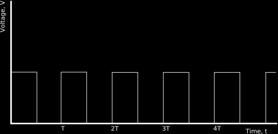
3 Consider examples of current (I) / Voltage (V) time (t) graphs representing d.c. and a.c. d.c. On one side of the time axis a.c. on both side of the time axis Square wave or pulse d.c 3
4 4
5 AC current 5

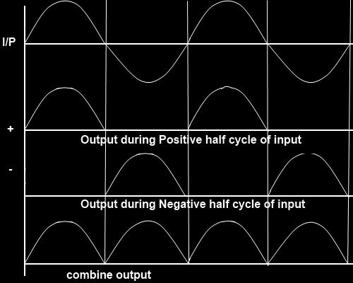
6 Rectified waveforms Once the variation is either completely above or completely below the time axis, it is d.c. Once the variation is both above and below the time axis, it is a.c. Consider sinusoidal a.c. The period T is the time taken to complete one cycle. The frequency, f, is the number of cycles per second. Note: T = 1/f and f = 1/T The peak value or amplitude is the maximum value (of V or I) in either direction. 6
7 Typical effects of an electric current include: 1) Heating effects 2) Magnetic effects 3) Chemical effects Quantities, units, symbols and instruments of measurements. Quantity Typical Symbol q or c Unit & Typical Symbol Coulomb - C Instrument of Measurement 1) Unit Charge 2) Number of N Charge carriers 3) Total Q Coulomb C Quantity of charge 4) Time t Second - s Watch or clock 5) Current I Ampere- A Ammeter (or galvanometer) 6) Voltage or Potential Difference 7) Electromotive force (e.m.f) V Volt - V Voltmeter E or ε Volt- V Voltmeter 8) Resistance R Ohm- Ω Ohmmeter 9) Energy E Joule- J (kwh) Joule meter 10) Work Joule- J Joule meter 11) Power P Watt- W Comments 7
8 Equations 1) Q = nq (where q = e and e = 1.6 x C) 2) Q = IT 3) R = V/I 4) V = IR 5) I = V/R 6) W = QV (where W is work is also electrical energy) 7) P = IV 8) P = I 2 R 9) P = V 2 /R 10) E = Pt 11) E = V 2 t/r 1 kwh = 1000W x 3600s = 3,600,000 J Circuits and Circuit components and their symbols 8
9 Another common component is a potentiometer or potential divider it is an arrangement for tapping off a variable or fixed fraction of a fixed applied voltage. Certain rheostats can be arranged to operate as potential dividers; Potential Difference (p.d.) /Voltage In order for current to flow through a component there must exist a potential difference (i.e. p.d) or voltage across the component. The p.d. / voltage between or across the ends of a conductor or component is the electrical energy per unit charge converted to other forms of energy, i.e. V = E/Q => E = VQ The unit of p.d. is the volt and it is defined as one joule per coulomb. The maximum voltage that can be obtained between the terminals of an electrical power supply, such as a cell, is called the electromotive force (i.e. supply) of the power supply. 9
10 Resistance All components in a circuit offer electrical resistance to the flow of current- some more than others. Certain components offer very low resistances and examples of these are connecting wires, switches, power supplies and ammeters. Other components offer much higher resistances and examples of these are voltmeters and resistors (fixed and variable). The resistance of a component such as a resistor in the form of a wire depends directly on its length and inversely on its area of cross- section. Also, the resistance depends on the nature of the material of which it is made- for instance, materials such as silver, gold, copper and aluminum have low resistances. So the longer the specimen of a given material the greater its resistance and the thinner the specimen, the greater its resistance. The reverse of both of these ideas is also true. The resistance R, of a component can be determined from the equation R = V/I, where v is the p.d./voltage applied across the component and I is the current flowing through the component. The unit of resistance is the ohm (Ω). Resistors in Series and Parallel 10
11 Note the following 1) I = I1 = I2 = I3, i.e. the same current flows through components in series. 2) V = V1 + V2 + V3 i.e. the total individual p.d. across components in series is the sum of the individual p.d.s. 3) R = R1 + R2 + R3, i.e. the total resistance of components in series is the sum of the individual resistances. 4) I = I1 + I2 + I3, i.e. the total current through components in parallel is the sum of the individual currents. 5) V = V1 = V2 = V3, i.e. the total p.d. across components in parallel is the same as that across individual components. 11


12 Ammeters and Voltmeters An ammeter is an instrument for measuring the current through a component and so it must be connected in series with the component. In fact, an ammeter measures and indicates the current flowing through itself and it is assumed that the same current flows through the component since it is in series with the ammeter. 12
13 It is essential that the resistance of the ammeter itself be very small compared with their resistance in the circuit- otherwise inserting it into the circuit will change the very current it is to measure. An ideal ammeter has an extremely low (close to zero) resistance and hence an extremely low (close to zero) p.d. across itself. A voltmeter is an instrument used to measure p.d. (i.e. voltage) across a component and so it is connected in parallel with the component. in fact, a voltmeter measures and indicated the p.d. across itself and it is assumed that this is the same p.d. across the component since it is in parallel with the voltmeter. It is essential that the resistance of the voltmeter be very large compared with any other resistance in the circuit ( especially the resistance of the component across which it is connected) otherwise it will itself alter the very p.d. it is to measure by drawing a significant current away from the component. So an ideal voltmeter has an infinite (i.e. extremely high) resistance and hence draws a negligible (almost zero) current. 13
14 Ohm`s Law This law states that the p.d. applied across a metallic conductor is directly proportional to the current through the conductor, provided that physical conditions such as strain, temperature and illumination, remain constant, so V I and V/I = a constant, i.e. the resistance, R, of the metallic conductor. For a metallic conductor at constant temperature there is a linear relationship between V and I and a graph of V against I, or I against V, (known as the V- I or I- V characteristic), is a straight line through the origin (0,0). Conductors with such V- I or I- V, graphs are known as ohmic conductors. The slope of a V- I graph gives the resistance, R, of the conductor and that of a I- V graph give the reciprocal of the resistance, 1/R, of the conductor. Conductors, which do not have V- I or I- V graphs that are straight lines through the origin are called non- ohmic conductors. Consider typical I- V characteristics for both ohmic and non- ohmic conductors; Ohmic Conductors 1) Metallic conductors (such as pure metals and alloys at constant temperature) 2) An aqueous solution of copper sulphate with copper electrodes 14
15 Non- Ohmic conductors 1) Filament lamp/bulb 2) Carbon resistors 3) Semiconductor Diode 15
 contain three insulated wires- one of these is")
, which is earthed (i.e. grounded) at the house 16")
16 Consider a typical circuit for investigating Ohm`s law and deriving a conductor V- I or I- V characteristic: House Circuits Within the house, the connecting cables (themselves insulated- usually with white plastic) contain three insulated wires- one of these is the live wire, L, (covered with brown plastic insulation), another is the neutral wire, N, (covered with blue plastic insulation), and the third is the earth or ground wire, (covered with green/yellow plastic insulation), which is earthed (i.e. grounded) at the house 16
17 There are three single cables from the pole to the house two live and one neutral. Each live cables carries 110 V (r.m.s) a.c. and by using both 220V (r.m.s) a.c. can also be obtained. Most appliances require 110 V (r.m.s) a.c. and the two live 110 V (r.m.s) a.c. wires share the distribution of energy to these appliances. Certain appliances however, such as some electric stoves, some dryers and air conditioners require 220V (r.ms.) a.c. and for these, thicker connecting wires and special sockets (with matching plugs) must be used. With the house, a ring main circuit exists with the live and neutral wires running in two complete rings around the house. Circuits are tapped off from these rings such that all circuits tapped off are in parallel of each other and with the main supply. So each circuit/appliance operates at the mains voltage. The earth wire is a safety device to prevent an electrical shock to a person in the event of this person touching the metal case or housing of an appliance, which has made contact with a live wire. The earth wire provides a safe alternative path (rather than through the person`s body) for the current to the earth. In addition, the large current (due to the small resistance), which flows in the earth wire, may cause the fuse (in the L wire- E wire circuit) to blow and so break the circuit and turn of the current- thus rendering that circuit safe. A fuse or a circuit breaker is a safety device to minimize a possibility of an overload (i.e. excess) of current flowing through a given 17
18 appliance or circuit- such an occurrence can lead to i) appliance damage ii) electrical fires. A fuse can exist as a metal strip, which melts (i.e. blows ). When a current above a particular value (i.e. the fuse rating) flows through it acts as a circuit breaker, which switches off when a current above a particular value (i.e. the breaker rating) flows through it. The former type generates on the heating effect of a current while the latter type operates on the magnetic effect of a current. The fuse or circuit breaker rating must be greater than the operating current required, but a close as possible to this operating current so that the fuse/circuit breaker will blow (i.e. melt) switch off before overloading can occur. Switches and fuses must always be placed in the live wire Advantages of the parallel connection of domestic appliance include: 1) A malfunction of one appliance does not affect the operation of other appliances. 2) Each appliance can be independently controlled 3) Each appliance can be operated at its rated power 4) All appliances operate at the same voltage- thus appliances can be standardized with respect to operating voltage. 18
19 Adverse effects of an incorrect or fluctuating supply to an appliance include: 1) Current surges which can cause overload and thus lead to i) damage to an appliance ii) electrical fires 2) Current/voltage underload, which can result in an appliance operating below its rated power, or even not operating at all. Ways of reducing waste electrical energy include; 1) Switching off all appliances (e.g. lights) when not in use. 2) Ensuring that all heating /cooling appliances (e.g. electrical stoves /refrigerators) are adequately insulated. 3) Operating appliances (such as air- conditioners) at their lowest possible power rating that will still achieve the objective of using the appliance. 4) Adequately insulating all buildings/rooms that use air conditioners. Electronics the diode A diode is a device with little or no resistance in one direction (i.e. forward bias) and very high resistance in the opposite direction (i.e. reverse bias). 19


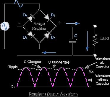
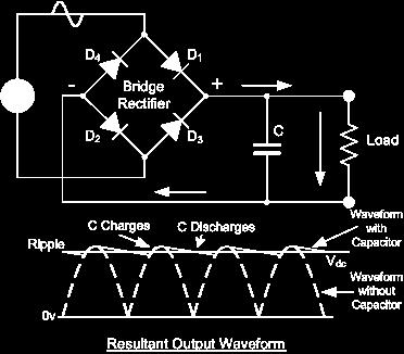
20 A diode conducts in only one direction, i.e. when forward biased it will therefore rectify a.c. i.e. convert a.c. to d.c. the d.c. that results is referred to as half- wave rectified a.c. A typical circuit giving this output is Four diodes connected in a special circuit called a bridge rectifier can produce full wave rectified a.c. 20

21 21
I = q/ t units are C/s = A (ampere)
") Physics I - Notes Ch. 19-20 Current, Resistance, and Electric Circuits Electromotive force (emf = ε = V; units are volts) charge pump ; source that maintains the potential difference (voltage) in a closed
Physics I - Notes Ch. 19-20 Current, Resistance, and Electric Circuits Electromotive force (emf = ε = V; units are volts) charge pump ; source that maintains the potential difference (voltage) in a closed
Downloaded from
 Question 1: What does an electric circuit mean? An electric circuit consists of electric devices, switching devices, source of electricity, etc. that are connected by conducting wires. Question 2: Define
Electric Circuits. Alternate Units. V volt (V) 1 V = 1 J/C V = E P /q V = W/q. Current I ampere (A) 1 A = 1 C/s V = IR I = Δq/Δt
 1 V = 1 J/C V = E P /q V = W/q. Current I ampere (A) 1 A = 1 C/s V = IR I = Δq/Δt") Electric Circuits Quantity Symbol Units Charge Q,q coulomb (C) Alternate Units Formula Electric Potential V volt (V) 1 V = 1 J/C V = E P /q V = W/q Work, energy W, E P joule (J) W = qv E P = qv Current
Electric Circuits Quantity Symbol Units Charge Q,q coulomb (C) Alternate Units Formula Electric Potential V volt (V) 1 V = 1 J/C V = E P /q V = W/q Work, energy W, E P joule (J) W = qv E P = qv Current
YAL. 12 Electricity. Assignments in Science Class X (Term I) IMPORTANT NOTES
 IMPORTANT NOTES") Assignments in Science Class X (Term I) 12 Electricity IMPORTANT NOTES 1. There are two kinds of electric charges i.e., positive and negative. The opposite charges attract each other and the similar charges
Assignments in Science Class X (Term I) 12 Electricity IMPORTANT NOTES 1. There are two kinds of electric charges i.e., positive and negative. The opposite charges attract each other and the similar charges
Syllabus OP49 Test electrical conduction in a variety of materials, and classify each material as a conductor or insulator
 Physics: 14. Current Electricity Please remember to photocopy 4 pages onto one sheet by going A3 A4 and using back to back on the photocopier Syllabus OP49 Test electrical conduction in a variety of materials,
Resistance and Ohm s law
 Resistance and Ohm s law Objectives Characterize materials as conductors or insulators based on their electrical properties. State and apply Ohm s law to calculate current, voltage or resistance in an
Chapter 13. Electric Circuits
 Chapter 13 Electric Circuits Lower Potential Battery (EMF - E) - + Higher Potential Bulb (Resistor) Wires (No Change in Potential) EMF (Voltage Source) _ + Resistor Working Circuits For a circuit to work,
ELECTRIC Circuits Test
 ELECTRIC Circuits Test Name: /50 Multiple Choice (1 mark each) ( 13 marks) 1. Circle the best answer for each of the multiple choice questions below: Quantity measured Units used 1 -- potential difference
CURRENT ELECTRICITY. 1. The S.I. unit of power is (a) Henry (b) coulomb (c) watt (d) watt-hour Ans: c
 Henry (b) coulomb (c) watt (d) watt-hour Ans: c") CURRENT ELECTRICITY 1. The S.I. unit of power is (a) Henry (b) coulomb (c) watt (d) watt-hour 2. Electric pressure is also called (a) resistance (b) power (c) voltage (d) energy 3. The substances which
CURRENT ELECTRICITY 1. The S.I. unit of power is (a) Henry (b) coulomb (c) watt (d) watt-hour 2. Electric pressure is also called (a) resistance (b) power (c) voltage (d) energy 3. The substances which
A piece of wire of resistance R is cut into five equal parts. These parts are then connected in
 Page 221»Exercise» Question 1: A piece of wire of resistance R is cut into five equal parts. These parts are then connected in parallel. If the equivalent resistance of this combination is R', then the
TO INVESTIGATE THE VARIATION OF CURRENT (I) WITH P.D. (V) FOR (a) A METALLIC CONDUCTOR
 WITH P.D. (V) FOR (a) A METALLIC CONDUCTOR") FOR (a) A METALLIC CONDUCTOR Low voltage power supply, rheostat, voltmeter, ammeter, length of nichrome wire. 6 A - Nichrome wire 1. Set up the circuit as shown and set the voltage supply at 6 d.c. 2.
FOR (a) A METALLIC CONDUCTOR Low voltage power supply, rheostat, voltmeter, ammeter, length of nichrome wire. 6 A - Nichrome wire 1. Set up the circuit as shown and set the voltage supply at 6 d.c. 2.
An electric circuit consists of electric devices, switching devices, source of electricity, etc. that are
 Class:X Page 200»Question» What does an electric circuit mean? An electric circuit consists of electric devices, switching devices, source of electricity, etc. that are connected by conducting wires. Define
(a) In the circuit below, lamps P and Q are identical. The reading on the ammeter is 3A. The cell shown is of emf. 6V. A P [2] ...
![(a) In the circuit below, lamps P and Q are identical. The reading on the ammeter is 3A. The cell shown is of emf. 6V. A P [2] ...](/thumbs/87/96678051.jpg "(a) In the circuit below, lamps P and Q are identical. The reading on the ammeter is 3A. The cell shown is of emf. 6V. A P [2] ...") High Demand Questions QUESTIONSHEET 1 (a) In the circuit below, lamps P and Q are identical. The reading on the ammeter is 3A. The cell shown is of emf. 6V. A P Q Calculate the current that passes through
High Demand Questions QUESTIONSHEET 1 (a) In the circuit below, lamps P and Q are identical. The reading on the ammeter is 3A. The cell shown is of emf. 6V. A P Q Calculate the current that passes through
Chapter 2: Electricity
 Chapter 2: Electricity Lesson 2.1 Static Electricity 1 e.g. a polythene rod Lesson 2.3 Electric current 1 I = Q / t = 80 / 16 = 5 A 2 t = Q / I = 96 / 6 = 16 s 1b e.g. a metal wire 2 If static charge begins
Resistance and Ohm s Law R V I. 1 ohm = 1 volt ampere
 Resistance and Ohm s Law If you maintain an electric potential difference, or voltage V, across any conductor, an electric current occurs. In general, the magnitude of the current depends on the potential
CBSE TEST PAPER-01 CLASS - X Science (Electricity and its Effects)
") CBSE TEST PAPER-01 CLASS - X Science (Electricity and its Effects) 1. Which two circuit components are connected in parallel in the following circuit diagram? - >. < < 2. A metallic conductor has loosely
CBSE TEST PAPER-01 CLASS - X Science (Electricity and its Effects) 1. Which two circuit components are connected in parallel in the following circuit diagram? - >. < < 2. A metallic conductor has loosely
Chapter 21 Electric Current and Direct-Current Circuit
 Chapter 21 Electric Current and Direct-Current Circuit Outline 21-1 Electric Current 21-2 Resistance and Ohm s Law 21-3 Energy and Power in Electric Circuit 21-4 Resistance in Series and Parallel 21-5
South Pasadena A.P. Physics Chapter Electric Current & DC Circuits Date / / Period Electricity Practice Test
 South Pasadena A.P. Physics Name Chapter 18-19 Electric Current & DC Circuits Date / / Period 1 2 3 4 Electricity Practice Test Electric Current I = Q/t 1. A charge of 30 Coulombs passes through a 24-ohm
Unit 4: Electricity (Part 1)
") Unit 4: Electricity (Part 1) Learning Outcomes Students should be able to: 1. Explain what is meant by current, potential difference and resistance, stating their units 2. Draw and interpret circuit diagrams
Unit 4: Electricity (Part 1) Learning Outcomes Students should be able to: 1. Explain what is meant by current, potential difference and resistance, stating their units 2. Draw and interpret circuit diagrams
GCSE Physics. The PiXL Club Ltd, Company number
 he PiXL Club The PiXL Club The PiXL Club The PiXL Club The PiXL Club The PiXL Club The PiXL Club The PiXL Club The PiXL Club The PiXL Club The PiXL Club The PiXL Club The PiXL Club The PiXL Club he PiXL
νµθωερτψυιοπασδφγηϕκλζξχϖβνµθωερτ ψυιοπασδφγηϕκλζξχϖβνµθωερτψυιοπα σδφγηϕκλζξχϖβνµθωερτψυιοπασδφγηϕκ χϖβνµθωερτψυιοπασδφγηϕκλζξχϖβνµθ
 θωερτψυιοπασδφγηϕκλζξχϖβνµθωερτψ υιοπασδφγηϕκλζξχϖβνµθωερτψυιοπασδ φγηϕκλζξχϖβνµθωερτψυιοπασδφγηϕκλζ ξχϖβνµθωερτψυιοπασδφγηϕκλζξχϖβνµ θωερτψυιοπασδφγηϕκλζξχϖβνµθωερτψ Nature of Sound υιοπασδφγηϕκτψυιοπασδφγηϕκλζξχϖβν
Electrical Measurements
 Electrical Measurements INTRODUCTION In this section, electrical measurements will be discussed. This will be done by using simple experiments that introduce a DC power supply, a multimeter, and a simplified
Chapter 20 Electric Circuits
 Chapter 20 Electric Circuits 1 20.1 Electromotive Force and Current In an electric circuit, an energy source and an energy consuming device are connected by conducting wires through which electric charges
Module 1, Lesson 2 Introduction to electricity. Student. 45 minutes
 Module 1, Lesson 2 Introduction to electricity 45 minutes Student Purpose of this lesson Explanations of fundamental quantities of electrical circuits, including voltage, current and resistance. Use a
Electricity. Intext Exercise 1
 Intext Exercise 1 Question 1: What does an electric circuit mean? Solution 1: A continuous and closed path of an electric current is called an electric circuit. electric circuit consists of electric devices
ExamLearn.ie. Electricity in the Home & Electronics
 ExamLearn.ie Electricity in the Home & Electronics Electricity in the Home & Electronics Mains supply and safety The mains supply to the sockets in your house or school is at 230 V a.c. This voltage could
The following symbols are used in electric circuits:
 Circuit Electricity The following symbols are used in electric circuits: Four devices are commonly used in the laboratory to study Ohm s law: the battery, the voltmeter, the ammeter and a resistance. The
6-2 Electricity Trilogy
 6-2 Electricity Trilogy.0 Most domestic appliances are connected to the mains electricity.. What is the frequency of mains electricity? Tick one box [ mark].05 A 50 Hz 230 V.2 What is the potential difference
SECTION 3 BASIC AUTOMATIC CONTROLS UNIT 12 BASIC ELECTRICITY AND MAGNETISM. Unit Objectives. Unit Objectives 2/29/2012
 SECTION 3 BASIC AUTOMATIC CONTROLS UNIT 12 BASIC ELECTRICITY AND MAGNETISM Unit Objectives Describe the structure of an atom. Identify atoms with a positive charge and atoms with a negative charge. Explain
PHYS 1402 General Physics II Experiment 5: Ohm s Law
 PHYS 1402 General Physics II Experiment 5: Ohm s Law Student Name Objective: To investigate the relationship between current and resistance for ordinary conductors known as ohmic conductors. Theory: For
ANSWERS AND MARK SCHEMES. (a) 3 A / 2 1 = 1.5 A 1. (b) 6 V 1. (c) resistance = V / I 1 = 6 / (b) I = V / R 1 = 3 / 15 1 = 0.
 3 A / 2 1 = 1.5 A 1. (b) 6 V 1. (c) resistance = V / I 1 = 6 / (b) I = V / R 1 = 3 / 15 1 = 0.") QUESTIONSHEET (a) 3 A / 2 =.5 A (b) 6 V (c) resistance = V / I = 6 /.5 = 4 Ω QUESTIONSHEET 2 TOTAL / 6 (a) 5 Ω + 0 Ω = 5 Ω (b) I = V / R = 3 / 5 = 0.2 A Units are essential in calculations. Sometimes eamination
QUESTIONSHEET (a) 3 A / 2 =.5 A (b) 6 V (c) resistance = V / I = 6 /.5 = 4 Ω QUESTIONSHEET 2 TOTAL / 6 (a) 5 Ω + 0 Ω = 5 Ω (b) I = V / R = 3 / 5 = 0.2 A Units are essential in calculations. Sometimes eamination
Chapter 12 Electric Circuits
 Conceptual Physics/ PEP Name: Date: Chapter 12 Electric Circuits Section Review 12.1 1. List one way electric current is similar to water current and one way it is different. 2. Draw a circuit diagram
 Question 3.1: The storage battery of a car has an emf of 12 V. If the internal resistance of the battery is 0.4Ω, what is the maximum current that can be drawn from the battery? Emf of the battery, E =
A battery transforms chemical energy into electrical energy. Chemical reactions within the cell create a potential difference between the terminals
 D.C Electricity Volta discovered that electricity could be created if dissimilar metals were connected by a conductive solution called an electrolyte. This is a simple electric cell. The Electric Battery
a) b) c) d) 0.01.
 b) c) d) 0.01.") 1. A galvanometer is an electromechanical device, it concerts: a) Mechanical energy into electrical energy. b) Electrical energy into mechanical energy. c) Elastic energy into electrical energy. d) Electromagnetic
1. A galvanometer is an electromechanical device, it concerts: a) Mechanical energy into electrical energy. b) Electrical energy into mechanical energy. c) Elastic energy into electrical energy. d) Electromagnetic
Circuits. What is Ohm s law? Section 1: Ohm s Law. Suggested Film. Extension Questions. Q1. What is current? Q2. What is voltage?
 Circuits PHYSICS ELECTRICITY AND CIRCUITS CIRCUITS Section 1: Ohm s Law What is Ohm s law? Ohm s law gives the relation between current, resistance and voltage. It states that the current which fl ows
Q2. Figure 1 shows the oscilloscope trace an alternating current (a.c.) electricity supply produces.
 electricity supply produces.") SERIES AND PARALEL CIRCUITS Q1. A student set up the electrical circuit shown in the figure below. (a) The ammeter displays a reading of 0.10 A. Calculate the potential difference across the 45 Ω resistor.
SERIES AND PARALEL CIRCUITS Q1. A student set up the electrical circuit shown in the figure below. (a) The ammeter displays a reading of 0.10 A. Calculate the potential difference across the 45 Ω resistor.
Section A. Two resistors of 10 Ω and 15 Ω are connected in series to a battery of 6V. How can the values of current passing through them be compared?
 EXAM PRACTICE Past Year Board Questions CBSE-Class X Physics Electricity Section A (1 mark each) Question 1. Question 2. Question 3. Question 4. Question 5. Question 6. How is an ammeter connected in a
E 1 Ι 1 R 1 R 2 Ι 3 R 3 E 2 Ι 2
 1 (a) A student has been asked to make an electric heater. The heater is to be rated as 12 V 60 W, and is to be constructed of wire of diameter 0.54 mm. The material of the wire has resistivity 4.9 x 10
1. A battery of internal resistance 2 Ω is connected to an external resistance of 10 Ω. The current is 0.5 A.
 . A battery of internal resistance 2 Ω is connected to an external resistance of 0 Ω. The current is 0.5 What is the emf of the battery?.0 V B. 5.0 V C. 6.0 V D. 24.0 V 2. Two electrodes, separated by
A battery transforms chemical energy into electrical energy. Chemical reactions within the cell create a potential difference between the terminals
 D.C Electricity Volta discovered that electricity could be created if dissimilar metals were connected by a conductive solution called an electrolyte. This is a simple electric cell. The Electric Battery
A battery of emf 10 V and internal resistance 3 Ω is connected to a resistor. If the current
 Question 3.1: The storage battery of a car has an emf of 12 V. If the internal resistance of the battery is 0.4Ω, what is the maximum current that can be drawn from the battery? Emf of the battery, E =
Current Electricity. What is Current Electricity? Electrical Circuits Electrochemical Cells. Wet, Dry and Fuel Cells
 Current Electricity What is Current Electricity? Electrical Circuits Electrochemical Cells Wet, Dry and Fuel Cells Current Electricity Current Electricity continuous flow of electrons in a closed circuit
PHYSICS FORM 5 ELECTRICITY
 Current Types of Current: 1. Conventional Current 2. Electric Current Conventional Current Long ago, it was believed that current was a flow of positive charges. The direction of conventional current therefore
νµθωερτψυιοπασδφγηϕκλζξχϖβνµθωερτ ψυιοπασδφγηϕκλζξχϖβνµθωερτψυιοπα σδφγηϕκλζξχϖβνµθωερτψυιοπασδφγηϕκ χϖβνµθωερτψυιοπασδφγηϕκλζξχϖβνµθ
 θωερτψυιοπασδφγηϕκλζξχϖβνµθωερτψ υιοπασδφγηϕκλζξχϖβνµθωερτψυιοπασδ φγηϕκλζξχϖβνµθωερτψυιοπασδφγηϕκλζ ξχϖβνµθωερτψυιοπασδφγηϕκλζξχϖβνµ EE 331 Design Project Final Report θωερτψυιοπασδφγηϕκλζξχϖβνµθωερτψ
Wallace Hall Academy Physics Department. Electricity. Pupil Notes Name:
 Wallace Hall Academy Physics Department Electricity Pupil Notes Name: 1 Learning intentions for this unit? Be able to state that there are two types of charge; positive and negative Be able to state that
Regents Physics Mr. Mellon Based on Chapter 22 and 23
 Name Regents Physics Mr. Mellon Based on Chapter 22 and 23 Essential Questions What is current? How is it measured? What are the relationships for Ohm s Law? What device measures current and how is it
Name: Period: Date: 2. In the circuit below, n charge carriers pass the point P in a time t. Each charge carrier has charge q.
 Name: Period: Date: IB-1 Practice Electrical Currents, Resistance, and Circuits Multiple Choice Questions 1. In the circuit below, which meter is not correctly connected? A 1 3 A 2 4 A. 1 B. 2 C. 3 D.
1. A battery of internal resistance 2 Ω is connected to an external resistance of 10 Ω. The current is 0.5 A. D. 24.
 1. A battery of internal resistance 2 Ω is connected to an external resistance of 10 Ω. The current is 0.5 A. What is the emf of the battery? A. 1.0 V B. 5.0 V C. 6.0 V D. 24.0 V (Total 1 mark) IB Questionbank
Lecture 3.10 ELECTRICITY Alternating current Electrical safety
 Lecture 3.1 ELECTRCTY Alternating current Electrical safety Alternating Current (ac) Batteries are a source of steady or direct voltage. Current in a circuit powered by a battery is also steady and is
Section B: Electricity
 Section B: Electricity The best way to remember the information in this chapter is to get a pen and paper and write down your answers Electricity - Current - Voltage - Power 1 What is Electricity? 2 What
Resistance and Ohm s Law
 Resistance and Ohm s Law Textbook pages 290 301 Section 8.3 Summary Before You Read Do you think electrons can move through all conducting substances equally well? Give your reasons why or why not on the
State an equation giving the total power delivered by the battery.
 Electricity Paper2 (set 1) 1. This question is about electric circuits. (a) Define (i) electromotive force (emf ) of a battery. (1) (ii) electrical resistance of a conductor. (1) (b) A battery of emf ε
CURRENT, POTENTIAL DIFFERENCE AND RESISTANCE PART I
 CURRENT, POTENTIAL DIFFERENCE AND RESISTANCE PART I Q1. An electrical circuit is shown in the figure below. (a) The current in the circuit is direct current. What is meant by direct current? Tick one box.
Unit 15: Electrical Circuits and their Applications
 Unit 15: Electrical Circuits and their Applications Level: 3 Unit type: Internal Guided learning hours: 60 Unit in brief This unit covers the principles of electricity, including measurements of electrical
... (1) A battery of emf ε and negligible internal resistance is connected in series to two resistors. The current in the circuit is I.
 A battery of emf ε and negligible internal resistance is connected in series to two resistors. The current in the circuit is I.") 1. This question is about electric circuits. (a) Define (i) electromotive force (emf ) of a battery. (ii) electrical resistance of a conductor. (b) A battery of emf ε and negligible internal resistance
1. This question is about electric circuits. (a) Define (i) electromotive force (emf ) of a battery. (ii) electrical resistance of a conductor. (b) A battery of emf ε and negligible internal resistance
Duration of resource: 23 Minutes. Year of Production: Stock code: VEA12041
 ADDITIONAL RESOURCES We use electrical circuits every day. In the home, the car, at work and school they are a vital part of our lives. This program covers the basics of electrical circuits in detail.
These are samples of learning materials and may not necessarily be exactly the same as those in the actual course. Contents 1.
 Contents These are samples of learning materials and may not necessarily be exactly the same as those in the actual course. Contents 1 Introduction 2 Ohm s law relationships 3 The Ohm s law equation 4
Electromagnetism Unit- Current Sub-Unit
 4.2.1 Electrical Current Definitions current unit: or requires: Example #3 A wire carries a current of 50 amperes. How much charge flows through the wire in 10 seconds? How many electrons pass through
ELECTRIC CIRCUITS PREVIEW QUICK REFERENCE. Important Terms
 ELECTRC CRCUTS PREEW Conventional current is the flow of positive charges though a closed circuit. The current through a resistance and the voltage which produces it are related by Ohm s law. Power is
The equation which links current, potential difference and resistance is:
 Q1.An electrical circuit is shown in the figure below. (a) The current in the circuit is direct current. What is meant by direct current? Tick one box. Current that continuously changes direction. Current
Wallace Hall Academy. CfE Higher Physics. Unit 3 - Electricity Notes Name
 Wallace Hall Academy CfE Higher Physics Unit 3 - Electricity Notes Name 1 Electrons and Energy Alternating current and direct current Alternating current electrons flow back and forth several times per
D V (Total 1 mark)
") 1. One electronvolt is equal to A. 1.6 10 19 C. B. 1.6 10 19 J. C. 1.6 10 19 V. D. 1.6 10 19 W. 2. A battery of internal resistance 2 Ω is connected to an external resistance of 10 Ω. The current is 0.5
1. One electronvolt is equal to A. 1.6 10 19 C. B. 1.6 10 19 J. C. 1.6 10 19 V. D. 1.6 10 19 W. 2. A battery of internal resistance 2 Ω is connected to an external resistance of 10 Ω. The current is 0.5
1 Ω = 1 V A -1 ELECTRICAL RESISTANCE (R) 1. Candidates should be able to:
 1. Candidates should be able to:") ELECTRCAL RESSTANCE (R) 1 Candidates should be able to: Define RESSTANCE. Of a conductor or component is a measure of its opposition to the flow of charge (i.e. to electric current). Select and use the
ELECTRCAL RESSTANCE (R) 1 Candidates should be able to: Define RESSTANCE. Of a conductor or component is a measure of its opposition to the flow of charge (i.e. to electric current). Select and use the
8866 H1 Physics J2/ D.C. Circuits
 7. D.C. CIRCUITS Content Practical circuits Series and parallel arrangements Learning Outcomes Candidates should be able to: (a) (b) (c) (d) (e) recall and use appropriate circuit symbols as set out in
Introduction to Engineering ENGR Electrical Engineering. Dr. Coates
 Introduction to Engineering ENG 1100 - Electrical Engineering Dr. Coates Branches of Electrical Engineering Circuits/Microelectronics Communications Computer Hardware and Software, Digital Logic, Microprocessor
Figure 1. (b) (i) State what happens to the resistance of the filament lamp as the current increases.
 (i) State what happens to the resistance of the filament lamp as the current increases.") Q1.(a) Sketch, on Figure 1, the current voltage (IV) characteristic for a filament lamp for currents up to its working power. Figure 1 (b) (i) State what happens to the resistance of the filament lamp
Q1.(a) Sketch, on Figure 1, the current voltage (IV) characteristic for a filament lamp for currents up to its working power. Figure 1 (b) (i) State what happens to the resistance of the filament lamp
Exercise MM About the Multimeter
 Exercise MM About the Multimeter Introduction Our world is filled with devices that contain electrical circuits in which various voltage sources cause currents to flow. Electrical currents generate heat,
charge time Electric Current and Circuits Current HEAT will flow if there is a difference in temperature
 Electric Current and Circuits Electrons will flow if there is a difference in electric pressure. Electric pressure is called Potential, and is measured in Volts. If there is no difference in pressure from
Conceptual Physics. Chapter 23: ELECTRIC CURRENT
 Conceptual Physics Chapter 23: ELECTRIC CURRENT Electric Potential Unit of measurement: volt, 1 volt 1 joule 1 coulomb Example: Twice the charge in same location has twice the electric potential energy
Ohm's Law and the Measurement of Resistance
 Ohm's Law and the Measurement of Resistance I. INTRODUCTION An electric current flows through a conductor when a potential difference is placed across its ends. The potential difference is generally in
Calculate the maximum amount of energy this battery can deliver.
 1 A battery in a laptop computer has an electromotive force (emf) of 14.8 V and can store a maximum charge of 15. 5 10 3 C. The battery has negligible internal resistance. Calculate the maximum amount
Chapter 20. Circuits. q I = t. (a) (b) (c) Energy Charge
 (b) (c) Energy Charge") Chapter 0 n an electric circuit, an energy source and an energy consuming device are connected by conducting wires through which electric charges move. Circuits Within a battery, a chemical reaction occurs
Chapter 0 n an electric circuit, an energy source and an energy consuming device are connected by conducting wires through which electric charges move. Circuits Within a battery, a chemical reaction occurs
Figure 1. (a) The wire in an unused probe has a resistance of Ω and a length of 0.50 m. Calculate the diameter of the wire.
 The wire in an unused probe has a resistance of Ω and a length of 0.50 m. Calculate the diameter of the wire.") A wire probe is used to measure the rate of corrosion in a pipe carrying a corrosive liquid. The probe is made from the same metal as the pipe. Figure shows the probe. The rate of corrosion of the wire
A wire probe is used to measure the rate of corrosion in a pipe carrying a corrosive liquid. The probe is made from the same metal as the pipe. Figure shows the probe. The rate of corrosion of the wire
ELECTRIC CURRENT VERY SHORT ANSWER QUESTIONS
 ELECTRIC CURRENT VERY SHORT ANSWER QUESTIONS 1. Give the equivalent of V A -1. 2. Ten identical wires, each having a resistance of one ohm, are joined in parallel. What is the equivalent resistance of
PHYSICS EXPERIMENTS (ELECTRICITY)
") PHYSICS EXPERIMENTS (ELECTRICITY) In the matter of physics, the first lessons should contain nothing but what is experimental and interesting to see. A pretty experiment is in itself often more valuable
PHYSICS EXPERIMENTS (ELECTRICITY) In the matter of physics, the first lessons should contain nothing but what is experimental and interesting to see. A pretty experiment is in itself often more valuable
ExamLearn.ie. Current Electricity
 ExamLearn.ie Current Electricity Current Electricity An electric current is a flow of electric charge. If a battery is connected to each end of a conductor, the positive terminal will attract the free
Experiment 3. Ohm s Law. Become familiar with the use of a digital voltmeter and a digital ammeter to measure DC voltage and current.
 Experiment 3 Ohm s Law 3.1 Objectives Become familiar with the use of a digital voltmeter and a digital ammeter to measure DC voltage and current. Construct a circuit using resistors, wires and a breadboard
Fig [5]
![Fig [5]](/thumbs/82/85456687.jpg "Fig [5]") 1 (a) Fig. 4.1 shows the I-V characteristic of a light-emitting diode (LED). 40 I / 10 3 A 30 20 10 0 1.0 1.5 2.0 V / V Fig. 4.1 (i) In Describe the significant features of the graph in terms of current,
1 (a) Fig. 4.1 shows the I-V characteristic of a light-emitting diode (LED). 40 I / 10 3 A 30 20 10 0 1.0 1.5 2.0 V / V Fig. 4.1 (i) In Describe the significant features of the graph in terms of current,
Experiment 2. Ohm s Law. Become familiar with the use of a digital voltmeter and a digital ammeter to measure DC voltage and current.
 Experiment 2 Ohm s Law 2.1 Objectives Become familiar with the use of a digital voltmeter and a digital ammeter to measure DC voltage and current. Construct a circuit using resistors, wires and a breadboard
Electricity. AQA Physics topic 2
 Electricity AQA Physics topic 2 Identify circuit components from their symbols. Draw and interpret simple circuit diagrams. Construct a simple electrical circuit. State that resistance restricts the size
Current, resistance, and Ohm s law
 Current, resistance, and Ohm s law Apparatus DC voltage source set of alligator clips 2 pairs of red and black banana clips 3 round bulb 2 bulb sockets 2 battery holders or 1 two-battery holder 2 1.5V
Ohm s Law and Electrical Circuits
 Ohm s Law and Electrical Circuits INTRODUCTION In this experiment, you will measure the current-voltage characteristics of a resistor and check to see if the resistor satisfies Ohm s law. In the process
DC Circuits. Date: Introduction
 Group # Date: Names: DC Circuits Introduction In this experiment you will examine how to make simple DC measurements that involve current, voltage, and resistance. The current I through a resistor R with
Science 9 Electricity Objectives Greene s Study Guide
 Electricity Objective By the end of this unit, students are expected to be able to #1. explain the production of static electrical charges in some common - recognize that electricity is an integral part
Voltage (V) Electrical Potential. Current and Circuits. Dry Cell Voltage Source. Voltage Sources
 Electrical Potential. Current and Circuits. Dry Cell Voltage Source. Voltage Sources") Current and Circuits Current flows from a higher potential to a lower potential (We need a voltage) circuit is a continuous loop of flowing charge. t must be a closed loop in order to work voltage source
Current and Circuits Current flows from a higher potential to a lower potential (We need a voltage) circuit is a continuous loop of flowing charge. t must be a closed loop in order to work voltage source
Technician License Course Chapter 3. Lesson Plan Module 4 Electricity
 Technician License Course Chapter 3 Lesson Plan Module 4 Electricity Fundamentals of Electricity Radios are powered by electricity and radio signals are a form of electrical energy. A basic understanding
VISUAL PHYSICS ONLINE. Experiment PA41A ELECTRIC CIRCUITS
 VISUAL PHYSICS ONLINE Experiment PA41A ELECTRIC CIRCUITS Equipment (see Appendices) 12V DC power supply (battery): multimeter (and/or milliammeter and voltmeter); electrical leads; alligator clips; fixed
DC Circuits and Ohm s Law
 DC Circuits and Ohm s Law INTRODUCTION During the nineteenth century so many advances were made in understanding the electrical nature of matter that it has been called the age of electricity. One such
Basic Circuits. PC1222 Fundamentals of Physics II. 1 Objectives. 2 Equipment List. 3 Theory
 PC1222 Fundamentals of Physics II Basic Circuits 1 Objectives Investigate the relationship among three variables (resistance, current and voltage) in direct current circuits. Investigate the behaviours
Voltage, Current, and Resistance. Objectives
 Voltage, Current, and Resistance ELEC 111 Objectives Define voltage and discuss its characteristics Define current and discuss its characteristics Define resistance and discuss its characteristics 21 January
ELECTRIC CIRCUITS. 1. Which one of the following situations results in a conventional electric current that flows westward?
 chapter ELECTRIC CIRCUITS www.tutor-homework.com (for tutoring, homework help, or help with online classes) Section 20.1 Electromotive Force and Current Section 20.2 Ohm s Law 1. Which one of the following
MEASUREMENTS & INSTRUMENTATION ANALOG AND DIGITAL METERS
 MEASUREMENTS & INSTRUMENTATION ANALOG AND DIGITAL METERS ANALOG Metering devices Provides monotonous (continuous) movement. ELECTRICAL MEASURING INSTRUMENTS ANALOG METERS A d Arsonval galvanometer (Moving
PhysicsAndMathsTutor.com 1
 Q1. (a) A metal wire of length 1.4 m has a uniform cross-sectional area = 7.8 10 7 m 2. Calculate the resistance, R, of the wire. resistivity of the metal = 1.7 10 8 Ωm............ (b) The wire is now
rheostat (about 100 ) multimeter
 multimeter") 0BOhm's Law and Resistivity (approx. 2 h) (8/6/15) 1BIntroduction In this lab you will investigate simple DC (direct or constant current) circuits using a DC power supply, a multimeter and wire resistors.
0BOhm's Law and Resistivity (approx. 2 h) (8/6/15) 1BIntroduction In this lab you will investigate simple DC (direct or constant current) circuits using a DC power supply, a multimeter and wire resistors.
DC CIRCUITS AND OHM'S LAW
 July 15, 2008 DC Circuits and Ohm s Law 1 Name Date Partners DC CIRCUITS AND OHM'S LAW AMPS - VOLTS OBJECTIVES OVERVIEW To learn to apply the concept of potential difference (voltage) to explain the action
UNIVERSITY OF TECHNOLOGY, JAMAICA SCHOOL OF ENGENEERING. Electrical Engineering Science. Laboratory Manual
 UNIVERSITY OF TECHNOLOGY, JAMAICA SCHOOL OF ENGENEERING Electrical Engineering Science Laboratory Manual Table of Contents Experiment #1 OHM S LAW... 3 Experiment # 2 SERIES AND PARALLEL CIRCUITS... 8
Lesson 2: How Radio Works
 Lesson 2: How Radio Works Preparation for Amateur Radio Technician Class Exam Topics How radios work Current Frequency & Wavelength Radio Frequencies Quick review of Metric Electricity Conductors & Insulators
Electrical Components and their Functions
 Electrical Components and their Functions Electricity & Electronics All electrical appliances and electronic devices depend on electrical circuits. The main difference between electricity & electronics
CHAPTER 5 Test B Lsn 5-6 to 5-8 TEST REVIEW
 IB PHYSICS Name: Period: Date: DEVIL PHYSICS BADDEST CLASS ON CAMPUS CHAPTER 5 Test B Lsn 5-6 to 5-8 TEST REVIEW 1. This question is about electric circuits. (a) (b) Define (i) (ii) electromotive force