Transformers. Dr. Gamal Sowilam
|
|
|
- Rodney Bates
- 5 years ago
- Views:
Transcription
1 Transformers Dr. Gamal Sowilam
2 OBJECTIVES Become familiar with the flux linkages that exist between the coils of a transformer and how the voltages across the primary and secondary are established. Understand the operation of an iron-core and air-core transformer and how to calculate the currents and voltages of the primary and secondary circuits. Be aware of how the transformer is used for impedance matching purposes to ensure a high level of power transfer. Become aware of all the components that make up the equivalent circuit of a transformer and how they affect its performance and frequency response. Understand how to use and interpret the dot convention of mutually coupled coils in a network.
3 INTRODUCTION Mutual inductance is a phenomenon basic to the operation of the transformer, an electrical device used today in almost every field of electrical engineering. This device plays an integral part in power distribution systems and can be found in many electronic circuits and measuring instruments. In this chapter, we discuss three of the basic applications of a transformer: to build up or step down the voltage or current, to act as an impedance matching device, and to isolate (no physical connection) one portion of a circuit from another.

4 FARADAY S LAW OF ELECTROMAGNETIC INDUCTION Generating an induced voltage by moving a conductor through a magnetic field. If a coil of N turns is placed in the region of a changing flux, as in Fig. 12.2, a voltage will be induced across the coil as determined by Faradays law:

5 LENZ S LAW If the current increases in magnitude, the flux linking the coil also increase. However, that a changing flux linking a coil induces a voltage across the coil. For this coil, therefore, an induced voltage is developed across the coil due to the change in current through the coil. The polarity of this induced voltage tends to establish a current in the coil that produces a flux that will oppose any change in the original flux. In other words, the induced effect ( eind) is a result of the increasing current through the coil. Lenz law state that: an induced effect is always such as to oppose the cause that produced it.
 Inductors are coils of various dimensions designed to introduce specified amounts of inductance into a circuit.")
6 SELF-INDUCTANCE The ability of a coil to oppose any change in current is a measure of the self-inductance L of the coil. Inductance is measured in henries (H) Inductors are coils of various dimensions designed to introduce specified amounts of inductance into a circuit. The inductance of a coil varies directly with the magnetic properties of the coil. Ferromagnetic materials, therefore, are frequently employed to increase the inductance by increasing the flux linking the coil.
7 A coil wound on a magnetic core, such as that shown in Figure is frequently used in electric circuits. This coil may be represented by an ideal circuit element, called inductance, which is defined as the flux linkage of the coil per ampere of its current. Coil-core assembly. Equivalent inductance.
8 MUTUAL INDUCTANCE the coil to which the source is applied is called the primary, and the coil to which the load is applied is called the secondary. Defining the components of a transformer. The Primary voltage The secondary voltage induced is Since the maximum level of m is p, the coefficient of coupling between two coils can never be greater than 1.


9 MUTUAL INDUCTANCE Windings having different coefficients of coupling.
10 it will never approach a level of 1. Those coils with low coefficients of coupling are said to be loosely coupled. For the secondary, we have The mutual inductance between the two coils is determined by or mutual inductance between two coils is proportional to the instantaneous change in flux linking one coil due to an instantaneous change in current through the other coil. In terms of the inductance of each coil and the coefficient of coupling, the mutual inductance is determined by

11 The secondary voltage es can also be found in terms of the mutual inductance if we rewrite this equation as: Similarly,
12 EXAMPLE 1 a. Find the mutual inductance M. b. Find the induced voltage ep if the flux p changes at the rate of 450 mwb/s. c. Find the induced voltage es for the same rate of change indicated in part (b). d. Find the induced voltages ep and es if the current ip changes at the rate of 0.2 A/ms.
13 Solutions:

14 THE IRON-CORE TRANSFORMER The coefficient of coupling is its maximum value,1, Ideal Transformer neglect losses, leakage reactance, the hysteresis and eddy current losses

15 In fact, the magnitude of the flux is directly proportional to the current through the primary windings. Therefore, the two are in phase, and for sinusoidal inputs, the magnitude of the flux will vary as a sinusoid also. That is, if The induced voltage across the primary due to a sinusoidal input can be determined by Faradays law: The effective value of ep is
16 For the case under discussion, where the flux linking the secondary equals that of the primary, if we repeat the procedure just described for the induced voltage across the secondary, we get:
17 If we consider that and divide one by the other, that is, The instantaneous values of ep and es are therefore related by a constant determined by the turns ratio. Since their instantaneous magnitudes are related by a constant, the induced voltages are in phase, and the above Equation can be changed to include phasor notation
18 The ratio Np/Ns, usually represented by the lowercase letter a, is referred to as the transformation ratio: If a 1, the transformer is called a step-up transformer since the voltage Es Ep; that is,

19 EXAMPL 2 For the iron-core transformer of Figure a. Find the maximum flux m. b. Find the secondary turns Ns.
20 Solutions:
21 REFLECTED IMPEDANCE AND POWER In the previous section we found that Dividing the first by the second, we have
22 However, since That is, the impedance of the primary circuit of an ideal transformer is the transformation ratio squared times the impedance of the load. Note that if the load is capacitive or inductive, the reflected impedance is also capacitive or inductive. For the ideal iron-core transformer,

23 EXAMPLE 3 For the iron-core transformer of Figure: a. Find the magnitude of the current in the primary and the impressed voltage across the primary. b. Find the input resistance of the transformer.
24 Solutions:
25 EXAMPLE 4 For the residential supply appearing in Figure, determine (assuming a totally resistive load) the following: a. the value of R to ensure a balanced load b. the magnitude of I1 and I2 c. the line voltage VL d. the total power delivered for a balanced three-phase load e. the turns ratio a= Np/Ns
26
27
28 IMPEDANCE MATCHING, ISOLATION, AND DISPLACEMENT Transformers can be particularly useful when you are trying to ensure that a load receives maximum power from a source. Recall that maximum power is transferred to a load when its impedance is a match with the internal resistance of the supply. Even if a perfect match is unattainable, the closer the load matches the internal resistance, the greater is the power to the load and the more efficient is the system. Unfortunately, unless it is planned as part of the design, most loads are not a close match with the internal impedance of the supply. However, transformers have a unique relationship between their primary and secondary impedances that can be put to good use in the impedance matching process.
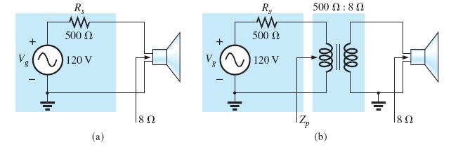
29 EXAMPLE 5 a. The source impedance for the supply in Figure (a) is 500Ω, which is a poor match with the 8Ω input impedance of the speaker. You can expect only that the power delivered to the speaker will be significantly less than the maximum possible level. Determine the power to the speaker under the conditions in Figure(a). b. In Figure (b), a commercially available 500Ω to 8Ω audio impedance matching transformer was introduced between the speaker and the source. Determine the input impedance of the transformer and the power delivered to the speaker. c. Compare the power delivered to the speaker under the conditions of parts (a) and (b). d. Find the approximate turns ratio for the transformer.
30 Solutions:
31 b. Since the input impedance of the transformer matches that of the source, maximum power transfer conditions have been established, and the source current is now determined by The power to the primary (which equals that to the secondary for the ideal transformer) is The result is not in milli-watts, as obtained above, and exceeds 7 W, which is a significant improvement.
32 c. Comparing levels, we see that 7.2 W/446.3 mw = 16.1, or more than 16 times the power is delivered to the speaker using the impedance matching transformer.
 Equivalent circuit for")

33 EQUIVALENT CIRCUIT (IRON-CORE TRANSFORMER) Equivalent circuit for the practical iron-core transformer. Identifying the leakage flux of the primary.
34 Rp and Rs are simply the dc resistance of the primary and secondary windings. Rc represents the hysteresis and eddy current losses (core losses) within the core due to an ac flux through the core. The inductance Lm (magnetizing inductance) is the inductance associated with the magnetization of the core, that is, the establishing of the flux m in the core. Cp the lumped capacitances of the primary Cs the lumped capacitances of secondary circuits. Cw represents the equivalent lumped capacitances between the windings of the transformer.
35 Reduced equivalent circuit for the nonideal iron-core transformer.
36 If we now reflect the secondary circuit through the ideal transformer, as shown in Figure (a), we will have the load and generator voltage in the same continuous circuit. Reflecting the secondary circuit into the primary side of the iron-core transformer.
 through")
37 which result in the useful equivalent circuit of Figure(b). The load voltage can be obtained directly from the circuit in Figure (b) through the voltage divider rule:
 and (b) lagging power-factor load (inductive).")
38 Phasor diagram for the iron-core transformer Phasor diagram for the iron-core transformer with (a) unity powerfactor load (resistive) and (b) lagging power-factor load (inductive). Draw phasor diagram with lead power factor
 if Re and Xe = 0. Compare with the result of part (b).")
39 EXAMPLE 6 For a transformer having the equivalent circuit in Figure a. Determine Re and Xe. b. Determine the magnitude of the voltages VL and Vg. c. Determine the magnitude of the voltage Vg to establish the same load voltage in part (b) if Re and Xe = 0. Compare with the result of part (b).
40 b. The transformed equivalent circuit appears in the following Figure
41 Therefore, it is necessary to increase the generator voltage by V (due to Re and Xe) to obtain the same load voltage.
42 HIGH FREQUENCY EQUIVLENT CIRCUIT For higher frequencies, the capacitive elements and primary and secondary leakage reactances must be considered, as shown in Figure. the effects of Cw and Cs appear as a lumped capacitor C in the reflected network and Cp does not appear since the effect of C predominates. High-frequency reflected equivalent circuit.

43 SERIES CONNECTION OF MUTUALLY COUPLED COILS 1.Mutually coupled coils connected in series with positive mutual inductance.
44 and, similarly, For the series connection, the total induced voltage across the series coils, represented by et, is and the total effective inductance is The subscript (+) was included to indicate that the mutual terms have a positive sign and are added to the self-inductance values to determine the total inductance.

45 If the coils are wound such as shown in the following Figure, where 1 and 2 are in opposition, the induced voltages due to the mutual terms oppose that due to the self-inductance, and the total inductance is determined by Mutually coupled coils connected in series with negative mutual inductance. The mutual inductance can be determined by: the mutual inductance is equal to one-quarter the difference between the total inductance with a positive and negative mutual effect.
46 On a network schematic where it is inconvenient to indicate the windings and the flux path, a system of dots is used that determines whether the mutual terms are to be positive or negative. The dot convention is shown in the following Figure for the series coils. If the current through each of the mutually coupled coils is going away from (or toward) the dot as it passes through the coil, the mutual term will be positive, as shown for the case in Figure (a). If the arrow indicating current direction through the coil is leaving the dot for one coil and entering the dot for the other, the mutual term is negative.
47 When determining the sign, be sure to examine the current direction within the coil itself. In Figure (b), one direction is indicated outside for one coil and through for the other. It initially may appear that the sign should be positive since both currents enter the dot, but the current through coil 1 is leaving the dot; hence a negative sign is in order.

48 2. Mutually coupled coils connected in series with negative mutual inductance. The total mutual inductance
49 EXAMPLE 8 Find the total inductance of the series coils in Figure. Solution:
50 EXAMPLE 9 Write the mesh equations for the transformer network in Figure.

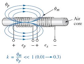
51 AIR-CORE TRANSFORMER As the name implies, the air-core transformer does not have a ferromagnetic core to link the primary and secondary coils. Rather, the coils are placed sufficiently close to have a mutual inductance that establishes the desired transformer action. Air-core transformer equivalent circuit.

52 Input characteristics for the air-core transformer.

53 EXAMPLE 10 Determine the input impedance to the air-core transformer in Figure.
54
55 APPLICATIONS Write about one of the following: Soldering Gun Low-Voltage Compensation Ballast Transformer Recent Developments
Transformers 21.1 INTRODUCTION 21.2 MUTUAL INDUCTANCE
 21 Transformers 21.1 INTRODUCTION Chapter 12 discussed the self-inductance of a coil. We shall now examine the mutual inductance that exists between coils of the same or different dimensions. Mutual inductance
13. Magnetically Coupled Circuits
 13. Magnetically Coupled Circuits The change in the current flowing through an inductor induces (creates) a voltage in the conductor itself (self-inductance) and in any nearby conductors (mutual inductance)
ESO 210 Introduction to Electrical Engineering
 ESO 210 Introduction to Electrical Engineering Lecture-19 Magnetic Circuits and Introduction to Transformers 2 SERIES CONNECTION OF MUTUALLY COUPLED COILS A mutual term will alter the total inductance
Chapter 16: Mutual Inductance
 Chapter 16: Mutual Inductance Instructor: Jean-François MILLITHALER http://faculty.uml.edu/jeanfrancois_millithaler/funelec/spring2017 Slide 1 Mutual Inductance When two coils are placed close to each
EE 221 Circuits II. Chapter 13 Magnetically Coupled Circuits
 EE Circuits II Chapter 3 Magnetically Coupled Circuits Magnetically Coupled Circuits 3. What is a transformer? 3. Mutual Inductance 3.3 Energy in a Coupled Circuit 3.4 inear Transformers 3.5 Ideal Transformers
ELECTRICAL TECHNOLOGY EET 103/4
 ELECTRICAL TECHNOLOGY EET 103/4 Define and analyze the rincile of transformer, its arameters and structure. Describe and analyze Ideal transformer, equivalent circuit, and hasor diagram Calculate and justify
Review: Lecture 9. Instantaneous and Average Power. Effective or RMS Value. Apparent Power and Power Factor. Complex Power. Conservation of AC Power
 Review: Lecture 9 Instantaneous and Average Power p( t) VmI m cos ( v i ) VmI m cos ( t v i ) Maximum Average Power Transfer Z L R L jx Effective or RMS Value I rms I m L R P * TH Apparent Power and Power
PHYS 1442 Section 004 Lecture #15
 PHYS 1442 Section 004 Lecture #15 Monday March 17, 2014 Dr. Andrew Brandt Chapter 21 Generator Transformer Inductance 3/17/2014 1 PHYS 1442-004, Dr. Andrew Brandt Announcements HW8 on Ch 21-22 will be
CHAPTER 2. Transformers. Dr Gamal Sowilam
 CHAPTER Transformers Dr Gamal Sowilam Introduction A transformer is a static machine. It is not an energy conversion device, it is indispensable in many energy conversion systems. A transformer essentially
Chapter 13 Magnetically Coupled Circuits. Chapter Objectives:
 Chapter 13 Magnetically Coupled Circuits Chapter Objectives: Understand magnetically coupled circuits. Learn the concept of mutual inductance. Be able to determine energy in a coupled circuit. Learn how
Unit-4. Magnetic Circuits
 Unit-4 Magnetic Circuits Topics to be Discussed Magnetic Coupling. Coefficient of Coupling (k). Sign of Mutual Voltage. Dot Convention. September 9, 0 Magnetic Circuits Magnetically Coupled Circuits A
EE2003 Circuit Theory Chapter 13 Magnetically Coupled Circuits
 EE003 Circuit Theory Chapter 3 Magnetically Coupled Circuits Copyright The McGraw-Hill Companies, Inc. Permission required for reproduction or display. Magnetically Coupled Circuit Chapter 3 3. What is
UNIVERSITY OF TECHNOLOGY By: Fadhil A. Hasan ELECTRICAL MACHINES
 UNIVERSITY OF TECHNOLOGY DEPARTMENT OF ELECTRICAL ENGINEERING Year: Second 2016-2017 By: Fadhil A. Hasan ELECTRICAL MACHINES І Module-II: AC Transformers o Single phase transformers o Three-phase transformers
An induced emf is the negative of a changing magnetic field. Similarly, a self-induced emf would be found by
 This is a study guide for Exam 4. You are expected to understand and be able to answer mathematical questions on the following topics. Chapter 32 Self-Induction and Induction While a battery creates an
Chapt ha e pt r e r 11 Inductors
 Chapter 11 Inductors The Basic Inductor When a length of wire is formed onto a coil, it becomes a basic inductor Magnetic lines of force around each loop in the winding of the coil effectively add to the
Look over Chapter 31 sections 1-4, 6, 8, 9, 10, 11 Examples 1-8. Look over Chapter 21 sections Examples PHYS 2212 PHYS 1112
 PHYS 2212 Look over Chapter 31 sections 1-4, 6, 8, 9, 10, 11 Examples 1-8 PHYS 1112 Look over Chapter 21 sections 11-14 Examples 16-18 Good Things To Know 1) How AC generators work. 2) How to find the
PHYS 1441 Section 001 Lecture #22 Wednesday, Nov. 29, 2017
 PHYS 1441 Section 001 Lecture #22 Chapter 29:EM Induction & Faraday s Law Transformer Electric Field Due to Changing Magnetic Flux Chapter 30: Inductance Mutual and Self Inductance Energy Stored in Magnetic
Department of Electrical and Computer Engineering Lab 6: Transformers
 ESE Electronics Laboratory A Department of Electrical and Computer Engineering 0 Lab 6: Transformers. Objectives ) Measure the frequency response of the transformer. ) Determine the input impedance of
PHYS 1444 Section 501 Lecture #20
 PHYS 1444 Section 501 Lecture #0 Monday, Apr. 17, 006 Transformer Generalized Faraday s Law Inductance Mutual Inductance Self Inductance Inductor Energy Stored in the Magnetic Field 1 Announcements Quiz
RC circuit. Recall the series RC circuit.
 RC circuit Recall the series RC circuit. If C is discharged and then a constant voltage V is suddenly applied, the charge on, and voltage across, C is initially zero. The charge ultimately reaches the
Electric Circuits II Magnetically Coupled Circuits. Dr. Firas Obeidat
 Electric Circuits II Magnetically Coupled Circuits Dr. Firas Obeidat 1 Table of contents 1 Mutual Inductance 2 Dot Convention 3 Analyze Circuits Involving Mutual Inductance 4 Energy in a Coupled Circuit
Chapter 2-1 Transformers
 Principles of Electric Machines and Power Electronics Chapter 2-1 Transformers Third Edition P. C. Sen Transformer application 1: power transmission Ideal Transformer Assumptions: 1. Negligible winding
Practical Transformer on Load
 Practical Transformer on Load We now consider the deviations from the last two ideality conditions : 1. The resistance of its windings is zero. 2. There is no leakage flux. The effects of these deviations
APPLICATION NOTE - 018
 APPLICATION NOTE - 018 Power Transformers Background Power Transformers are used within an AC power distribution systems to increase or decrease the operating voltage to achieve the optimum transmission
TRANSFORMER THEORY. Mutual Induction
 Transformers Transformers are used extensively for AC power transmissions and for various control and indication circuits. Knowledge of the basic theory of how these components operate is necessary to
Inductance in DC Circuits
 Inductance in DC Circuits Anurag Srivastava Concept: Inductance is characterized by the behavior of a coil of wire in resisting any change of electric current through the coil. Arising from Faraday's law,
Chapter 33. Alternating Current Circuits
 Chapter 33 Alternating Current Circuits Alternating Current Circuits Electrical appliances in the house use alternating current (AC) circuits. If an AC source applies an alternating voltage to a series
EE2022 Electrical Energy Systems
 EE0 Electrical Energy Systems Lecture : Transformer and Per Unit Analysis 7-0-0 Panida Jirutitijaroen Department of Electrical and Computer Engineering /9/0 EE0: Transformer and Per Unit Analysis by P.
PHYSICS WORKSHEET CLASS : XII. Topic: Alternating current
 PHYSICS WORKSHEET CLASS : XII Topic: Alternating current 1. What is mean by root mean square value of alternating current? 2. Distinguish between the terms effective value and peak value of an alternating
Transformers. gpmacademics.weebly.com
 TRANSFORMERS Syllabus: Principles of operation, Constructional Details, Losses and efficiency, Regulation of Transformer, Testing: OC & SC test. TRANSFORMER: It is a static device which transfers electric
Chapter 7. Copyright The McGraw-Hill Companies, Inc. Permission required for reproduction or display.
 Chapter 7 Copyright The McGraw-Hill Companies, Inc. Permission required for reproduction or display. Learning Objectives 1. Understand the meaning of instantaneous and average power, master AC power notation,
EE 340 Power Transformers
 EE 340 Power Transformers Preliminary considerations A transformer is a device that converts one AC voltage to another AC voltage at the same frequency. It consists of one or more coil(s) of wire wrapped
Electromagnetic Induction
 Chapter 16 Electromagnetic Induction In This Chapter: Electromagnetic Induction Faraday s Law Lenz s Law The Transformer Self-Inductance Inductors in Combination Energy of a Current-Carrying Inductor Electromagnetic
In this lecture. Electromagnetism. Electromagnetism. Oersted s Experiment. Electricity & magnetism are different aspects of the same basic phenomenon:
 In this lecture Electromagnetism Electromagnetic Effect Electromagnets Electromechanical Devices Transformers Electromagnetic Effect Electricity & magnetism are different aspects of the same basic phenomenon:
Chapter 33. Alternating Current Circuits
 Chapter 33 Alternating Current Circuits C HAP T E O UTLI N E 33 1 AC Sources 33 2 esistors in an AC Circuit 33 3 Inductors in an AC Circuit 33 4 Capacitors in an AC Circuit 33 5 The L Series Circuit 33
Electrical Theory 2 Lessons for Fall Semester:
 Electrical Theory 2 Lessons for Fall Semester: Lesson 1 Magnetism Lesson 2 Introduction to AC Theory Lesson 3 Lesson 4 Capacitance and Capacitive Reactance Lesson 5 Impedance and AC Circuits Lesson 6 AC
WELCOME TO THE LECTURE
 WLCOM TO TH LCTUR ON TRNFORMR Single Phase Transformer Three Phase Transformer Transformer transformer is a stationary electric machine which transfers electrical energy (power) from one voltage level
Transformers. Objectives
 Transformers Objectives Explain mutual inductance Describe how a transformer is constructed and how it works Explain how a step-up transformer works Explain how a step-down transformer works Discuss the
ET1210: Module 5 Inductance and Resonance
 Part 1 Inductors Theory: When current flows through a coil of wire, a magnetic field is created around the wire. This electromagnetic field accompanies any moving electric charge and is proportional to
N I N LI I. I t. (Note how L is independent of the current I.)
") UNIT- IV MAGNETICALLY COUPLED CIRCUITS Magnetically Coupled Circuits: Self inductance - Mutual inductance - Dot rule - Coefficient of coupling - Analysis of multi winding coupled circuits - Series, Parallel
UNIT- IV MAGNETICALLY COUPLED CIRCUITS Magnetically Coupled Circuits: Self inductance - Mutual inductance - Dot rule - Coefficient of coupling - Analysis of multi winding coupled circuits - Series, Parallel
PART B. t (sec) Figure 1
 Figure 1") Code No: R16128 R16 SET 1 I B. Tech II Semester Regular Examinations, April/May 217 ELECTRICAL CIRCUIT ANALYSIS I (Electrical and Electronics Engineering) Time: 3 hours Max. Marks: 7 Note: 1. Question
Code No: R16128 R16 SET 1 I B. Tech II Semester Regular Examinations, April/May 217 ELECTRICAL CIRCUIT ANALYSIS I (Electrical and Electronics Engineering) Time: 3 hours Max. Marks: 7 Note: 1. Question
CHAPTER 2. Basic Concepts, Three-Phase Review, and Per Unit
 CHAPTER 2 Basic Concepts, Three-Phase Review, and Per Unit 1 AC power versus DC power DC system: - Power delivered to the load does not fluctuate. - If the transmission line is long power is lost in the
1. If the flux associated with a coil varies at the rate of 1 weber/min,the induced emf is
 1. f the flux associated with a coil varies at the rate of 1 weber/min,the induced emf is 1 1. 1V 2. V 60 3. 60V 4. Zero 2. Lenz s law is the consequence of the law of conservation of 1. Charge 2. Mass
Experiment 9: AC circuits
 Experiment 9: AC circuits Nate Saffold nas2173@columbia.edu Office Hour: Mondays, 5:30PM-6:30PM @ Pupin 1216 INTRO TO EXPERIMENTAL PHYS-LAB 1493/1494/2699 Introduction Last week (RC circuit): This week:
Faraday Laws of Electromagnetic Induction CLIL LESSON
 Faraday Laws of Electromagnetic Induction CLIL LESSON Experimental trials Michael Faraday-1931 This law shows the relationship between electric circuit and magnetic field A coil is connected to a galvanometer
Cornerstone Electronics Technology and Robotics Week 32 Transformers
 Cornerstone Electronics Technology and Robotics Week 32 Transformers Administration: o Prayer o Turn in quiz Electricity and Electronics, Section 12.1, Transformer Theory: o A transformer is a device that
Review 6. unlike poles cause the magnets to attract. like poles cause the magnets to repel.
 Review 6 1. The two characteristics of all magnets are: they attract and hold Iron, and, if free to move, they will assume roughly a south - north position. 2. Lines of flux always leave the north pole
Walchand Institute of Technology. Basic Electrical and Electronics Engineering. Transformer
 Walchand Institute of Technology Basic Electrical and Electronics Engineering Transformer 1. What is transformer? explain working principle of transformer. Electrical power transformer is a static device
Electrical Machines I : Transformers
 UNIT TRANSFORMERS PART A (Q&A) 1. What is step down transformer? The transformer used to step down the voltage from primary to secondary is called as step down transformer. (Ex: /11).. Draw the noload
AC Power Instructor Notes
 Chapter 7: AC Power Instructor Notes Chapter 7 surveys important aspects of electric power. Coverage of Chapter 7 can take place immediately following Chapter 4, or as part of a later course on energy
Table of Contents. Table of Figures. Table of Tables
 Abstract The aim of this report is to investigate and test a transformer and check if it is good to use by doing the following tests continuity test, insulation test, polarity test, open circuit test,
Properties of Inductor and Applications
 LABORATORY Experiment 3 Properties of Inductor and Applications 1. Objectives To investigate the properties of inductor for different types of magnetic material To calculate the resonant frequency of a
Reg. No. : BASIC ELECTRICAL TECHNOLOGY (ELE 101)
") Department of Electrical and Electronics Engineering Reg. No. : MNIPL INSTITUTE OF TECHNOLOGY, MNIPL ( Constituent Institute of Manipal University, Manipal) FIRST SEMESTER B.E. DEGREE MKEUP EXMINTION (REVISED
Department of Electrical and Electronics Engineering Reg. No. : MNIPL INSTITUTE OF TECHNOLOGY, MNIPL ( Constituent Institute of Manipal University, Manipal) FIRST SEMESTER B.E. DEGREE MKEUP EXMINTION (REVISED
PESIT Bangalore South Campus Hosur road, 1km before Electronic City, Bengaluru -100 Department of Electronics & Communication Engineering
 CONTINUOUS INTERNAL EVALUATION TEST -1 Date : 27/2/2018 Marks:60 Subject & Code : Basic Electrical Engineering, 17ELE25 Section: A,B,C,D,E Time : 8:30 am 11:30 a.m Name of faculty: Mrs. Dhanashree Bhate,
3. What is hysteresis loss? Also mention a method to minimize the loss. (N-11, N-12)
") DHANALAKSHMI COLLEGE OF ENGINEERING, CHENNAI DEPARTMENT OF ELECTRICAL AND ELECTRONICS ENGINEERING EE 6401 ELECTRICAL MACHINES I UNIT I : MAGNETIC CIRCUITS AND MAGNETIC MATERIALS Part A (2 Marks) 1. List
DHANALAKSHMI COLLEGE OF ENGINEERING, CHENNAI DEPARTMENT OF ELECTRICAL AND ELECTRONICS ENGINEERING EE 6401 ELECTRICAL MACHINES I UNIT I : MAGNETIC CIRCUITS AND MAGNETIC MATERIALS Part A (2 Marks) 1. List
ELECTROMAGNETIC INDUCTION AND ALTERNATING CURRENT (Assignment)
") ELECTROMAGNETIC INDUCTION AND ALTERNATING CURRENT (Assignment) 1. In an A.C. circuit A ; the current leads the voltage by 30 0 and in circuit B, the current lags behind the voltage by 30 0. What is the
ELECTROMAGNETIC INDUCTION AND ALTERNATING CURRENT (Assignment) 1. In an A.C. circuit A ; the current leads the voltage by 30 0 and in circuit B, the current lags behind the voltage by 30 0. What is the
EEE 202 ELECTRO-TECHNIC LAB. PART 7 THEORY
 EEE 0 ELECTRO-TECHNIC LAB. PART 7 THEORY Yrd. Doç. Dr. Serhan Yarkan Arş. Gör. Dilara Albayrak İSTANBUL COMMERCE UNIVERSITY Contents EXAMINATION OF LC FILTERS... 0.1 INTRODUCTION... EXAMINATION OF TRANSFORMER...
Chapter 11. Alternating Current
 Unit-2 ECE131 BEEE Chapter 11 Alternating Current Objectives After completing this chapter, you will be able to: Describe how an AC voltage is produced with an AC generator (alternator) Define alternation,
FGJTCFWP"KPUVKVWVG"QH"VGEJPQNQI[" FGRCTVOGPV"QH"GNGEVTKECN"GPIKPGGTKPI" VGG"246"JKIJ"XQNVCIG"GPIKPGGTKPI
 FGJTFWP"KPUKWG"QH"GEJPQNQI[" FGRTOGP"QH"GNGETKEN"GPIKPGGTKPI" GG"46"JKIJ"XQNIG"GPIKPGGTKPI Resonant Transformers: The fig. (b) shows the equivalent circuit of a high voltage testing transformer (shown
Exclusive Technology Feature. Leakage Inductance (Part 1): Friend Or Foe? The Underlying Physics. ISSUE: October 2015
: Friend Or Foe? The Underlying Physics. ISSUE: October 2015") ISSUE: October 2015 Leakage Inductance (Part 1): Friend Or Foe? by Ernie Wittenbreder, Technical Witts, Flagstaff, Ariz There are situations in which leakage inductance in a transformer or coupled inductor
ISSUE: October 2015 Leakage Inductance (Part 1): Friend Or Foe? by Ernie Wittenbreder, Technical Witts, Flagstaff, Ariz There are situations in which leakage inductance in a transformer or coupled inductor
86 chapter 2 Transformers
 86 chapter 2 Transformers Wb 1.2x10 3 0 1/60 2/60 3/60 4/60 5/60 6/60 t (sec) 1.2x10 3 FIGURE P2.2 2.3 A single-phase transformer has 800 turns on the primary winding and 400 turns on the secondary winding.
Sensors and Actuators Introduction to sensors
 Sensors and Actuators Introduction to sensors Sander Stuijk (s.stuijk@tue.nl) Department of Electrical Engineering Electronic Systems INDUCTIVE SENSORS (Chapter 3.4, 7.3) 3 Inductive sensors 4 Inductive
SECTION 4 TRANSFORMERS. Yilu (Ellen) Liu. Associate Professor Electrical Engineering Department Virginia Tech University
 Liu. Associate Professor Electrical Engineering Department Virginia Tech University") SECTION 4 TRANSFORMERS Yilu (Ellen) Liu Associate Professor Electrical Engineering Department Virginia Tech University Analysis of Transformer Turns Ratio......................... 4.2 Analysis of a Step-Up
SECTION 4 TRANSFORMERS Yilu (Ellen) Liu Associate Professor Electrical Engineering Department Virginia Tech University Analysis of Transformer Turns Ratio......................... 4.2 Analysis of a Step-Up
ELECTRICAL ENGINEERING ESE TOPIC WISE OBJECTIVE SOLVED PAPER-II
 ELECTRICAL ENGINEERING ESE TOPIC WISE OBJECTIVE SOLVED PAPER-II From (1992 2017) Office : F-126, (Lower Basement), Katwaria Sarai, New Delhi-110016 Phone : 011-26522064 Mobile : 8130909220, 9711853908
QUESTION BANK ETE (17331) CM/IF. Chapter1: DC Circuits
 CM/IF. Chapter1: DC Circuits") QUESTION BANK ETE (17331) CM/IF Chapter1: DC Circuits Q1. State & explain Ohms law. Also explain concept of series & parallel circuit with the help of diagram. 3M Q2. Find the value of resistor in fig.
QUESTION BANK ETE (17331) CM/IF Chapter1: DC Circuits Q1. State & explain Ohms law. Also explain concept of series & parallel circuit with the help of diagram. 3M Q2. Find the value of resistor in fig.
CHAPTER 9. Sinusoidal Steady-State Analysis
 CHAPTER 9 Sinusoidal Steady-State Analysis 9.1 The Sinusoidal Source A sinusoidal voltage source (independent or dependent) produces a voltage that varies sinusoidally with time. A sinusoidal current source
Module 1. Introduction. Version 2 EE IIT, Kharagpur
 Module 1 Introduction Lesson 1 Introducing the Course on Basic Electrical Contents 1 Introducing the course (Lesson-1) 4 Introduction... 4 Module-1 Introduction... 4 Module-2 D.C. circuits.. 4 Module-3
Transformer. V1 is 1.0 Vp-p at 10 Khz. William R. Robinson Jr. p1of All rights Reserved
 V1 is 1.0 Vp-p at 10 Khz Step Down Direction Step Up Direction William R. Robinson Jr. p1of 24 Purpose To main purpose is to understand the limitations of the B2Spice simulator transformer model that I
Radar. Radio. Electronics. Television. .104f 4E011 UNITED ELECTRONICS LABORATORIES LOUISVILLE
 Electronics Radio Television.104f Radar UNITED ELECTRONICS LABORATORIES LOUISVILLE KENTUCKY REVISED 1967 4E011 1:1111E111611 COPYRIGHT 1956 UNITED ELECTRONICS LABORATORIES POWER SUPPLIES ASSIGNMENT 23
Aligarh College of Engineering & Technology (College Code: 109) Affiliated to UPTU, Approved by AICTE Electrical Engg.
 Affiliated to UPTU, Approved by AICTE Electrical Engg.") Aligarh College of Engineering & Technology (College Code: 19) Electrical Engg. (EE-11/21) Unit-I DC Network Theory 1. Distinguish the following terms: (a) Active and passive elements (b) Linearity and
Aligarh College of Engineering & Technology (College Code: 19) Electrical Engg. (EE-11/21) Unit-I DC Network Theory 1. Distinguish the following terms: (a) Active and passive elements (b) Linearity and
Alternating current circuits- Series RLC circuits
 FISI30 Física Universitaria II Professor J.. ersosimo hapter 8 Alternating current circuits- Series circuits 8- Introduction A loop rotated in a magnetic field produces a sinusoidal voltage and current.
Power Electronics. Prof. B. G. Fernandes. Department of Electrical Engineering. Indian Institute of Technology, Bombay.
 Power Electronics Prof. B. G. Fernandes Department of Electrical Engineering Indian Institute of Technology, Bombay Lecture - 28 So far we have studied 4 different DC to DC converters. They are; first
UNIT II MEASUREMENT OF POWER & ENERGY
 UNIT II MEASUREMENT OF POWER & ENERGY Dynamometer type wattmeter works on a very simple principle which is stated as "when any current carrying conductor is placed inside a magnetic field, it experiences
ECE 241L Fundamentals of Electrical Engineering. Experiment 8 A-C Transformer, Magnetization & Hysteresis
 ECE 241L Fundamentals of Electrical Engineering Experiment 8 A-C Transformer, Magnetization & Hysteresis A. Objectives: I. Measure leakage inductance and resistance loss II. Measure magnetization inductance
JEFFERSON COLLEGE COURSE SYLLABUS ETC104 AC CIRCUITS. 5 Credit Hours. Prepared by: Ronald S. Krive. Revised Date: October 2007 by Dennis Eimer
 JEFFERSON COLLEGE COURSE SYLLABUS ETC104 AC CIRCUITS 5 Credit Hours Prepared by: Ronald S. Krive Revised Date: October 2007 by Dennis Eimer Division of Technology Dr. John Keck, Dean Ms. Brenda Russell,
CHAPTER 4. Distribution Transformers
 CHAPTER 4 Distribution Transformers Introduction A transformer is an electrical device that transfers energy from one circuit to another purely by magnetic coupling. Relative motion of the parts of the
~=E.i!=h. Pre-certification Transformers
 7 Transformers Section 26 of the electrical code governs the use and installations of transformers. A transformer is a static device used to transfer energy from one alternating current circuit to another.
Glossary of Common Magnetic Terms
 Glossary of Common Magnetic Terms Copyright by Magnelab, Inc. 2009 Air Core A term used when no ferromagnetic core is used to obtain the required magnetic characteristics of a given coil. (see Core) Ampere
UNIT 1 CIRCUIT ANALYSIS 1 What is a graph of a network? When all the elements in a network is replaced by lines with circles or dots at both ends.
 UNIT 1 CIRCUIT ANALYSIS 1 What is a graph of a network? When all the elements in a network is replaced by lines with circles or dots at both ends. 2 What is tree of a network? It is an interconnected open
K. MAHADEVAN. Professor Electrical and Electronics Engineering PSNA College of Engineering and Technology Dindigul, Tamil Nadu C.
 Electrical Circuit Analysis K. MAHADEVAN Professor Electrical and Electronics Engineering PSNA College of Engineering and Technology Dindigul, Tamil Nadu C. CHITRA Professor Electronics and Communication
Class XII Chapter 7 Alternating Current Physics
 Question 7.1: A 100 Ω resistor is connected to a 220 V, 50 Hz ac supply. (a) What is the rms value of current in the circuit? (b) What is the net power consumed over a full cycle? Resistance of the resistor,
Electrical Engineering / Electromagnetics
 Electrical Engineering / Electromagnetics. Plot voltage versus time and current versus time for the circuit with the following substitutions: A. esistor B. Capacitor C. Inductor t = 0 A/B/C A. I t t B.
Module 7. Transformer. Version 2 EE IIT, Kharagpur
 Module 7 Transformer Lesson 28 Problem solving on Transformers Contents 28 Problem solving on Transformer (Lesson-28) 4 28.1 Introduction. 4 28.2 Problems on 2 winding single phase transformers. 4 28.3
PHYS 1444 Section 003 Lecture #19
 PHYS 1444 Section 003 Lecture #19 Monday, Nov. 14, 2005 Electric Generators DC Generator Eddy Currents Transformer Mutual Inductance Today s homework is homework #10, due noon, next Tuesday!! 1 Announcements
By Gill ( ) PDF created with FinePrint pdffactory trial version
 PDF created with FinePrint pdffactory trial version") By Gill (www.angelfire.com/al4/gill ) 1 Introduction One of the main reasons of adopting a.c. system instead of d.c. for generation, transmission and distribution of electrical power is that alternatin
By Gill (www.angelfire.com/al4/gill ) 1 Introduction One of the main reasons of adopting a.c. system instead of d.c. for generation, transmission and distribution of electrical power is that alternatin
VOLTECHNOTES. Turns Ratio iss 4 Page 1 of 7
 VOLTECHNOTES Turns Ratio 104-113 iss 4 Page 1 of 7 Introduction Transformers are used in a wide array of electrical or electronic applications, providing functions that range from isolation and stepping
Generalized Theory Of Electrical Machines
 Essentials of Rotating Electrical Machines Generalized Theory Of Electrical Machines All electrical machines are variations on a common set of fundamental principles, which apply alike to dc and ac types,
The power transformer
 ELEC0014 - Introduction to power and energy systems The power transformer Thierry Van Cutsem t.vancutsem@ulg.ac.be www.montefiore.ulg.ac.be/~vct November 2017 1 / 35 Power transformers are used: to transmit
TRANSFORMERS INTRODUCTION
 Tyco Electronics Corporation Crompton Instruments 1610 Cobb International Parkway, Unit #4 Kennesaw, GA 30152 Tel. 770-425-8903 Fax. 770-423-7194 TRANSFORMERS INTRODUCTION A transformer is a device that
SHRI RAMSWAROOP MEMORIAL COLLEGE OF ENGG. & MANAGEMENT B.Tech. [SEM I (EE, EN, EC, CE)] QUIZ TEST-3 (Session: ) Time: 1 Hour ELECTRICAL ENGINEE
![SHRI RAMSWAROOP MEMORIAL COLLEGE OF ENGG. & MANAGEMENT B.Tech. [SEM I (EE, EN, EC, CE)] QUIZ TEST-3 (Session: ) Time: 1 Hour ELECTRICAL ENGINEE](/thumbs/94/118213481.jpg "SHRI RAMSWAROOP MEMORIAL COLLEGE OF ENGG. & MANAGEMENT B.Tech. [SEM I (EE, EN, EC, CE)] QUIZ TEST-3 (Session: ) Time: 1 Hour ELECTRICAL ENGINEE") SHRI RAMSWAROOP MEMORIAL COLLEGE OF ENGG. & MANAGEMENT B.Tech. [SEM I (EE, EN, EC, CE)] QUIZ TEST-3 (Session: 2014-15) Time: 1 Hour ELECTRICAL ENGINEERING Max. Marks: 30 (NEE-101) Roll No. Academic/26
SHRI RAMSWAROOP MEMORIAL COLLEGE OF ENGG. & MANAGEMENT B.Tech. [SEM I (EE, EN, EC, CE)] QUIZ TEST-3 (Session: 2014-15) Time: 1 Hour ELECTRICAL ENGINEERING Max. Marks: 30 (NEE-101) Roll No. Academic/26
1 K Hinds 2012 TRANSFORMERS
 1 K Hinds 2012 TRANSFORMERS A transformer changes electrical energy of a given voltage into electrical energy at a different voltage level. It consists of two coils which are not electrically connected,
PROBLEMS on Transformers
 PROBLEMS on Transformers (A) Simple Problems 1. A single-phase, 250-kVA, 11-kV/415-V, 50-Hz transformer has 80 turns on the secondary. Calculate (a) the approximate values of the primary and secondary
Spring 2000 EE361: MIDTERM EXAM 1
 NAME: STUDENT NUMBER: Spring 2000 EE361: MIDTERM EXAM 1 This exam is open book and closed notes. Assume f=60 hz and use the constant µ o =4π 10-7 wherever necessary. Be sure to show all work clearly. 1.
El-Hawary, M.E. The Transformer Electrical Energy Systems. Series Ed. Leo Grigsby Boca Raton: CRC Press LLC, 2000
 El-Hawary, M.E. The Transformer Electrical Energy Systems. Series Ed. Leo Grigsby Boca Raton: CRC Press LLC, 000 97 Chapter 4 THE TRANSFORMER 4. NTRODUCTON The transformer is a valuable apparatus in electrical
Transformer & Induction M/C
 UNIT- 2 SINGLE-PHASE TRANSFORMERS 1. Draw equivalent circuit of a single phase transformer referring the primary side quantities to secondary and explain? (July/Aug - 2012) (Dec 2012) (June/July 2014)
 VIDYARTHIPLUS - ANNA UNIVERSITY ONLINE STUDENTS COMMUNITY UNIT 1 DC MACHINES PART A 1. State Faraday s law of Electro magnetic induction and Lenz law. 2. Mention the following functions in DC Machine (i)
Electronic Measurements & Instrumentation. 1. Draw the Maxwell s Bridge Circuit and derives the expression for the unknown element at balance?
 UNIT -6 1. Draw the Maxwell s Bridge Circuit and derives the expression for the unknown element at balance? Ans: Maxwell's bridge, shown in Fig. 1.1, measures an unknown inductance in of standard arm offers
Unit 3 Magnetism...21 Introduction The Natural Magnet Magnetic Polarities Magnetic Compass...21
 Chapter 1 Electrical Fundamentals Unit 1 Matter...3 Introduction...3 1.1 Matter...3 1.2 Atomic Theory...3 1.3 Law of Electrical Charges...4 1.4 Law of Atomic Charges...4 Negative Atomic Charge...4 Positive
Laminate Transformer Testing
 1. Introduction: Laminate transformers are mostly used as line frequency, low frequency and low/high voltage step-up, step-down transformers. Two coils are wound over a core such that they are magnetically
Preface...x Chapter 1 Electrical Fundamentals
 Preface...x Chapter 1 Electrical Fundamentals Unit 1 Matter...3 Introduction...3 1.1 Matter...3 1.2 Atomic Theory...3 1.3 Law of Electrical Charges...4 1.4 Law of Atomic Charges...5 Negative Atomic Charge...5