UNIT II MEASUREMENT OF POWER & ENERGY
|
|
|
- Jerome Clinton Sharp
- 6 years ago
- Views:
Transcription
1 UNIT II MEASUREMENT OF POWER & ENERGY Dynamometer type wattmeter works on a very simple principle which is stated as "when any current carrying conductor is placed inside a magnetic field, it experiences a mechanical force and due to this mechanical force, deflection of conductor takes place." Construction It consists of the following parts: Moving coil - Moving coil moves the pointer with the help of spring control instrument. A limited amount of current flows through the moving coil so as to avoid heating. So in order to limit the current we have connected the high value resistor in series with the moving coil. The moving is air cored and is mounted on a pivoted spindle and can moves freely. In electrodynamometer type wattmeter, moving coil works as pressure coil. Hence moving coil is connected across the voltage and thus the current flowing through this coil is always proportional to the voltage. Fixed coil - The fixed coil is divided into two equal parts and these are connected in series with the load, therefore the load current will flow through these coils. Now the reason is very obvious of using two fixed coils instead of one, so that it can be constructed to carry considerable amount of electric current. These coils are called the current coils of electrodynamometer type wattmeter. Earlier these fixed coils are designed to carry the current of about 100 amperes but now the modern wattmeter are designed to carry current of about 20 amperes in order to save power. Control system - Out of two controlling systems i.e. gravity control and spring control, only spring controlled systems are used in these types of wattmeter. Gravity controlled system cannot be employed because they will contain appreciable amount of errors. Damping system - Air friction damping is used, as eddy current damping will distort the weak operating magnetic field and thus it may lead to error. Scale - There is uniform scale is used in these types of instrument as moving coil moves linearly over a range of 40 degrees to 50 degrees on either sides. Working of Dynamometer type wattmeter: When power is to be measured in a circuit, the instrument is suitably connected in the circuit. The current coil is connected in series with load so that it carries the circuit current. The potential coil is connected across the load so that it carries current proportional to the voltage. Due to the current in the coils, mechanical force exists between them. The result is that the moving coil, moves the pointer over the scale. The pointer comes to rest at a position where deflecting torque is equal to the controlling torque. Reversing the current, reverses the field due to fixed coil as well as the current in the moving coil so that the direction of the deflection torque remains unchanged. Therefore, such instruments can be used for the measurement of a.c as well as d.c power.

2 Deflecting torque: It can be easily proved that deflecting torque is proportional to the power in the circuit.
3
 Error due to Eddy currents")
4 Merits Scale is uniform up to certain limit. They can be used for both to measure ac as well dc quantities as scale is calibrated for both. Errors/Demerits Errors in the pressure coil inductance Errors may be due to pressure coil capacitance Errors may be due to mutual inductance effects Errors may be due connections (i.e. pressure coil is connected after current coil) Error due to Eddy currents

5 Errors caused by vibration of moving system Temperature error Errors due to stray magnetic field.
6 Errors in Electrodynamometer Type Wattmeter Following are the errors in the electrodynamometer type wattmeter: 1. Pressure coil inductance: In an ideal dynamo-meter type watt meter the current in pressure coil in phase with the applied voltage. But in practically the pressure coil of watt meter has an inductance and current in it will lag behind the applied voltage. If there is no inductance the current in pressure coil will be in phase with the applied voltage. In the absence of inductance in pressure coil of wattmeter, it will read correctly in all power factors and frequency. The wattmeter will read high when the load power factor is lagging,as in that case the effect of pressure coil inductance is to reduce the phase angle between load current and pressure coil current. Hence the wattmeter will read high. This is very serious error. The wattmeter will read low when the load power factor is leading as in that case the effect of pressure coil inductance is to increase the phase angle between load current and pressure coil current. Hence the wattmeter will read low. Compensation for inductance of pressure coil. Inductance of pressure coil can be reduced by means of capacitor connected in parallel with a portion of multiplier (series resistance).
7


8 2. Pressure coil capacitance. The pressure coil circuit may have capacitance in addition with inductance. This capacitance mainly due to the inter turn capacitance of the series resistance. The effect of capacitance is opposite to that due to inductance. Therefore the wattmeter will read high when the load power factor is leading. The inductance in pressure coil circuit will always more than inductance, hence the error caused by capacitance will be nullified by that due to inductance. 3. Error due to mutual inductance. Errors may occur due to the mutual inductance between the current and pressure coils of the watt meter. These errors are quite low at power frequencies. But they increased with increase in frequencies. The effect of mutual inductance can be avoided by arranging the coil system in such a way that they have no mutual inductance. So we can eliminate the errors due to mutual inductance. The Drysdale Torsion head wattmeter is an example for such type.
9 4. Eddy Current errors. Eddy currents are induced in the solid metal parts and within the thick conductors by the alternating magnetic field produced by the current coil. This eddy currents produce their own magnetic field and it will alter that produced by the main current in the current coil and thus error occurred. This error can be minimized by avoiding solid metal parts as much as possible and by using 32 stranded conductors for high current applications. 5. Stray Magnetic field Errors. The electrodynamometer type wattmeter has a weak operating field and therefore it is affected by stray magnetic fields it will result in serious errors. Hence these instruments should be shielded against stray magnetic field. 6. Errors caused by vibration of moving system. The torque on the moving system varies with frequency which is twice that of voltage. If the parts of the moving system have a natural frequency which is resonance with the frequency of torque pulsation, the moving system would vibrate with considerable amplitude. These vibrations will cause errors. This error can be reduced by design. 7. Temperature Error. The change in room temperature may affect the indication of wattmeter. This is because of change in temperature will change in resistance of pressure coil and stiffness of springs which provide controlling torque. This effect are opposite in nature and cancel each other. The use of material of having negligible temperature coefficient of resistance will reduce change in resistance the pressure coils with change in temperature. Low Power Factor Wattmeter If an ordinary electrodynamometer wattmeter is used for measurement of power in low power factor circuits, (PF<0.5), then the measurements would be difficult and inaccurate since: The deflecting torque exerted on the moving system will be very small and Errors are introduced due to pressure coil inductance (which is large at LPF) Thus, in a LPF wattmeter, special features are incorporated in a general electrodynamometer wattmeter circuit to make it suitable for use in LPF circuits as under: (a) Pressure coil current: The pressure coil circuit is designed to have a low value of resistance so that the current through the pressure coil is increased to provide an increased operating torque. (b) Compensation for pressure coil current: On account of low power factor, the power is small and the current is high. In this context, there are two possible connections of the potential coil of a wattmeter as shown in figure 4.4. The connection (a) can not be used, since owing to the high load current, there would be a high power loss in the current coil and hence the wattmeter reading would be with a large error. If the connection (b) is used, then the power loss in the
10 pressure coil circuit is also included in the meter readings. Thus it is necessary to compensate for the pressure coil current in a low power factor wattmeter. For this, a compensating coil is used in the instrument to compensate for the power loss in the pressure coil circuit as shown in figure 4.5. (c) Compensation for pressure coil inductance: At low power factor, the error caused by the pressure coil inductance is very large. Hence, this has to be compensated, by connecting a capacitor C across a portion of the series resistance in the pressure coil circuit as shown in figure 4.5. (d) Realizing a small control torque: Low power factor wattmeters are designed to have a very small control torque so that they can provide full scale deflection (f.s.d.) for power factor values as low as 10%. Thus, the complete circuit of a low power factor wattmeter is as shown in figure 4.5.

11 SINGLE PHASE ENERGY METER The induction type single phase energy meters are universally used for energy measurements in domestic and industrial establishments since they possess some of the very useful features such as : Accurate characteristics Lower friction Higher torque weight ratio Cheaper manufacturing methods and Ease of maintenance. Constructional Details The single phase induction energy meter is schematically shown in figure.basically, it has four systems of operation: driving system, moving system, braking system and registering system. Driving system consists of a series magnet and a shunt magnet. The coil of the series magnet is excited by load current while that of the shunt magnet is excited by a current proportional to the supply voltage. These two coils are respectively referred as current coil and potential coil (or pressure coil) of the energy meter. Moving system consists of a freely suspended, light aluminum disc mounted on an alloy shaft and placed admidst the air-gap of the two electromagnets. Braking system consists of a position-adjustable permanent magnet placed near one edge of the disc. When the disc rotates in the gap between the two poles of the brake magnet, eddy currents are set up in the disc. These currents react with the brake magnet field and provide the required braking torque damping out the disc motion if any, beyond the required speed.. The brakingtorque can be adjusted as required by varying the position of the braking magnet. Recording system is a mechanism used to record continuously a number which is proportional to the revolutions made by the disc. Thus it is the counter part of the pointer and scale of indicating instruments. The shaft that supports the disc is connected by a gear arrangement to a clock mechanism on the front of the meter. It is provided with a decimally calibrated read out of the total energy consumption in KWh.

12 Theory of Operation
13 Figure 8.4 Energy meter Phasor diagram
14 Thus, the total number of revolutions made by the moving disc is a direct measure of the energy consumed by load circuit. ERRORS AND COMPENSATIONS The energy meter, also has some additional operational features for various purposes as discussed under. Phase and speed error It is necessary that the energy meter should give correct reading on all power factors, which is only possible when the field set up by shunt magnet flux lags behind the applied voltage by Ordinarily the flux set up by shunt magnet does not lag behind the applied voltage exactly by 90 0 because of winding resistance and iron losses. The flux due to shunt magnet is made to lag behind applied voltage by 90 0 with the help of copper shading band provided on the central limb. An error due to incorrect adjustment of shading band will be evident when the meter is tested on a load of power factor less than unity. An error on the fast side under these conditions can be eliminated by bringing the shading band nearer to the disc and vice versa. An error in the speed of the meter when tested on non inductive load can be eliminated by adjustment of the position of the brake magnet. Movement of the brake magnet in the direction of the spindle will reduce the braking torque and vice versa. Speed of disc is directly proportional to the distance between the disc and brake magnet Friction compensation The two shading bands embrace the flux contained in the two outer limbs of the shunt electromagnet, and thus eddy current are induced in them which cause a phase displacement between the enclosed flux and main gap flux. As a result, a small driving torque is exerted on the disc, this torque being adjusted, by variation of the position of these bands, to compensate for frictional torque in the instrument.
15 In some energy meter, it is observed that the disc continue to rotate even when the load on the energy meter is zero and potential coil is in excited condition. This defect is known as creeping and is prevented by cutting two holes or slots in the disc on opposite sides of the spindle. The disc tends to remain stationary when one of the holes comes under one of pole of the shunt magnet. In some cases, a small piece of iron wire is attached to the edge of the disc. The force of attraction of the brake magnet upon this wire is sufficient to prevent continuous rotation of the disc under no load condition Temperature and frequency errors The error due to variation in temperature is very small. Since the various effects due to change in temperature tends to neutralize each other on unity power factor if not on low power factor (lagging). Since the meters are used normally on fixed frequency and hence these can be adjusted to have a minimum error at declared supply frequency which is normally 50 cycles / second. Lag Adjustment devices : They are used to introduce a magnetic shunt circuit which helps to provide an MMF in proper phase relation to bring the pressure coil flux in exact quadrature with the voltage. This is done by using either adjustable resistance or copper shading bands on the shunt magnet as shown in figure 8.2. The copper shading bands are provided on the central limb of the shunt magnet and they are position-adjustable. They bring the potential coil flux exactly in quadrature with the applied voltage. Some times the lag plates are also useful for this purpose. Friction or Low load Compensation : The friction errors are serious at low loads. To ensure proper reading at low loads, friction compensators are used, which provide a small torque, independent of the load. This torque is equal and opposite to the friction torque. The friction compensator consists of a small shading loop placed between the disc and shunt magnet, slightly towards one side of the disc, as shown in figure 8.2. It is correctly adjusted to ensure minimum friction at low loads. Creep : In some energy meters, when the pressure coil is energized, a slow, but continuous rotation of the disc is observed even when there is no current in the current coil. This is called Creeping. This can be due to several reasons such as overcompensation for friction, vibrations, stray field effects and excessive pressure coil voltage. To prevent creeping, two diametrically opposite holes are drilled on the disc. The disc will stall when one of the holes comes under one of the poles of the shunt magnet. Thus the rotation is restricted to a maximum of half a revolution. Voltage Compensation: The errors due to voltage variations are compensated by increasing the reluctance of side limbs of shunt magnet. Holes are provided on the side limbs of shunt magnet for this purpose. Temperature Compensation: Owing to temperature effects, the energy meters may runs faster and register wrong values. In such cases, the compensation is provided by a temperature shunt on the brake magnet. Over load Compensation: Over load compensators are used to minimize the self braking action of energy meters. They are in the form of a saturable magnetic shunt for the series magnet.

16 THREE PHASE ENERGY METER Three Phase Energy Meters There are 2 fundamentally different types of energy meter presently in use. The first to appear was electro-mechanical, variously called a disc-type, induction or Ferraris meter. This meter works on the same principle as the induction motor. An aluminium disc is placed inside a magnetic core with two limbs. One carries a voltage coil so its flux is proportional to voltage, the second carries a current coil so its flux is proportional to current. The two fluxes induce eddy currents to the disc, each of which interacts with the flux of the other to produce a torque, which accelerates the disc. This torque is proportional to flux the eddy current, which equates to V I, or power. A permanent magnet creates another eddy current resulting in a torque proportional to speed that brakes the disc, the combined result of these actions is that the speed of the disc is proportional to power, and the total number of revolutions is proportional to the energy that has passed through the meter. The disc drives a chain of gears that turn a mechanical counter, called a register. The three-phase meter has three sets of coils and three discs on a common shaft. The torques add mechanically and in this way, the energy registered is the total energy drawn across all three phases.
17 Because of the mechanical nature of the meter, the moving parts are subject to friction. Although it is possible to alter the magnetic arrangement to produce a small torque that should exactly balance friction, this is rarely achieved in practice (because the customer would complain loudly if the disc were to move when no current was being taken). Therefore most meters have a minimum power below which, they do not register. Single phase Electrodynamometer Power Factor Meter Construction of electrodynamometer type power factor meter. Construction is shown in Fig.1 It consists of two coils 1.Fixed coil which acts as current Coil. 2. Moving coil or pressure coil. Current coil: 1. Split into two parts and carries the current of the circuit under test. 2. The magnetic field produced by this coil is proportional to the main current. Pressure coil: 1. Two identical coils A & B pivoted on a spindle. 2. Coil a has a non inductive resistance R connected in series with it. 3. Coil B has a highly inductive choke coil L connected in series with it. 4. The two coils are connected across the voltage of the circuit. 5. The value of R & L adjusted to carry the same current at normal frequency. Working Principle: 1. Current in coil is in phase with the circuit voltage. 2. Current through coil B lags the voltage by an angle 90 ( ). 3. The angle between the planes of the coils is made equal to. 4. There is no controlling torque. 5. Minimum control effect using silver or gold ligaments for connecting moving coils.

18 Assumption made: Current through coil B lags voltage by exactly 90. Angles between the planes of the coils is exactly 90. Now, there will be two deflecting torques: 1. Torque acting on coil A. 2. Torque acting on coil B. The coil windings are arranged in such a way that the torques due to two coils are opposite in direction. Therefore the pointer will take up a position where these two torques are equal.

19 Advantages of Electrodynamic Type Power Factor Meters 1. Losses are less because of minimum use of iron parts and also give less error over a small range of frequency as compared to moving iron type instruments. 2. They high torque is to weight ratio. Disadvantages of Electrodynamic Type Power Factor Meters 1. Working forces are small as compared to moving iron type instruments. 2. The scale is not extended over Calibration of electrodynamometer type instruments are highly affected by the changing the supply voltage frequency. 4. They are quite costly as compared to other instruments. MOVING IRON TYPE POWER FACTOR METER


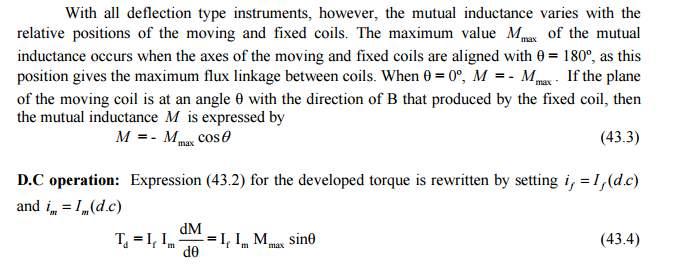
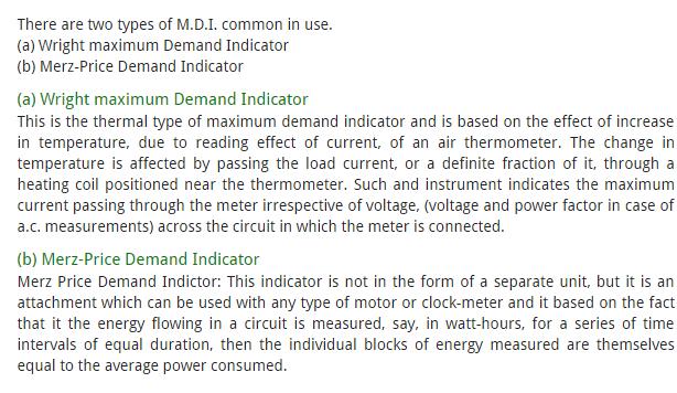
20 MAXIMUM DEMAND INDICATORS Merz price maximum demand indicator indicates A) maximum demand B) average maximum demand over a specified period of time C) maximum energy consumption D) minimum prescribed demand MDI instruments are designed in such a way that they record the base load requirement of electrical energy. They can also measure the peak load but are unable to record sudden short circuit or High motor Starting Currents. Its main construction parts are: 1. A Dial connected with moving system 2. A pointer on dial 3. Reset device 4. Fraction device 5. Indicating pin Maximum demand indicator is often available as a built in feature of three phase energy meters, included in a single case. Maximum Demand is calculated by Maximum Demand(KW)= Maximum Energy Recorded(KWh) Time(hours)
21


22 Wright Maximum Demand Indicator
23 INSTRUMENT TRANSFORMERS Instrument transformers are high accuracy class electrical devices used to isolate or transform voltage or current levels. The most common usage of instrument transformers is to operate instruments or metering from high voltage or high current circuits, safely isolating secondary control circuitry from the high voltages or currents. The primary winding of the transformer is connected to the high voltage or high current circuit, and the meter or relay is connected to the secondary circuit. How will you measure AC currents and voltages of very high magnitude? You will need the measuring instruments having higher range, which literally mean huge instruments. Or there's another way, using the transformation property of AC currents and voltages. You can transform the voltage or current down with a transformer whose turns ratio is accurately known, then measuring the stepped down magnitude with a normal range instrument. The original magnitude can be determined by just multiplying the result with the transformation ratio. Such specially constructed transformers with accurate turns ratio are called as Instrument transformers. These instruments transformers are of two types - (i) Current Transformers (CT) and (ii) Potential Transformers (PT). Current Transformers (CT) Current transformers are generally used to measure currents of high magnitude.
. The secondary winding has large number turns accurately wound for a specific turns ratio.")
24 These transformers step down the current to be measured, so that it can be measured with a normal range ammeter. A Current transformer has only one or very few number of primary turns. The primary winding may be just a conductor or a bus bar placed in a hollow core (as shown in the figure). The secondary winding has large number turns accurately wound for a specific turns ratio. Thus the current transformer steps up (increases) the voltage while stepping down (lowering) the current. Now, the secondary current is measured with the help of an AC ammeter. The turns ratio of a transformer is NP / NS = IS / IP One of the common application of a current transformer is in a 'Digital Clamp Meter'. Generally, current transformers are expressed in their primary to secondary current ratio. A 100:5 CT would mean the secondary current of 5 amperes when primary current is 100 amperes. The secondary current rating is generally 5 amperes or 1 ampere, which is compatible with standard measuring instruments. Potential Transformer (PT) Potential transformers are also known as voltage transformers and they are basically step down transformers with extremely accurate turns ratio. Potential transformers step down the voltage of high magnitude to a lower voltage which can be measured with standard measuring instrument. These transformers have large number of primary
25 turns and smaller number of secondary turns. A potential transformer is typically expressed in primary to secondary voltage ratio. For example, a 600:120 PT would mean the voltage across secondary is 120 volts when primary voltage is 600 volts. The three main tasks of instrument transformers are: 1. To transform currents or voltages from a usually high value to a value easy to handle for relays and instruments. 2. To insulate the metering circuit from the primary high voltage system. 3. To provide possibilities of standardizing the instruments and relays to a few rated currents and voltages. Instrument transformers are special types of transformers intended to measure currents and voltages. The common laws for transformers are valid.
UNIT II MEASUREMENT OF POWER AND ENERGY PART-A
 UNIT II MEASUREMENT OF POWER AND ENERGY PART-A 1. A 3 500 V motor load has a pf of 0.4. Two wattmeters connected to measure the input. They show the input to be 30 kw. Find the reading of each instrument
Synchronous Machines Study Material
 Synchronous machines: The machines generating alternating emf from the mechanical input are called alternators or synchronous generators. They are also known as AC generators. All modern power stations
SAMPLE OF THE STUDY MATERIAL PART OF CHAPTER 2 Measurements of Basic Electrical Quantities 1 (Current Voltage, Resistance)
") SAMPLE OF THE STUDY MATERIAL PART OF CHAPTER 2 Measurements of Basic Electrical Quantities 1 (Current Voltage, Resistance) 2.1 Indicating Instruments Analog Instruments: An analog device is one in which
SAMPLE OF THE STUDY MATERIAL PART OF CHAPTER 2 Measurements of Basic Electrical Quantities 1 (Current Voltage, Resistance) 2.1 Indicating Instruments Analog Instruments: An analog device is one in which
3. What is hysteresis loss? Also mention a method to minimize the loss. (N-11, N-12)
") DHANALAKSHMI COLLEGE OF ENGINEERING, CHENNAI DEPARTMENT OF ELECTRICAL AND ELECTRONICS ENGINEERING EE 6401 ELECTRICAL MACHINES I UNIT I : MAGNETIC CIRCUITS AND MAGNETIC MATERIALS Part A (2 Marks) 1. List
DHANALAKSHMI COLLEGE OF ENGINEERING, CHENNAI DEPARTMENT OF ELECTRICAL AND ELECTRONICS ENGINEERING EE 6401 ELECTRICAL MACHINES I UNIT I : MAGNETIC CIRCUITS AND MAGNETIC MATERIALS Part A (2 Marks) 1. List
Sine waves by far the most important form of alternating quantity important properties are shown below
 AC DC METERS 1 Sine waves by far the most important form of alternating quantity important properties are shown below 2 Average value of a sine wave average value over one (or more) cycles is clearly zero
UNIVERSITY OF TECHNOLOGY By: Fadhil A. Hasan ELECTRICAL MACHINES
 UNIVERSITY OF TECHNOLOGY DEPARTMENT OF ELECTRICAL ENGINEERING Year: Second 2016-2017 By: Fadhil A. Hasan ELECTRICAL MACHINES І Module-II: AC Transformers o Single phase transformers o Three-phase transformers
DIPLOMA IN ELECTRICAL ENGINEERING (DELVI) Term-End Examination December, 2014
 Term-End Examination December, 2014") No. of Printed Pages : 6 BIEE-039 DIPLOMA IN ELECTRICAL ENGINEERING (DELVI) Term-End Examination December, 2014 BIEE-039 : ELECTRICAL MEASUREMENTS AND INSTRUMENTS Time : 2 hours Maximum Marks : 70 Note
No. of Printed Pages : 6 BIEE-039 DIPLOMA IN ELECTRICAL ENGINEERING (DELVI) Term-End Examination December, 2014 BIEE-039 : ELECTRICAL MEASUREMENTS AND INSTRUMENTS Time : 2 hours Maximum Marks : 70 Note
VARIABLE INDUCTANCE TRANSDUCER
 VARIABLE INDUCTANCE TRANSDUCER These are based on a change in the magnetic characteristic of an electrical circuit in response to a measurand which may be displacement, velocity, acceleration, etc. 1.
SECTION 3 BASIC AUTOMATIC CONTROLS UNIT 12 BASIC ELECTRICITY AND MAGNETISM. Unit Objectives. Unit Objectives 2/29/2012
 SECTION 3 BASIC AUTOMATIC CONTROLS UNIT 12 BASIC ELECTRICITY AND MAGNETISM Unit Objectives Describe the structure of an atom. Identify atoms with a positive charge and atoms with a negative charge. Explain
Module 1. Introduction. Version 2 EE IIT, Kharagpur
 Module 1 Introduction Lesson 1 Introducing the Course on Basic Electrical Contents 1 Introducing the course (Lesson-1) 4 Introduction... 4 Module-1 Introduction... 4 Module-2 D.C. circuits.. 4 Module-3
MAHARASHTRA STATE BOARD OF TECHNICAL EDUCATION
 Subject Code: 17322 (EEM) Model Answers Page No: 1 of 16 Important Instructions to examiners: 1) The answers should be examined by key words and not as word-to-word as given in the model answer scheme.
Code No: RR Set No. 1
 Code No: RR310202 Set No. 1 III B.Tech I Semester Regular Examinations, November 2006 ELECTRICAL MEASUREMENTS (Electrical & Electronic Engineering) Time: 3 hours Max Marks: 80 Answer any FIVE Questions
Measurement of Resistance and Potentiometers
 Electrical Measurements International Program Department of Electrical Engineering UNIVERSITAS INDONESIA Measurement of Resistance and Potentiometers Jahroo Renardi Lecturer : Ir. Chairul Hudaya, ST, M.Eng.,
Aligarh College of Engineering & Technology (College Code: 109) Affiliated to UPTU, Approved by AICTE Electrical Engg.
 Affiliated to UPTU, Approved by AICTE Electrical Engg.") Aligarh College of Engineering & Technology (College Code: 19) Electrical Engg. (EE-11/21) Unit-I DC Network Theory 1. Distinguish the following terms: (a) Active and passive elements (b) Linearity and
Aligarh College of Engineering & Technology (College Code: 19) Electrical Engg. (EE-11/21) Unit-I DC Network Theory 1. Distinguish the following terms: (a) Active and passive elements (b) Linearity and
Electrical Machines (EE-343) For TE (ELECTRICAL)
 For TE (ELECTRICAL)") PRACTICALWORKBOOK Electrical Machines (EE-343) For TE (ELECTRICAL) Name: Roll Number: Year: Batch: Section: Semester: Department: N.E.D University of Engineering &Technology, Karachi Electrical Machines
PRACTICALWORKBOOK Electrical Machines (EE-343) For TE (ELECTRICAL) Name: Roll Number: Year: Batch: Section: Semester: Department: N.E.D University of Engineering &Technology, Karachi Electrical Machines
Back to the Basics Current Transformer (CT) Testing
 Testing") Back to the Basics Current Transformer (CT) Testing As test equipment becomes more sophisticated with better features and accuracy, we risk turning our field personnel into test set operators instead of
Back to the Basics Current Transformer (CT) Testing As test equipment becomes more sophisticated with better features and accuracy, we risk turning our field personnel into test set operators instead of
VALLIAMMAI ENGINEERING COLLEGE
 VALLIAMMAI ENGINEERING COLLEGE SRM Nagar, Kattankulathur 603 203 DEPARTMENT OF ELECTRONICS AND INSTRUMENTATION ENGINEERING QUESTION BANK IV SEMESTER EI6402 ELECTRICAL MACHINES Regulation 2013 Academic
Walchand Institute of Technology. Basic Electrical and Electronics Engineering. Transformer
 Walchand Institute of Technology Basic Electrical and Electronics Engineering Transformer 1. What is transformer? explain working principle of transformer. Electrical power transformer is a static device
 EI6301 - ELECTRICAL MEASUREMENTS UNIT I MEASUREMENT OF VOLTAGE AND CURRENT PART-A 1. A PMMC instrument has a 0.12T magnetic flux density in its air gaps. The coil dimensions are D = 1.5 cm and l =2.25
1. Explain in detail the constructional details and working of DC motor.
 DHANALAKSHMI SRINIVASAN INSTITUTE OF RESEARCH AND TECHNOLOGY, PERAMBALUR DEPT OF ECE EC6352-ELECTRICAL ENGINEERING AND INSTRUMENTATION UNIT 1 PART B 1. Explain in detail the constructional details and
Transformers. gpmacademics.weebly.com
 TRANSFORMERS Syllabus: Principles of operation, Constructional Details, Losses and efficiency, Regulation of Transformer, Testing: OC & SC test. TRANSFORMER: It is a static device which transfers electric
5. Transducers Definition and General Concept of Transducer Classification of Transducers
 5.1. Definition and General Concept of Definition The transducer is a device which converts one form of energy into another form. Examples: Mechanical transducer and Electrical transducer Electrical A
Bhoj Reddy Engineering College for Women, Hyderabad Department of Electronics and Communication Engineering Electrical and Electronics Instrumentation
 Bhoj Reddy Engineering College for Women, Hyderabad Department of Electronics and Communication Engineering Electrical and Electronics Instrumentation Academic Year: 2016-17 III B Tech II Semester Branch:
Experiment 45. Three-Phase Circuits. G 1. a. Using your Power Supply and AC Voltmeter connect the circuit shown OBJECTIVE
 Experiment 45 Three-Phase Circuits OBJECTIVE To study the relationship between voltage and current in three-phase circuits. To learn how to make delta and wye connections. To calculate the power in three-phase
3.0 CHARACTERISTICS. Type CKO Overcurrent Relay. switch, which allows the operation indicator target to drop.
 41-101.3A Type CKO Overcurrent Relay switch, which allows the operation indicator target to drop. The front spring, in addition to holding the target, provides restraint for the armature and thus controls
Inductance in DC Circuits
 Inductance in DC Circuits Anurag Srivastava Concept: Inductance is characterized by the behavior of a coil of wire in resisting any change of electric current through the coil. Arising from Faraday's law,
EEE3441 Electrical Machines Department of Electrical Engineering. Lecture. Basic Operating Principles of Transformers
 Department of Electrical Engineering Lecture Basic Operating Principles of Transformers In this Lecture Basic operating principles of following transformers are introduced Single-phase Transformers Three-phase
Electronic Measurements & Instrumentation. 1. Draw the Maxwell s Bridge Circuit and derives the expression for the unknown element at balance?
 UNIT -6 1. Draw the Maxwell s Bridge Circuit and derives the expression for the unknown element at balance? Ans: Maxwell's bridge, shown in Fig. 1.1, measures an unknown inductance in of standard arm offers
Placement Paper For Electrical
 Placement Paper For Electrical Q.1 The two windings of a transformer is (A) conductively linked. (B) inductively linked. (C) not linked at all. (D) electrically linked. Ans : B Q.2 A salient pole synchronous
REQUIRED SKILLS AND KNOWLEDGE UEENEEG101A. Electromagnetic devices and circuits. Topic and Description NIDA Lesson CARD # Magnetism encompassing:
 REQUIRED SKILLS AND KNOWLEDGE UEENEEG101A KS01-EG101A Electromagnetic devices and circuits T1 Magnetism encompassing: Topic and Description NIDA Lesson CARD # magnetic field pattern of bar and horse-shoe
CHAPTER 2. Transformers. Dr Gamal Sowilam
 CHAPTER Transformers Dr Gamal Sowilam Introduction A transformer is a static machine. It is not an energy conversion device, it is indispensable in many energy conversion systems. A transformer essentially
ELECTROMAGNETIC INDUCTION AND ALTERNATING CURRENT (Assignment)
") ELECTROMAGNETIC INDUCTION AND ALTERNATING CURRENT (Assignment) 1. In an A.C. circuit A ; the current leads the voltage by 30 0 and in circuit B, the current lags behind the voltage by 30 0. What is the
ELECTROMAGNETIC INDUCTION AND ALTERNATING CURRENT (Assignment) 1. In an A.C. circuit A ; the current leads the voltage by 30 0 and in circuit B, the current lags behind the voltage by 30 0. What is the
ELECTRICAL MEASUREMENTS
 R10 Set No: 1 1. a) Derive the expression for torque equation for a moving iron attraction type instrument and comment up on the nature of scale [8] b) Define the terms current sensitivity, voltage sensitivity
1 K Hinds 2012 TRANSFORMERS
 1 K Hinds 2012 TRANSFORMERS A transformer changes electrical energy of a given voltage into electrical energy at a different voltage level. It consists of two coils which are not electrically connected,
Transformers. Dr. Gamal Sowilam
 Transformers Dr. Gamal Sowilam OBJECTIVES Become familiar with the flux linkages that exist between the coils of a transformer and how the voltages across the primary and secondary are established. Understand
Three-Phase Induction Motors. By Sintayehu Challa ECEg332:-Electrical Machine I
 Three-Phase Induction Motors 1 2 3 Classification of AC Machines 1. According to the type of current Single Phase and Three phase 2. According to Speed Constant Speed, Variable Speed and Adjustable Speed
Transformer & Induction M/C
 UNIT- 2 SINGLE-PHASE TRANSFORMERS 1. Draw equivalent circuit of a single phase transformer referring the primary side quantities to secondary and explain? (July/Aug - 2012) (Dec 2012) (June/July 2014)
 VIDYARTHIPLUS - ANNA UNIVERSITY ONLINE STUDENTS COMMUNITY UNIT 1 DC MACHINES PART A 1. State Faraday s law of Electro magnetic induction and Lenz law. 2. Mention the following functions in DC Machine (i)
SHRI RAMSWAROOP MEMORIAL COLLEGE OF ENGG. & MANAGEMENT
 SHRI RAMSWAROOP MEMORIAL COLLEGE OF ENGG. & MANAGEMENT B.Tech. [SEM I (CE,EC,EE,EN)] QUIZ TEST-3 (Session: 2012-13) Time: 1 Hour ELECTRICAL ENGINEERING Max. Marks: 30 (EEE-101) Roll No. Academic/26 Refer/WI/ACAD/18
3.1.Introduction. Synchronous Machines
 3.1.Introduction Synchronous Machines A synchronous machine is an ac rotating machine whose speed under steady state condition is proportional to the frequency of the current in its armature. The magnetic
Manuals. Basic Electrical Engineering BE-104
 Manuals Basic Electrical Engineering BE-104 S.NO. EXPERIMENT NAME DATE 1 Measurement of power & power factor in a single phase AC circuit using three Ammeter Method 2 Measurement of active & reactive power
Generator Advanced Concepts
 Generator Advanced Concepts Common Topics, The Practical Side Machine Output Voltage Equation Pitch Harmonics Circulating Currents when Paralleling Reactances and Time Constants Three Generator Curves
Inductance, capacitance and resistance
 Inductance, capacitance and resistance As previously discussed inductors and capacitors create loads on a circuit. This is called reactance. It varies depending on current and frequency. At no frequency,
TRANSFORMERS INTRODUCTION
 Tyco Electronics Corporation Crompton Instruments 1610 Cobb International Parkway, Unit #4 Kennesaw, GA 30152 Tel. 770-425-8903 Fax. 770-423-7194 TRANSFORMERS INTRODUCTION A transformer is a device that
Introduction : Design detailed: DC Machines Calculation of Armature main Dimensions and flux for pole. Design of Armature Winding & Core.
 Introduction : Design detailed: DC Machines Calculation of Armature main Dimensions and flux for pole. Design of Armature Winding & Core. Design of Shunt Field & Series Field Windings. Design detailed:
CHAPTER 2 D-Q AXES FLUX MEASUREMENT IN SYNCHRONOUS MACHINES
 22 CHAPTER 2 D-Q AXES FLUX MEASUREMENT IN SYNCHRONOUS MACHINES 2.1 INTRODUCTION For the accurate analysis of synchronous machines using the two axis frame models, the d-axis and q-axis magnetic characteristics
PHYS 1442 Section 004 Lecture #15
 PHYS 1442 Section 004 Lecture #15 Monday March 17, 2014 Dr. Andrew Brandt Chapter 21 Generator Transformer Inductance 3/17/2014 1 PHYS 1442-004, Dr. Andrew Brandt Announcements HW8 on Ch 21-22 will be
SIDDHARTH GROUP OF INSTITUTIONS :: PUTTUR (AUTONOMOUS) Siddharth Nagar, Narayanavanam Road QUESTION BANK (DESCRIPTIVE)
 Siddharth Nagar, Narayanavanam Road QUESTION BANK (DESCRIPTIVE)") SIDDHARTH GROUP OF INSTITUTIONS :: PUTTUR (AUTONOMOUS) Siddharth Nagar, Narayanavanam Road 517583 QUESTION BANK (DESCRIPTIVE) Suject : Electrical & Electronic Measurements(16EE224) Year & Sem: III-B.Tech
SIDDHARTH GROUP OF INSTITUTIONS :: PUTTUR (AUTONOMOUS) Siddharth Nagar, Narayanavanam Road 517583 QUESTION BANK (DESCRIPTIVE) Suject : Electrical & Electronic Measurements(16EE224) Year & Sem: III-B.Tech
Lecture 36 Measurements of High Voltages (cont) (Refer Slide Time: 00:14)
 (Refer Slide Time: 00:14)") Advances in UHV Transmission and Distribution Prof. B Subba Reddy Department of High Voltage Engg (Electrical Engineering) Indian Institute of Science, Bangalore Lecture 36 Measurements of High Voltages
Advances in UHV Transmission and Distribution Prof. B Subba Reddy Department of High Voltage Engg (Electrical Engineering) Indian Institute of Science, Bangalore Lecture 36 Measurements of High Voltages
Table of Contents. Introduction...2 Conductors and Insulators...3 Current, Voltage, and Resistance...6
 Table of Contents Introduction...2 Conductors and Insulators...3 Current, Voltage, and Resistance...6 Ohm s Law... 11 DC Circuits... 13 Magnetism...20 Alternating Current...23 Inductance and Capacitance...30
Unit 3 Magnetism...21 Introduction The Natural Magnet Magnetic Polarities Magnetic Compass...21
 Chapter 1 Electrical Fundamentals Unit 1 Matter...3 Introduction...3 1.1 Matter...3 1.2 Atomic Theory...3 1.3 Law of Electrical Charges...4 1.4 Law of Atomic Charges...4 Negative Atomic Charge...4 Positive
Introduction. Inductors in AC Circuits.
 Module 3 AC Theory What you ll learn in Module 3. Section 3.1 Electromagnetic Induction. Magnetic Fields around Conductors. The Solenoid. Section 3.2 Inductance & Back e.m.f. The Unit of Inductance. Factors
Half-wave Rectifier AC Meters
 Note-4 1 Half-wave Rectifier AC Meters Disadvantages: 1. In negative half-cycle, reverse current flows through the circuit reduces average value of current meter reads lower than actual. 2. High peak inverse
Preface...x Chapter 1 Electrical Fundamentals
 Preface...x Chapter 1 Electrical Fundamentals Unit 1 Matter...3 Introduction...3 1.1 Matter...3 1.2 Atomic Theory...3 1.3 Law of Electrical Charges...4 1.4 Law of Atomic Charges...5 Negative Atomic Charge...5
Power systems Protection course
 Al-Balqa Applied University Power systems Protection course Department of Electrical Energy Engineering 1 Part 5 Relays 2 3 Relay Is a device which receive a signal from the power system thought CT and
CHAPTER 8: ELECTROMAGNETISM
 CHAPTER 8: ELECTROMAGNETISM 8.1: MAGNETIC EFFECT OF A CURRENT-CARRYING CONDUCTOR Electromagnets 1. Conductor is a material that can flow.. 2. Electromagnetism is the study of the relationship between.and..
CHAPTER 4. Distribution Transformers
 CHAPTER 4 Distribution Transformers Introduction A transformer is an electrical device that transfers energy from one circuit to another purely by magnetic coupling. Relative motion of the parts of the
1. If the flux associated with a coil varies at the rate of 1 weber/min,the induced emf is
 1. f the flux associated with a coil varies at the rate of 1 weber/min,the induced emf is 1 1. 1V 2. V 60 3. 60V 4. Zero 2. Lenz s law is the consequence of the law of conservation of 1. Charge 2. Mass
Reg. No. : BASIC ELECTRICAL TECHNOLOGY (ELE 101)
") Department of Electrical and Electronics Engineering Reg. No. : MNIPL INSTITUTE OF TECHNOLOGY, MNIPL ( Constituent Institute of Manipal University, Manipal) FIRST SEMESTER B.E. DEGREE MKEUP EXMINTION (REVISED
Department of Electrical and Electronics Engineering Reg. No. : MNIPL INSTITUTE OF TECHNOLOGY, MNIPL ( Constituent Institute of Manipal University, Manipal) FIRST SEMESTER B.E. DEGREE MKEUP EXMINTION (REVISED
WELCOME TO THE LECTURE
 WLCOM TO TH LCTUR ON TRNFORMR Single Phase Transformer Three Phase Transformer Transformer transformer is a stationary electric machine which transfers electrical energy (power) from one voltage level
Electrical Theory. Power Principles and Phase Angle. PJM State & Member Training Dept. PJM /22/2018
 Electrical Theory Power Principles and Phase Angle PJM State & Member Training Dept. PJM 2018 Objectives At the end of this presentation the learner will be able to: Identify the characteristics of Sine
PRINCIPLES OF MEASUREMENT AND INSTRUMENTATION & INSTRUMENTS
 Contents i SYLLABUS osmania university UNIT - I PRINCIPLES OF MEASUREMENT AND INSTRUMENTATION & INSTRUMENTS Principles of Measurement and Instrumentation and Instruments : Objectives of Measurements, Analog
POWER SYSTEM II LAB MANUAL
 POWER SYSTEM II LAB MANUAL (CODE : EE 692) JIS COLLEGE OF ENGINEERING (An Autonomous Institution) Electrical Engineering Department Kalyani, Nadia POWER SYSTEM II CODE : EE 692 Contacts :3P Credits : 2
MAHARASHTRA STATE BOARD OF TECHNICAL EDUCATION
 Important Instructions to examiners: 1) The answers should be examined by key words and not as word-to-word as given in the model answer scheme. 2) The model answer and the answer written by candidate
INSTITUTE OF AERONAUTICAL ENGINEERING (AUTONOMOUS)
") Name Code Class Branch INSTITUTE OF AERONAUTICAL ENGINEERING (AUTONOMOUS) Dundigal, Hyderabad -500 043 CIVIL ENGINEERING TUTORIAL QUESTION BANK : ELECTRICAL AND ELECTRONICS ENGINEERING : A30203 : II B.
Name Code Class Branch INSTITUTE OF AERONAUTICAL ENGINEERING (AUTONOMOUS) Dundigal, Hyderabad -500 043 CIVIL ENGINEERING TUTORIAL QUESTION BANK : ELECTRICAL AND ELECTRONICS ENGINEERING : A30203 : II B.
End-of-Chapter Exercises
 End-of-Chapter Exercises Exercises 1 12 are primarily conceptual questions designed to see whether you understand the main concepts of the chapter. 1. The four areas in Figure 20.34 are in a magnetic field.
AC metrology. Resources and methods for learning about these subjects (list a few here, in preparation for your research):
:") AC metrology This worksheet and all related files are licensed under the Creative Commons Attribution License, version 1.0. To view a copy of this license, visit http://creativecommons.org/licenses/by/1.0/,
AC metrology This worksheet and all related files are licensed under the Creative Commons Attribution License, version 1.0. To view a copy of this license, visit http://creativecommons.org/licenses/by/1.0/,
SYNCHRONOUS MACHINES
 SYNCHRONOUS MACHINES The geometry of a synchronous machine is quite similar to that of the induction machine. The stator core and windings of a three-phase synchronous machine are practically identical
ENGINEERING ACADEMY X V
 1. Two incandescent bulbs of rating 230, 100 W and 230, 500 W are connected in parallel across the mains. As a result, what will happen? a) 100 W bulb will glow brighter b) 500 W bulb will glow brighter
APPLICATION NOTE - 018
 APPLICATION NOTE - 018 Power Transformers Background Power Transformers are used within an AC power distribution systems to increase or decrease the operating voltage to achieve the optimum transmission
MAHARASHTRA STATE BOARD OF TECHNICAL EDUCATION
 Important Instructions to examiners: 1) The answers should be examined by key words and not as word-to-word as given in the model answer scheme. 2) The model answer and the answer written by candidate
Methods of secondary short circuit current control in single phase transformers
 2015; 1(8): 412-417 ISSN Print: 2394-7500 ISSN Online: 2394-5869 Impact Factor: 5.2 IJAR 2015; 1(8): 412-417 www.allresearchjournal.com Received: 17-05-2015 Accepted: 20-06-2015 Parantap Nandi A/2, Building
UNIT 1 CIRCUIT ANALYSIS 1 What is a graph of a network? When all the elements in a network is replaced by lines with circles or dots at both ends.
 UNIT 1 CIRCUIT ANALYSIS 1 What is a graph of a network? When all the elements in a network is replaced by lines with circles or dots at both ends. 2 What is tree of a network? It is an interconnected open
EE Chapter 7 Measuring Instruments
 EE 2145230 Chapter 7 Measuring Instruments 7.1 Meter Movements The basic principle of many electric instruments is that of the galvanometer. This is a device which reacts to minute electromagnetic influences
TRANSFORMER THEORY. Mutual Induction
 Transformers Transformers are used extensively for AC power transmissions and for various control and indication circuits. Knowledge of the basic theory of how these components operate is necessary to
Chapter Moving Charges and Magnetism
 100 Chapter Moving Charges and Magnetism 1. The power factor of an AC circuit having resistance (R) and inductance (L) connected in series and an angular velocity ω is [2013] 2. [2002] zero RvB vbl/r vbl
HIGH VOLTAGE ENGINEERING(FEEE6402) LECTURER-24
 LECTURER-24") LECTURER-24 GENERATION OF HIGH ALTERNATING VOLTAGES When test voltage requirements are less than about 300kV, a single transformer can be used for test purposes. The impedance of the transformer should
LECTURER-24 GENERATION OF HIGH ALTERNATING VOLTAGES When test voltage requirements are less than about 300kV, a single transformer can be used for test purposes. The impedance of the transformer should
Solution for Electrical and Electronic Measurements
 Q.1) Solution for Electrical and Electronic Measurements May 2016 Index a). 2 b). 2 c). 3-4 d). 5-6 e).. 6 Q.2) a). 7-11 b). 11-16 Q.3) a). 17-20 b). 21-22 Q.4) a). 23-25 b). 25-27 Q.5) a). N.A b). 28-31
Reyrolle Protection Devices. 7PG11-18 Alpha Electromechanical Relays. Siemens. Answers for energy.
 Reyrolle Protection Devices 7PG11-18 Alpha Electromechanical Relays Answers for energy. Siemens Alpha Technical Manual Contents Contents Technical Manual Chapters 1. Introduction to Electromechanical
ELECTROMAGNETIC INDUCTION
 NAME SCHOOL INDEX NUMBER DATE ELECTROMAGNETIC INDUCTION 1. 1995 Q5 P2 (a) (i) State the law of electromagnetic induction ( 2 marks) (ii) Describe an experiment to demonstrate Faraday s law (4 marks) (b)
MAHARASHTRA STATE BOARD OF TECHNICAL EDUCATION
 Important Instructions to examiners: 1) The answers should be examined by key words and not as word-to-word as given in the model answer scheme. 2) The model answer and the answer written by candidate
CHAPTER 5 SYNCHRONOUS GENERATORS
 CHAPTER 5 SYNCHRONOUS GENERATORS Summary: 1. Synchronous Generator Construction 2. The Speed of Rotation of a Synchronous Generator 3. The Internal Generated Voltage of a Synchronous Generator 4. The Equivalent
EE401,EC401,DEE19,DETE19
 EE401,EC401,DEE19,DETE19 IV SEMESTER DIPLOMA EXAMINATION, JANUARY 2013 LINEAR & DIGITAL ICs Time: 3 Hours Max. Marks: 75 GROUP A : Answer any three questions. (Question No. 1 is compulsory) Q.1 What is
MCQ Questions. Elements of Electrical Engineering (EEE)
") MCQ Questions 1. The length of conductor is doubled and its area of cross section is also doubled, then the resistance will. a. Increase four time b. Remain unchanged c. Decrease to four times d. Change
MCQ Questions 1. The length of conductor is doubled and its area of cross section is also doubled, then the resistance will. a. Increase four time b. Remain unchanged c. Decrease to four times d. Change
1. A battery has an emf of 12.9 volts and supplies a current of 3.5 A. What is the resistance of the circuit?
 1. A battery has an emf of 12.9 volts and supplies a current of 3.5 A. What is the resistance of the circuit? (a) 3.5 Ω (b) 16.4 Ω (c) 3.69 Ω (d) 45.15 Ω 2. Sign convention used for potential is: (a) Rise
Power. Power is the rate of using energy in joules per second 1 joule per second Is 1 Watt
 3 phase Power All we need electricity for is as a source of transport for energy. We can connect to a battery, which is a source of stored energy. Or we can plug into and electric socket at home or in
MAHARASHTRA STATE BOARD OF TECHNICAL EDUCATION
 Important Instructions to examiners: 1. The answers should be examined by key words and not as word-to-word as given in the model answer scheme. 2. The model answer and the answer written by candidate
Review 6. unlike poles cause the magnets to attract. like poles cause the magnets to repel.
 Review 6 1. The two characteristics of all magnets are: they attract and hold Iron, and, if free to move, they will assume roughly a south - north position. 2. Lines of flux always leave the north pole
Engineering Science OUTCOME 4 - TUTORIAL 3 CONTENTS. 1. Transformers
 Unit : Unit code: QCF Level: 4 Credit value: 5 SYLLABUS Engineering Science L/60/404 OUTCOME 4 - TUTOIAL 3 Be able to apply single phase AC theory to solve electrical and electronic engineering problems
Type CVX and CVX-1 Synchro-Verifier Relays
 I.L. 41-682.11 Type CVX and CVX-1 Synchro-Verifier Relays TIME DIAL POTENTIOMETER (R3) CIRCLE ADJUST RESTRAINT ELECTROMAGNET Figure 1. CVX-1 Relay Front View, Out of Case OPERATING ELECTROMAGNET TELEPHONE
SECTION 4 TRANSFORMERS. Yilu (Ellen) Liu. Associate Professor Electrical Engineering Department Virginia Tech University
 Liu. Associate Professor Electrical Engineering Department Virginia Tech University") SECTION 4 TRANSFORMERS Yilu (Ellen) Liu Associate Professor Electrical Engineering Department Virginia Tech University Analysis of Transformer Turns Ratio......................... 4.2 Analysis of a Step-Up
SECTION 4 TRANSFORMERS Yilu (Ellen) Liu Associate Professor Electrical Engineering Department Virginia Tech University Analysis of Transformer Turns Ratio......................... 4.2 Analysis of a Step-Up
INDEX IEC:
 60050-300 IEC:2001 173 INDEX A absolute absolute error... 311-01-05 (absolute) frequency deviation... 314-08-07 accessory accessory (of a measuring instrument)... 312-03-01 accessory of limited interchangeability...
Relay Types and Applications Dr. Sasidharan Sreedharan
 O&M of Protection System and Relay Coordination Relay Types and Applications Dr. Sasidharan Sreedharan www.sasidharan.webs.com Detailed Schedule 2 SIMPLE RELAY Magnitude Rate of Change Phase Angle Direction
INSTITUTE OF AERONAUTICAL ENGINEERING (AUTONOMOUS) Dundigal, Hyderabad
 Dundigal, Hyderabad") INSTITUTE OF AERONAUTICAL ENGINEERING (AUTONOMOUS) Dundigal, Hyderabad - 500 043 CIVIL ENGINEERING ASSIGNMENT Name : Electrical and Electronics Engineering Code : A30203 Class : II B. Tech I Semester Branch
INSTITUTE OF AERONAUTICAL ENGINEERING (AUTONOMOUS) Dundigal, Hyderabad - 500 043 CIVIL ENGINEERING ASSIGNMENT Name : Electrical and Electronics Engineering Code : A30203 Class : II B. Tech I Semester Branch
Chapter 25. Electromagnetic Induction
 Lecture 28 Chapter 25 Electromagnetic Induction Electromagnetic Induction Voltage is induced (produced) when the magnetic field changes near a stationary conducting loop or the conductor moves through
PHYSICS WORKSHEET CLASS : XII. Topic: Alternating current
 PHYSICS WORKSHEET CLASS : XII Topic: Alternating current 1. What is mean by root mean square value of alternating current? 2. Distinguish between the terms effective value and peak value of an alternating
Electrical Theory 2 Lessons for Fall Semester:
 Electrical Theory 2 Lessons for Fall Semester: Lesson 1 Magnetism Lesson 2 Introduction to AC Theory Lesson 3 Lesson 4 Capacitance and Capacitive Reactance Lesson 5 Impedance and AC Circuits Lesson 6 AC
CERTIFICATES OF COMPETENCY IN THE MERCHANT NAVY MARINE ENGINEER OFFICER
 CERTIFICATES OF COMPETENCY IN THE MERCHANT NAVY MARINE ENGINEER OFFICER EXAMINATIONS ADMINISTERED BY THE SCOTTISH QUALIFICATIONS AUTHORITY ON BEHALF OF THE MARITIME AND COASTGUARD AGENCY STCW 78 as amended
A Practical Guide to Free Energy Devices
 A Practical Guide to Free Energy Devices Part PatD14: Last updated: 25th February 2006 Author: Patrick J. Kelly This patent application shows the details of a device which it is claimed, can produce sufficient
Type of loads Active load torque: - Passive load torque :-
 Type of loads Active load torque: - Active torques continues to act in the same direction irrespective of the direction of the drive. e.g. gravitational force or deformation in elastic bodies. Passive