Inductance, capacitance and resistance
|
|
|
- Barbara Wilkins
- 6 years ago
- Views:
Transcription
1 Inductance, capacitance and resistance As previously discussed inductors and capacitors create loads on a circuit. This is called reactance. It varies depending on current and frequency. At no frequency, or DC there is no reactance. At low frequency capacitors create the most reactance At high frequency inductors create the most reactance
2 Inductance, capacitance and resistance Since inductive reactance varies with frequency and inductance the formula for this is X l =2πfL where f is frequency and L is Henrys and X l is in Ohms. Ohms law for inductance is the same as that used to combine resistances in series and parallel circuits. An inductor will cause current to lag behind voltage because induced voltage resists current changes.
3 Inductance, capacitance and resistance Since capacitive reactance varies with frequency and capacitance the formula for this is X c =1/(2πfC) where f is frequency and C is Farads and X c is in Ohms. Ohms law for capacitance is inverted from that used to combine resistances in series and parallel circuits. A capacitor will cause voltage to lag behind current because at 0 volts charge the circuit will be at maximum current.
4 Inductance, capacitance and resistance Therefore capacitive and inductive reactance counter, or cancel each other. Their effect on phase counters the other s phase effect. ELI the ICEman E leads I with an L (inductor) I leads E with a C (capacitor)
5 Inductance, capacitance and resistance Since resistance doesn t effect phase the net of the two reactances, with the lessor subtracted from the greater, will act upon total impedance at 90 to resistance. But since reactance is already expressed in the form of Ohms in a purely reactive circuit Ohms laws applies normally for a purely inductive or capacitive circuit.
6 Inductance, capacitance and resistance Since both reactance s cause current to lead or lag by 90 they must be added to resistances using the Pythagorean theorem. C 2 = A 2 + B 2 Z t2 = R 2 + X (c-l or l-c) 2 Z t = the circuits total opposition to current flow. If the circuit has no AC, or inductors and capacitors then Z t = R t
7 Inductance, capacitance and resistance Ohms law works for AC circuits with inductors, capacitors and resistances. Series circuits solve for impedance first, in parallel solve for currents since the V-drop is the same across each leg.
8 Inductance, capacitance and resistance Resonance is when the frequency is such that a capacitor in series with an inductor cancel each other s reactance. Similar resonance in a parallel circuit with an inductor and capacitor will have infinite resistance at a resonant frequency.
9 Inductance, capacitance and resistance Power factor is 100% in DC circuits. It is the ratio of apparent power to true power.
10 Inductance, capacitance and resistance Apparent Power is that derived from measuring voltage and current in an AC circuit and multiplying them. True power is the power actually used by the resistive load and does not contain the power lost to reactance. Power factor = 100 X True Power / Apparent Power
11 Inductance, capacitance and resistance 110V 400hz 270 Ω X l = 2πfL X c = 1/(2πfC) R t = R Z 2 = R t2 + (X c -X l ) 2 I t = E/Z 300µf 31mH
12 Inductance, capacitance and resistance 270 Ω X l = 2πfL X c = 1/(2πfC) R t = R I t = E/Z 300µf 110V 400htz 31mH Z = R X l X c /v(x l2 X c2 +(R X l -R X c ) 2 )
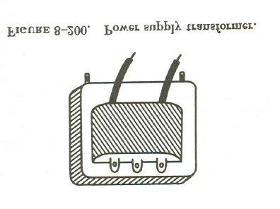
13 Transformers A transformer is a set of two or more inductors in close proximity whose purpose is to exchange voltage for current in an AC circuit. If the voltage or current is incorrect for a given application it can be transformed up or down. The catch is if one goes up, the other must go down. The other catch is this will lose some power within the circuit.
14 Transformers
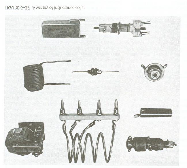
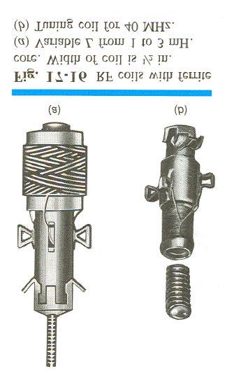
15 Transformers Essentially one inductive coil will have thicker wire with fewer loops or turns than the other. They can be high current or high voltage coils depending on what they need for output.
16 Transformers
17 Transformers
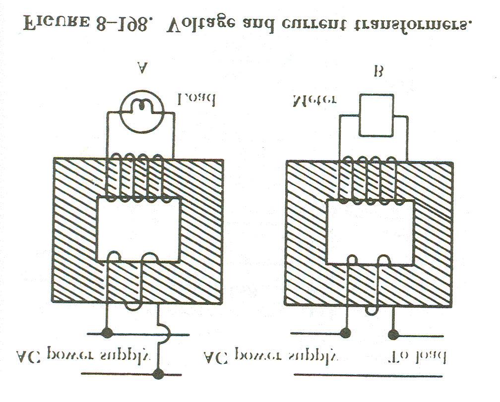
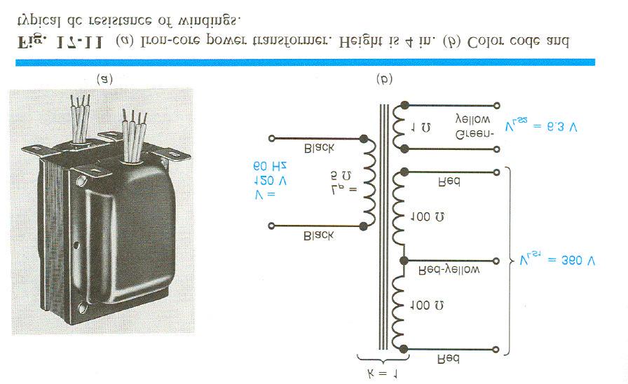
18 Transformers Generally a step up or step down transformer refers to the voltage being stepped. The unit can include a rectifier to convert the output to DC. It can have multiple coils tapped into at various points internally for a series of different outputs from one unit.
19 Transformers
20 Transformers They can be cooled, often in an oil bath. They are limited by the apparent power being driven through them. Excessive power input or output can overheat them. They can have different cores from iron to air.
21 Transformers
22 Transformers They can fully isolate one part of a circuit from another such that electrons do not actually travel through the transformer. or they can be wired such that the circuit is not isolated. They are very efficient, loosing a little power to heat and hysterisis. But they are inductors so will effect the impedance of the AC circuit.
23 Transformers
24 Transformers
25 Transformers
26 Transformers
27 Transformers
28 Transformers
29 Transformers
30 Transformers
31 Transformers Transformers will cause the voltage of an AC circuit to be 180 out of phase between the primary and secondary windings. This is because the current is 90 out of phase with the primary voltage and the secondary voltage is 90 out of phase with that current. Consequently a circuit with multiple transformers must be designed to accommodate phase effect.
32 Transformers
33 Transformers Another neat feature of transformers is that they use almost no power when idling in an AC circuit. In other words when there is no load on the secondary circuit the counter EMF in the primary cancels out almost all current flow in that winding.
34 Transformers They can be single dual or three phase. Each winding will need a reciprocal winding.
35 Transformers
36 Transformers
37 Transformers Their cores will be laminated to reduce eddy current effects. And they can have a core that moves into and out of the coil. This makes it an adjustable transformer which can be used to tune a circuit. Capacitors can also be made variable for the same reason.
38 Transformers
39 Motors are electronic devices. If it operates by internal combustion it is properly called an engine. Like a generator, the relationship of motion, current flow and direction of the magnetic lines of flux will determine what an electric motor will do.
40
41 Since the left hand rule for generators defines current flow based upon motion direction a reverse rule, the right hand rule for motors defines the motion direction based upon current flow. Each respective finger remains the same with the index finger defining the lines of flux from north to south, the thumb defines the motion force, and the middle finger points to the direction of current flow.
42 This is because of the original left hand rule which describes the behavior of flux around a current carrying conductor. In this case the lines of force below the conductor are in the same direction and repel, while the lines above are opposite and attract.
43 Since this force applied will vary depending on the direction the conductor travels, and since the direction varies since the conductor is on a rotating armature it would eventually hit neutral force and then begin to reverse force. So, more than one conductor is used, there is a switching commutator, and the armature has a lot of mass to ensure momentum.
44
45 In some strategies they have more than one brush assembly riding on the commutator. This allows more than one set of conductors to apply torque at the same time, but it will also require a second set of field poles.
46 Motors, like anything, have different phases of operation, and different operating needs to meet each specific application. All will need special attention to start spinning, some make their power through high RPM and low torque, other have a reverse need. Some are also combined with a generator function.
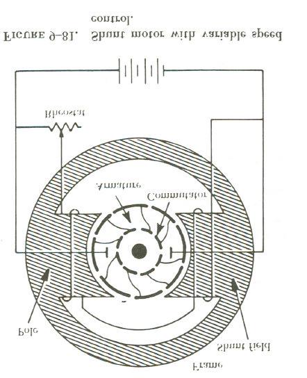
47 Like generators there are permanent magnet and electro magnet motors. Typically permanent mag motors are only used in small unit application. Whereas high load/torque units usually utilize electro magnetic fields. These can also be wired in series or parallel with the armature, or both with a split field.
48 Like generators, motors a have problems with armature reaction. They also generate counter EMF as a result of their motion. This is in fact what limits their maximum speed. As a motor approaches this maximum no load speed it s current flow will reduce to very little.
49 If load is applied, RPM will reduce, current flow will increase attempting to reestablish EMF and counter EMF balance. As load is increased, RPM is decreased, and current is increased.
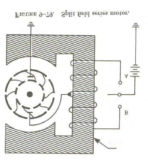
50 In a series wound motor all the current travels through both the field and armature. This allows for a very high torque at low speeds. This is a good design for high load low speed such as a starter motor. But these don t limit well and will go to very high speed if not loaded. Field windings are heavy with fewer turns.
51
52
53
54 In a parallel, or shunt would motor the field is wound with finer wire since there is no armature in line to provide resistance. Consequently these motors don t start well, but are fairly stable in cruise RPM. These units are often known as constant speed motors, although they do vary RPM slightly due to changes in load.
55
56 But, they will need some strategy to get started. One is to unload them during start, another is to include a small series field to assist starting, or they may have alternative starting strategies if they are an AC motor.
57
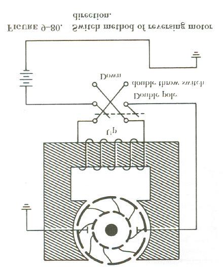
58 DC motors are easily reversible. Just switch the lead polarity of either the field or the armature. Switching the polarity of both will net the same direction of rotation due to the right hand rule.
59
60 This is very easy in a permanent magnet motor. One way would be to have two opposite would fields in the motor, picking one for each direction. This is common for things like landing gear or flap motors.
61
62 Brush, commutator and bearing maintenance is the same as that of a generator. Brush arcing may be more of a problem in motors with a high variability of load. Brush phase is critical to RPM and load due to armature reaction.
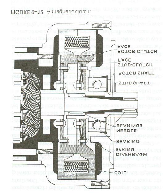
63 Some units incorporate the use of magnetic brakes and clutches. This allows for a greater control during either starting or stopping the unit. Can be used to prevent undue binding on the mechanical linkage connected to the motor or may disengage the motor when not needed as in the case of the bendix drive used in starter motors. They may also incorporate speed or thermal limiting devices.
64
65
66 Many motors are duty limited. They can produce more heat then they can reject during a given period of operation. Starter motors, and landing gear motors my be an example of this.
67 Not all motors are designed to output rotating motion. Some put out linear motion. The simplest of these is the solenoid which is a coil around a movable core. A spring moves the core one way, and the energized field moves it the other way.
68 Another type does spin, but this spinning drives an internal worm gear which then gives high torque linear motion. This is also a torque increasing gear reduction system which is often used in both linear and rotary motors.
69 Although the previous discussion pertains to both DC and AC motors, the two are very different. The AC motor comes in tow main categories: the induction motor, and the synchronous motor. These can be single, two, or three phase motors. (one could go with more phases but the added complexity would not derive much benefit)
70
71 In general the advantage of AC is that one can get more power for less weight. The down side is batteries don t do AC without help. They also don t self start as well as DC units with equal torque load. A third type, the universal motor, works on both AC and DC, but these are not efficient, particularly at 400hz
72 In essence the induction motor self induces current in the armature, there are no brushes. This is done by winding the fields with each phase of the AC generator in a staggered manner much like the generator is wound. This causes each respective field generated by the phase current to increase and decrease in a manner that emulates a flow around the field perimeter.
73
74 This is similar to a row of lights with each bulb sequentially turned on so that it looks like the light moves along the path of bulbs. In truth, there is no flow, each bulb simply turns on and off in phase.
75
76 The rotor in this motor is a can shape with copper bars running the length connected together at the ends via a ring. As the current changes in the surrounding field it induces current in these copper bars. The resultant flux will cause the bars to try to follow the field until it reaches neutral. As such, higher slip causes more torque.
77
78 So, as the load is increased, RPM is decreased causing more slip, causing more rotor current, causing more force to catch up with the field.
79 Self starting for AC motors is a challenge, particularly single phase units. They are often coupled with a tickler winding that is wired in series with a large electrolytic capacitor. The capacitor splits the current phase from the normal one causing those windings to pull more at zero to low RPM. A centrifugal switch cuts out this winding.
80
81 Another strategy is to split the field poles slightly with a magnetically shaded side. This in effect curves the magnetic lines causing them to pull at an angle slightly off from the center of rotation. These units are very low torque starting and have been replaced by the Cap start units.
82 A synchronous motor is one where the AC field is the same as the induction unit, but the armature doesn t self induce. It has DC applied to the rotor so it will stay right in phase with the induction windings since it needs no slip to induce rotor current. Typically uses 3 phase current, with a rectifier to produce the rotor DC.
83 Rotor speed in an AC motor is a function of the AC hz, as well as the current being applied and the load being driven. Like their DC counterparts as the load increases current increases, heat generation increases and melt down will eventually happen.
84 Motors
Table of Contents. Introduction...2 Conductors and Insulators...3 Current, Voltage, and Resistance...6
 Table of Contents Introduction...2 Conductors and Insulators...3 Current, Voltage, and Resistance...6 Ohm s Law... 11 DC Circuits... 13 Magnetism...20 Alternating Current...23 Inductance and Capacitance...30
3. What is hysteresis loss? Also mention a method to minimize the loss. (N-11, N-12)
") DHANALAKSHMI COLLEGE OF ENGINEERING, CHENNAI DEPARTMENT OF ELECTRICAL AND ELECTRONICS ENGINEERING EE 6401 ELECTRICAL MACHINES I UNIT I : MAGNETIC CIRCUITS AND MAGNETIC MATERIALS Part A (2 Marks) 1. List
DHANALAKSHMI COLLEGE OF ENGINEERING, CHENNAI DEPARTMENT OF ELECTRICAL AND ELECTRONICS ENGINEERING EE 6401 ELECTRICAL MACHINES I UNIT I : MAGNETIC CIRCUITS AND MAGNETIC MATERIALS Part A (2 Marks) 1. List
 VIDYARTHIPLUS - ANNA UNIVERSITY ONLINE STUDENTS COMMUNITY UNIT 1 DC MACHINES PART A 1. State Faraday s law of Electro magnetic induction and Lenz law. 2. Mention the following functions in DC Machine (i)
VALLIAMMAI ENGINEERING COLLEGE
 VALLIAMMAI ENGINEERING COLLEGE SRM Nagar, Kattankulathur 603 203 DEPARTMENT OF ELECTRONICS AND INSTRUMENTATION ENGINEERING QUESTION BANK IV SEMESTER EI6402 ELECTRICAL MACHINES Regulation 2013 Academic
An induced emf is the negative of a changing magnetic field. Similarly, a self-induced emf would be found by
 This is a study guide for Exam 4. You are expected to understand and be able to answer mathematical questions on the following topics. Chapter 32 Self-Induction and Induction While a battery creates an
Alternating Current Page 1 30
 Alternating Current 26201 11 Page 1 30 Calculate the peak and effective voltage of current values for AC Calculate the phase relationship between two AC waveforms Describe the voltage and current phase
Placement Paper For Electrical
 Placement Paper For Electrical Q.1 The two windings of a transformer is (A) conductively linked. (B) inductively linked. (C) not linked at all. (D) electrically linked. Ans : B Q.2 A salient pole synchronous
Electrical Theory 2 Lessons for Fall Semester:
 Electrical Theory 2 Lessons for Fall Semester: Lesson 1 Magnetism Lesson 2 Introduction to AC Theory Lesson 3 Lesson 4 Capacitance and Capacitive Reactance Lesson 5 Impedance and AC Circuits Lesson 6 AC
Module 1. Introduction. Version 2 EE IIT, Kharagpur
 Module 1 Introduction Lesson 1 Introducing the Course on Basic Electrical Contents 1 Introducing the course (Lesson-1) 4 Introduction... 4 Module-1 Introduction... 4 Module-2 D.C. circuits.. 4 Module-3
Hours / 100 Marks Seat No.
 17415 15162 3 Hours / 100 Seat No. Instructions (1) All Questions are Compulsory. (2) Answer each next main Question on a new page. (3) Illustrate your answers with neat sketches wherever necessary. (4)
Chapter 11. Alternating Current
 Unit-2 ECE131 BEEE Chapter 11 Alternating Current Objectives After completing this chapter, you will be able to: Describe how an AC voltage is produced with an AC generator (alternator) Define alternation,
Question Paper Profile
 I Scheme Question Paper Profile Program Name : Electrical Engineering Program Group Program Code : EE/EP/EU Semester : Third Course Title : Electrical Circuits Max. Marks : 70 Time: 3 Hrs. Instructions:
ELECTROMAGNETIC INDUCTION AND ALTERNATING CURRENT (Assignment)
") ELECTROMAGNETIC INDUCTION AND ALTERNATING CURRENT (Assignment) 1. In an A.C. circuit A ; the current leads the voltage by 30 0 and in circuit B, the current lags behind the voltage by 30 0. What is the
ELECTROMAGNETIC INDUCTION AND ALTERNATING CURRENT (Assignment) 1. In an A.C. circuit A ; the current leads the voltage by 30 0 and in circuit B, the current lags behind the voltage by 30 0. What is the
Aligarh College of Engineering & Technology (College Code: 109) Affiliated to UPTU, Approved by AICTE Electrical Engg.
 Affiliated to UPTU, Approved by AICTE Electrical Engg.") Aligarh College of Engineering & Technology (College Code: 19) Electrical Engg. (EE-11/21) Unit-I DC Network Theory 1. Distinguish the following terms: (a) Active and passive elements (b) Linearity and
Aligarh College of Engineering & Technology (College Code: 19) Electrical Engg. (EE-11/21) Unit-I DC Network Theory 1. Distinguish the following terms: (a) Active and passive elements (b) Linearity and
INSTITUTE OF AERONAUTICAL ENGINEERING (AUTONOMOUS) Dundigal, Hyderabad
 Dundigal, Hyderabad") INSTITUTE OF AERONAUTICAL ENGINEERING (AUTONOMOUS) Dundigal, Hyderabad - 500 043 CIVIL ENGINEERING ASSIGNMENT Name : Electrical and Electronics Engineering Code : A30203 Class : II B. Tech I Semester Branch
INSTITUTE OF AERONAUTICAL ENGINEERING (AUTONOMOUS) Dundigal, Hyderabad - 500 043 CIVIL ENGINEERING ASSIGNMENT Name : Electrical and Electronics Engineering Code : A30203 Class : II B. Tech I Semester Branch
SECTION 3 BASIC AUTOMATIC CONTROLS UNIT 12 BASIC ELECTRICITY AND MAGNETISM. Unit Objectives. Unit Objectives 2/29/2012
 SECTION 3 BASIC AUTOMATIC CONTROLS UNIT 12 BASIC ELECTRICITY AND MAGNETISM Unit Objectives Describe the structure of an atom. Identify atoms with a positive charge and atoms with a negative charge. Explain
ENGINEERING ACADEMY X V
 1. Two incandescent bulbs of rating 230, 100 W and 230, 500 W are connected in parallel across the mains. As a result, what will happen? a) 100 W bulb will glow brighter b) 500 W bulb will glow brighter
INSTITUTE OF AERONAUTICAL ENGINEERING (AUTONOMOUS)
") Name Code Class Branch INSTITUTE OF AERONAUTICAL ENGINEERING (AUTONOMOUS) Dundigal, Hyderabad -500 043 CIVIL ENGINEERING TUTORIAL QUESTION BANK : ELECTRICAL AND ELECTRONICS ENGINEERING : A30203 : II B.
Name Code Class Branch INSTITUTE OF AERONAUTICAL ENGINEERING (AUTONOMOUS) Dundigal, Hyderabad -500 043 CIVIL ENGINEERING TUTORIAL QUESTION BANK : ELECTRICAL AND ELECTRONICS ENGINEERING : A30203 : II B.
1. (a) Determine the value of Resistance R and current in each branch when the total current taken by the curcuit in figure 1a is 6 Amps.
 Determine the value of Resistance R and current in each branch when the total current taken by the curcuit in figure 1a is 6 Amps.") Code No: 07A3EC01 Set No. 1 II B.Tech I Semester Regular Examinations, November 2008 ELECTRICAL AND ELECTRONICS ENGINEERING ( Common to Civil Engineering, Mechanical Engineering, Mechatronics, Production
Code No: 07A3EC01 Set No. 1 II B.Tech I Semester Regular Examinations, November 2008 ELECTRICAL AND ELECTRONICS ENGINEERING ( Common to Civil Engineering, Mechanical Engineering, Mechatronics, Production
AP Physics C. Alternating Current. Chapter Problems. Sources of Alternating EMF
 AP Physics C Alternating Current Chapter Problems Sources of Alternating EMF 1. A 10 cm diameter loop of wire is oriented perpendicular to a 2.5 T magnetic field. What is the magnetic flux through the
Basics of Electricity
 Basics of Electricity A quickstep Online Course Siemens industry, Inc. www.usa.siemens.com/step Trademarks Siemens is a trademark of Siemens AG. Product names mentioned may be trademarks or registered
Objective Questions UNIT-I TRANSIENT ANALYSIS (First and Second Order Circuits)
") Objective Questions: Objective Questions UNIT-I TRANSIENT ANALYSIS (First and Second Order Circuits) 1. The time constant of RL circuit is... a)rl b)l/r c)r/l d)l 2. Inductor does not allow sudden changes
Objective Questions: Objective Questions UNIT-I TRANSIENT ANALYSIS (First and Second Order Circuits) 1. The time constant of RL circuit is... a)rl b)l/r c)r/l d)l 2. Inductor does not allow sudden changes
Exercises of resistors 1. Calculate the resistance of a 10 m long Copper wire with diameter d = 1.0 mm.
 Exercises of resistors 1. Calculate the resistance of a 10 m long Copper wire with diameter d = 1.0 mm. 2. Calculate the resistances of following equipment: using 220V AC a) a 1000 W electric heater b)
PART A. 1. List the types of DC Motors. Give any difference between them. BTL 1 Remembering
 UNIT I DC MACHINES Three phase circuits, a review. Construction of DC machines Theory of operation of DC generators Characteristics of DC generators Operating principle of DC motors Types of DC motors
INSTITUTE OF AERONAUTICAL ENGINEERING (Autonomous) Dundigal, Hyderabad
 Dundigal, Hyderabad") INSTITUTE OF AERONAUTICAL ENGINEERING (Autonomous) Dundigal, Hyderabad -00 03 ELECTRCIAL AND ELECTRONICS ENGINEERING TUTORIAL QUESTION BANK Course Name Course Code Class Branch : DC MACHINES AND TRANSFORMERS
INSTITUTE OF AERONAUTICAL ENGINEERING (Autonomous) Dundigal, Hyderabad -00 03 ELECTRCIAL AND ELECTRONICS ENGINEERING TUTORIAL QUESTION BANK Course Name Course Code Class Branch : DC MACHINES AND TRANSFORMERS
Look over Chapter 31 sections 1-4, 6, 8, 9, 10, 11 Examples 1-8. Look over Chapter 21 sections Examples PHYS 2212 PHYS 1112
 PHYS 2212 Look over Chapter 31 sections 1-4, 6, 8, 9, 10, 11 Examples 1-8 PHYS 1112 Look over Chapter 21 sections 11-14 Examples 16-18 Good Things To Know 1) How AC generators work. 2) How to find the
A Practical Guide to Free Energy Devices
 A Practical Guide to Free Energy Devices Device Patent No 30: Last updated: 24th June 2007 Author: Patrick J. Kelly This patent shows a method of altering a standard electrical generator intended to be
DISCUSSION OF FUNDAMENTALS
 Unit 4 AC s UNIT OBJECTIVE After completing this unit, you will be able to demonstrate and explain the operation of ac induction motors using the Squirrel-Cage module and the Capacitor-Start Motor module.
Generator Advanced Concepts
 Generator Advanced Concepts Common Topics, The Practical Side Machine Output Voltage Equation Pitch Harmonics Circulating Currents when Paralleling Reactances and Time Constants Three Generator Curves
Alternating Current. Slide 1 / 69. Slide 2 / 69. Slide 3 / 69. Topics to be covered. Sources of Alternating EMF. Sources of alternating EMF
 Slide 1 / 69 lternating urrent Sources of alternating EMF Transformers ircuits and Impedance Topics to be covered Slide 2 / 69 LR Series ircuits Resonance in ircuit Oscillations Sources of lternating EMF
Alternating Current. Slide 2 / 69. Slide 1 / 69. Slide 3 / 69. Slide 4 / 69. Slide 6 / 69. Slide 5 / 69. Topics to be covered
 Slide 1 / 69 lternating urrent Sources of alternating EMF ircuits and Impedance Slide 2 / 69 Topics to be covered LR Series ircuits Resonance in ircuit Oscillations Slide 3 / 69 Sources of lternating EMF
CHAPTER 5 CONCEPTS OF ALTERNATING CURRENT
 CHAPTER 5 CONCEPTS OF ALTERNATING CURRENT INTRODUCTION Thus far this text has dealt with direct current (DC); that is, current that does not change direction. However, a coil rotating in a magnetic field
Electrical Machines (EE-343) For TE (ELECTRICAL)
 For TE (ELECTRICAL)") PRACTICALWORKBOOK Electrical Machines (EE-343) For TE (ELECTRICAL) Name: Roll Number: Year: Batch: Section: Semester: Department: N.E.D University of Engineering &Technology, Karachi Electrical Machines
PRACTICALWORKBOOK Electrical Machines (EE-343) For TE (ELECTRICAL) Name: Roll Number: Year: Batch: Section: Semester: Department: N.E.D University of Engineering &Technology, Karachi Electrical Machines
PHYS 1442 Section 004 Lecture #15
 PHYS 1442 Section 004 Lecture #15 Monday March 17, 2014 Dr. Andrew Brandt Chapter 21 Generator Transformer Inductance 3/17/2014 1 PHYS 1442-004, Dr. Andrew Brandt Announcements HW8 on Ch 21-22 will be
Code No: R Set No. 1
 Code No: R05220204 Set No. 1 II B.Tech II Semester Supplimentary Examinations, Aug/Sep 2007 ELECTRICAL MACHINES-II (Electrical & Electronic Engineering) Time: 3 hours Max Marks: 80 Answer any FIVE Questions
ECET 211 Electrical Machines and Controls
 ECET 211 Electrical Machines and Controls 2016/4/27 Class Review and Wrapping Up Comprehensive Exam, Friday, 1:00-3:00 PM, May 6, 2016 Close books/allow 1-page (8 x 11 and ½) hand-written review note,
Alternating Current Study Guide. Preface. This module is DIFFICULT.
 Preface This module is DIFFICULT. This material will take more effort to understand and more effort to pass than tests from previous modules. This is on par with a college-level electrical engineering
Practical Tricks with Transformers. Larry Weinstein K0NA
 Practical Tricks with Transformers Larry Weinstein K0NA Practical Tricks with Transformers Quick review of inductance and magnetics Switching inductive loads How many voltages can we get out of a $10 Home
1. A battery has an emf of 12.9 volts and supplies a current of 3.5 A. What is the resistance of the circuit?
 1. A battery has an emf of 12.9 volts and supplies a current of 3.5 A. What is the resistance of the circuit? (a) 3.5 Ω (b) 16.4 Ω (c) 3.69 Ω (d) 45.15 Ω 2. Sign convention used for potential is: (a) Rise
Unit 3 Magnetism...21 Introduction The Natural Magnet Magnetic Polarities Magnetic Compass...21
 Chapter 1 Electrical Fundamentals Unit 1 Matter...3 Introduction...3 1.1 Matter...3 1.2 Atomic Theory...3 1.3 Law of Electrical Charges...4 1.4 Law of Atomic Charges...4 Negative Atomic Charge...4 Positive
Introduction : Design detailed: DC Machines Calculation of Armature main Dimensions and flux for pole. Design of Armature Winding & Core.
 Introduction : Design detailed: DC Machines Calculation of Armature main Dimensions and flux for pole. Design of Armature Winding & Core. Design of Shunt Field & Series Field Windings. Design detailed:
Types of Generators ACCORDING TO EXCITATION
 Types of Generators ACCORDING TO EXCITATION Separately Excited DC Generator A dc generator whose field magnet winding is supplied from an independent external d.c. source (e.g., a battery etc.) Separately
Preface...x Chapter 1 Electrical Fundamentals
 Preface...x Chapter 1 Electrical Fundamentals Unit 1 Matter...3 Introduction...3 1.1 Matter...3 1.2 Atomic Theory...3 1.3 Law of Electrical Charges...4 1.4 Law of Atomic Charges...5 Negative Atomic Charge...5
Power. Power is the rate of using energy in joules per second 1 joule per second Is 1 Watt
 3 phase Power All we need electricity for is as a source of transport for energy. We can connect to a battery, which is a source of stored energy. Or we can plug into and electric socket at home or in
INSTITUTE OF AERONAUTICAL ENGINEERING Dundigal, Hyderabad
 Course Name Course Code Class Branch INSTITUTE OF AERONAUTICAL ENGINEERING Dundigal, Hyderabad -500 043 AERONAUTICAL ENGINEERING TUTORIAL QUESTION BANK : ELECTRICAL AND ELECTRONICS ENGINEERING : A40203
MAHARASHTRA STATE BOARD OF TECHNICAL EDUCATION
 Important Instructions to examiners: 1. The answers should be examined by key words and not as word-to-word as given in the model answer scheme. 2. The model answer and the answer written by candidate
Electromechanical Technology /Electromechanical Engineering Technology CIP Task Grid
 1 Secondary Task List 100 DEMONSTRATE KNOWLEDGE OF TECHNICAL REPORTS 101 Identify components of technical reports. 102 Demonstrate knowledge of the common components of technical documents. 103 Maintain
APPLICATION NOTE - 018
 APPLICATION NOTE - 018 Power Transformers Background Power Transformers are used within an AC power distribution systems to increase or decrease the operating voltage to achieve the optimum transmission
Paper number: Principles of electrical and electronics technology Paper series: December Practice
 Paper number: 850-56 Paper series: December 04 Question Syllabus reference Question 0.0 a) i) Tesla. ii) Newton. iii) Henry. Marks mark each 4 0.0 0.0 0.0 i) Megavolt ii) Microvolt. a) Directly Inversely
Hours / 100 Marks Seat No.
 17323 14115 3 Hours / 100 Seat No. Instructions (1) All Questions are Compulsory. (2) Illustrate your answers with neat sketches wherever necessary. (3) Figures to the right indicate full marks. (4) Assume
INSTITUTE OF AERONAUTICAL ENGINEERING (Autonomous) Dundigal, Hyderabad
 Dundigal, Hyderabad") I INSTITUTE OF AERONAUTICAL ENGINEERING (Autonomous) Dundigal, Hyderabad-500043 CIVIL ENGINEERING TUTORIAL QUESTION BANK Course Name : BASIC ELECTRICAL AND ELECTRONICS ENGINEERING Course Code : AEE018
I INSTITUTE OF AERONAUTICAL ENGINEERING (Autonomous) Dundigal, Hyderabad-500043 CIVIL ENGINEERING TUTORIAL QUESTION BANK Course Name : BASIC ELECTRICAL AND ELECTRONICS ENGINEERING Course Code : AEE018
Inductance in DC Circuits
 Inductance in DC Circuits Anurag Srivastava Concept: Inductance is characterized by the behavior of a coil of wire in resisting any change of electric current through the coil. Arising from Faraday's law,
ELECTRIC CURRENTS AND CIRCUITS By: Richard D. Beard P.E.
 ELECTRICAL POWER There are two types of electric power in use, direct current (dc) and alternating current (ac). The most common use of direct current is automotive, including storage batteries, starter
CHIEF ENGINEER REG III/2 MARINE ELECTROTECHNOLOGY
 CHIEF ENGINEER REG III/2 MARINE ELECTROTECHNOLOGY LIST OF TOPICS 1 Electric Circuit Principles 2 Electronic Circuit Principles 3 Generation 4 Distribution 5 Utilisation The expected learning outcome is
AC generator theory. Resources and methods for learning about these subjects (list a few here, in preparation for your research):
:") AC generator theory This worksheet and all related files are licensed under the Creative Commons Attribution License, version 1.0. To view a copy of this license, visit http://creativecommons.org/licenses/by/1.0/,
AC generator theory This worksheet and all related files are licensed under the Creative Commons Attribution License, version 1.0. To view a copy of this license, visit http://creativecommons.org/licenses/by/1.0/,
Page ENSC387 - Introduction to Electro-Mechanical Sensors and Actuators: Simon Fraser University Engineering Science
 Motor Driver and Feedback Control: The feedback control system of a dc motor typically consists of a microcontroller, which provides drive commands (rotation and direction) to the driver. The driver is
TRANSFORMER THEORY. Mutual Induction
 Transformers Transformers are used extensively for AC power transmissions and for various control and indication circuits. Knowledge of the basic theory of how these components operate is necessary to
ELG2336 Introduction to Electric Machines
 ELG2336 Introduction to Electric Machines Magnetic Circuits DC Machine Shunt: Speed control Series: High torque Permanent magnet: Efficient AC Machine Synchronous: Constant speed Induction machine: Cheap
Electrical Theory. Power Principles and Phase Angle. PJM State & Member Training Dept. PJM /22/2018
 Electrical Theory Power Principles and Phase Angle PJM State & Member Training Dept. PJM 2018 Objectives At the end of this presentation the learner will be able to: Identify the characteristics of Sine
Three-Phase Induction Motors. By Sintayehu Challa ECEg332:-Electrical Machine I
 Three-Phase Induction Motors 1 2 3 Classification of AC Machines 1. According to the type of current Single Phase and Three phase 2. According to Speed Constant Speed, Variable Speed and Adjustable Speed
EE 350: Electric Machinery Fundamentals
 EE 350: Electric Machinery Fundamentals Lecture Schedule See Time Table Course Type, Semester Fundamental Engineering, Fifth Credit Hours Three + One Pre-requisite Physics Instructor Dr. Muhammad Asghar
Introduction. A closed loop of wire is not an electrical circuit, a circuit requires
 The Law of Charges Opposite charges attract like charges repel Lines of force can never cross each other The values are equal but the effect is opposite Strength of the attraction is exponential to its
15. the power factor of an a.c circuit is.5 what will be the phase difference between voltage and current in this
 1 1. In a series LCR circuit the voltage across inductor, a capacitor and a resistor are 30 V, 30 V and 60 V respectively. What is the phase difference between applied voltage and current in the circuit?
Reg. No. : BASIC ELECTRICAL TECHNOLOGY (ELE 101)
") Department of Electrical and Electronics Engineering Reg. No. : MNIPL INSTITUTE OF TECHNOLOGY, MNIPL ( Constituent Institute of Manipal University, Manipal) FIRST SEMESTER B.E. DEGREE MKEUP EXMINTION (REVISED
Department of Electrical and Electronics Engineering Reg. No. : MNIPL INSTITUTE OF TECHNOLOGY, MNIPL ( Constituent Institute of Manipal University, Manipal) FIRST SEMESTER B.E. DEGREE MKEUP EXMINTION (REVISED
DECEMBER 2014 Level 2 Certificate/Diploma in Engineering (IVQ) Principles of electrical and electronics technology
 Principles of electrical and electronics technology") *28502561214* 2850-256 DECEMBER 2014 Level 2 Certificate/Diploma in Engineering (IVQ) Principles of electrical and electronics technology Tuesday 11 December 2014 09:30 11:30 You should have the following
*28502561214* 2850-256 DECEMBER 2014 Level 2 Certificate/Diploma in Engineering (IVQ) Principles of electrical and electronics technology Tuesday 11 December 2014 09:30 11:30 You should have the following
A Practical Guide to Free Energy Devices
 A Practical Guide to Free Energy Devices Part PatD14: Last updated: 25th February 2006 Author: Patrick J. Kelly This patent application shows the details of a device which it is claimed, can produce sufficient
PHYS 1441 Section 001 Lecture #22 Wednesday, Nov. 29, 2017
 PHYS 1441 Section 001 Lecture #22 Chapter 29:EM Induction & Faraday s Law Transformer Electric Field Due to Changing Magnetic Flux Chapter 30: Inductance Mutual and Self Inductance Energy Stored in Magnetic
SYNCHRONOUS MACHINES
 SYNCHRONOUS MACHINES The geometry of a synchronous machine is quite similar to that of the induction machine. The stator core and windings of a three-phase synchronous machine are practically identical
DE52/DC52 FUNDAMENTALS OF ELECTRICAL & ELECT ENGG DEC 2014
 Q.2 a. Derive an expression for the current flowing at any instant during the discharge of a capacitor C across a resistor R. b. The coil of a moving coil instrument is wound with 50 turns of wire. The
GRAAD 12 NATIONAL SENIOR CERTIFICATE GRADE 12
 GRAAD 12 NATIONAL SENIOR CERTIFICATE GRADE 12 ELECTRICAL TECHNOLOGY EXEMPLAR 2014 MEMORANDUM MARKS: 200 This memorandum consists of 13 pages. Electrical Technology 2 DBE/2014 INSTRUCTIONS TO THE MARKERS
UNIT II MEASUREMENT OF POWER AND ENERGY PART-A
 UNIT II MEASUREMENT OF POWER AND ENERGY PART-A 1. A 3 500 V motor load has a pf of 0.4. Two wattmeters connected to measure the input. They show the input to be 30 kw. Find the reading of each instrument
Chapter 33. Alternating Current Circuits
 Chapter 33 Alternating Current Circuits Alternating Current Circuits Electrical appliances in the house use alternating current (AC) circuits. If an AC source applies an alternating voltage to a series
Review 6. unlike poles cause the magnets to attract. like poles cause the magnets to repel.
 Review 6 1. The two characteristics of all magnets are: they attract and hold Iron, and, if free to move, they will assume roughly a south - north position. 2. Lines of flux always leave the north pole
Walchand Institute of Technology. Basic Electrical and Electronics Engineering. Transformer
 Walchand Institute of Technology Basic Electrical and Electronics Engineering Transformer 1. What is transformer? explain working principle of transformer. Electrical power transformer is a static device
L E C T U R E R, E L E C T R I C A L A N D M I C R O E L E C T R O N I C E N G I N E E R I N G
 P R O F. S L A C K L E C T U R E R, E L E C T R I C A L A N D M I C R O E L E C T R O N I C E N G I N E E R I N G G B S E E E @ R I T. E D U B L D I N G 9, O F F I C E 0 9-3 1 8 9 ( 5 8 5 ) 4 7 5-5 1 0
UNIT II MEASUREMENT OF POWER & ENERGY
 UNIT II MEASUREMENT OF POWER & ENERGY Dynamometer type wattmeter works on a very simple principle which is stated as "when any current carrying conductor is placed inside a magnetic field, it experiences
Chapter 16: Mutual Inductance
 Chapter 16: Mutual Inductance Instructor: Jean-François MILLITHALER http://faculty.uml.edu/jeanfrancois_millithaler/funelec/spring2017 Slide 1 Mutual Inductance When two coils are placed close to each
Electrical Workstation Nvis 7089A
 All AC & DC Machines are optional Electrical Workstation offers an excellent approach to the teaching of Electrical Machines principles by introducing a unique modular designed control unit. It provides
Direct Current Motor Electrical Evaluation Using Motor Circuit Analysis
 Direct Current Motor Electrical Evaluation Using Motor Circuit Analysis Introduction Howard W. Penrose, Ph.D BJM Corp, ALL-TEST Division Old Saybrook, CT Electrical testing of Direct Current (DC) electric
UEE11 Electrotechnology. Training Package
 UEE11 Electrotechnology Training Package UEENEEJ153A Find and rectify faults in motors and associated controls in refrigeration and air conditioning systems Learner Workbook Version 1 Training and Education
1. If the flux associated with a coil varies at the rate of 1 weber/min,the induced emf is
 1. f the flux associated with a coil varies at the rate of 1 weber/min,the induced emf is 1 1. 1V 2. V 60 3. 60V 4. Zero 2. Lenz s law is the consequence of the law of conservation of 1. Charge 2. Mass
2015 ELECTRICAL SCIENCE
 Summer 2015 ELECTRICAL SCIENCE TIME: THREE HOURS Maximum Marks : 100 Answer five questions, taking ANY TWO from GROUP A, ANY TWO from GROUP B and from GROUP C. All parts of a question (a,b,etc) should
ELECTRICAL TECHNOLOGY
 ELECTRICAL TECHNOLOGY Subject Code: (EC303ES) Regulations : R6 JNTUH Class :II Year B.Tech ECE I Semester Department of Electronics and communication Engineering BHARAT INSTITUTE OF ENGINEERING AND TECHNOLOGY
END-OF-SUBCOURSE EXAMINATION
 END-OF-SUBCOURSE EXAMINATION Circle the letter of the correct answer to each question. When you have answered all of the questions, use a Number 2 pencil to transfer your answers to the TSC Form 59. 1.
1. Explain in detail the constructional details and working of DC motor.
 DHANALAKSHMI SRINIVASAN INSTITUTE OF RESEARCH AND TECHNOLOGY, PERAMBALUR DEPT OF ECE EC6352-ELECTRICAL ENGINEERING AND INSTRUMENTATION UNIT 1 PART B 1. Explain in detail the constructional details and
Electrical Engineering / Electromagnetics
 Electrical Engineering / Electromagnetics. Plot voltage versus time and current versus time for the circuit with the following substitutions: A. esistor B. Capacitor C. Inductor t = 0 A/B/C A. I t t B.
Chapter Moving Charges and Magnetism
 100 Chapter Moving Charges and Magnetism 1. The power factor of an AC circuit having resistance (R) and inductance (L) connected in series and an angular velocity ω is [2013] 2. [2002] zero RvB vbl/r vbl
SHRI RAMSWAROOP MEMORIAL COLLEGE OF ENGG. & MANAGEMENT
 SHRI RAMSWAROOP MEMORIAL COLLEGE OF ENGG. & MANAGEMENT B.Tech. [SEM I (CE,EC,EE,EN)] QUIZ TEST-3 (Session: 2012-13) Time: 1 Hour ELECTRICAL ENGINEERING Max. Marks: 30 (EEE-101) Roll No. Academic/26 Refer/WI/ACAD/18
Engineering Science OUTCOME 4 - TUTORIAL 3 CONTENTS. 1. Transformers
 Unit : Unit code: QCF Level: 4 Credit value: 5 SYLLABUS Engineering Science L/60/404 OUTCOME 4 - TUTOIAL 3 Be able to apply single phase AC theory to solve electrical and electronic engineering problems
Introduction. Inductors in AC Circuits.
 Module 3 AC Theory What you ll learn in Module 3. Section 3.1 Electromagnetic Induction. Magnetic Fields around Conductors. The Solenoid. Section 3.2 Inductance & Back e.m.f. The Unit of Inductance. Factors
In an unmagnetized piece of iron, the atoms are arranged in domains. In each domain the atoms are aligned, but the domains themselves are random.
 4/7 Properties of the Magnetic Force 1. Perpendicular to the field and velocity. 2. If the velocity and field are parallel, the force is zero. 3. Roughly (field and vel perp), the force is the product
K6RIA, Extra Licensing Class. Circuits & Resonance for All!
 K6RIA, Extra Licensing Class Circuits & Resonance for All! Amateur Radio Extra Class Element 4 Course Presentation ELEMENT 4 Groupings Rules & Regs Skywaves & Contesting Outer Space Comms Visuals & Video
IOCL Electrical Engineering Technical Paper
 IOCL Electrical Engineering Technical Paper 1. Which one of the following statements is NOT TRUE for a continuous time causal and stable LTI system? (A) All the poles of the system must lie on the left
Impedance, Resonance, and Filters. Al Penney VO1NO
 Impedance, Resonance, and Filters A Quick Review Before discussing Impedance, we must first understand capacitive and inductive reactance. Reactance Reactance is the opposition to the flow of Alternating
THE UNIVERSITY OF BRITISH COLUMBIA. Department of Electrical and Computer Engineering. EECE 365: Applied Electronics and Electromechanics
 THE UNIVERSITY OF BRITISH COLUMBIA Department of Electrical and Computer Engineering EECE 365: Applied Electronics and Electromechanics Final Exam / Sample-Practice Exam Spring 2008 April 23 Topics Covered:
DC Machine Construction. Figure 1 General arrangement of a dc machine
 1 DC Motor The direct current (dc) machine can be used as a motor or as a generator. DC Machine is most often used for a motor. The major adantages of dc machines are the easy speed and torque regulation.
PESIT Bangalore South Campus Hosur road, 1km before Electronic City, Bengaluru -100 Department of Electronics & Communication Engineering
 INTERNAL ASSESSMENT TEST 3 Date : 15/11/16 Marks: 0 Subject & Code: BASIC ELECTRICAL ENGINEERING -15ELE15 Sec : F,G,H,I,J,K Name of faculty : Mrs.Hema, Mrs.Dhanashree, Mr Nagendra, Mr.Prashanth Time :
Single Phase induction Motor [1/Ch. 36]
![Single Phase induction Motor [1/Ch. 36]](/thumbs/88/116054273.jpg "Single Phase induction Motor [1/Ch. 36]") Single Phase induction Motor [1/h. 6] Equivalent ircuit of a Single-Phase nduction Motor without ore Loss [1/6.5/p.17] A single-phase motor may be looked upon as consisting of two motors, having a common
Single Phase induction Motor [1/h. 6] Equivalent ircuit of a Single-Phase nduction Motor without ore Loss [1/6.5/p.17] A single-phase motor may be looked upon as consisting of two motors, having a common
QUESTION BANK ETE (17331) CM/IF. Chapter1: DC Circuits
 CM/IF. Chapter1: DC Circuits") QUESTION BANK ETE (17331) CM/IF Chapter1: DC Circuits Q1. State & explain Ohms law. Also explain concept of series & parallel circuit with the help of diagram. 3M Q2. Find the value of resistor in fig.
QUESTION BANK ETE (17331) CM/IF Chapter1: DC Circuits Q1. State & explain Ohms law. Also explain concept of series & parallel circuit with the help of diagram. 3M Q2. Find the value of resistor in fig.
Conventional Paper-II-2013
 1. All parts carry equal marks Conventional Paper-II-013 (a) (d) A 0V DC shunt motor takes 0A at full load running at 500 rpm. The armature resistance is 0.4Ω and shunt field resistance of 176Ω. The machine