EEE3441 Electrical Machines Department of Electrical Engineering. Lecture. Basic Operating Principles of Transformers
|
|
|
- Pamela Gilmore
- 5 years ago
- Views:
Transcription
1 Department of Electrical Engineering Lecture Basic Operating Principles of Transformers
2 In this Lecture Basic operating principles of following transformers are introduced Single-phase Transformers Three-phase transformers Auto-transformers Instrument transformers
3 Introduction Transformer is a machine that has no moving parts but is able to transform alternating voltages and currents from high to low (step-up transformer ) and vice versa (step-down transformer). Transformers are used extensively in all branches of electrical engineering from the large power transformer employed in the T&D network to the small transformer of an electronic amplifier. 3
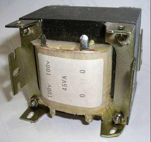
4 45VA -Ø Transformer 4
5 Single-phase transformer A simple single-phase transformer consists of two coils wound on a closed iron core as shown: Primary winding Secondary winding 5
6 Construction of Single-phase transformer Basically, a transformer has two windings: primary winding Secondary winding Each winding consists of many turns and are wound on a laminated iron core. The iron core is insulated with the windings. The core itself forms a closed iron magnetic circuit. Consequently, the windings encircle the core and the core encircles the windings. 6
7 Core type windings are wound around two legs of a magnetic core. Shell type windings are wound around the center leg of a threelegged magnetic core 7
8 Transformer action - Ideal Transformer Assumptions:. The winding resistances are negligible (R = 0). All fluxes are confined to the core and link both windings (leakage flux = 0) 3. Permeability of the core is infinite (I φ = 0) 4. o eddy current and hysteresis losses 8
9 Transformer action - Ideal Transformer (cont) When an A.C. voltage v applied to the primary winding: dφ v = e = () dt The core flux also links the secondary winding, then: dφ v = e = () dt From equations () and (): v v = = a 9
10 Transformer action - Ideal Transformer (cont) when a load is connected to the secondary winding, i will flow and will provide an mmf i for the core. i would immediately flow to establish another mmf i to oppose i since no mmf is required to establish a flux in the ideal core i i = 0 i = i Then: i i = = a 0
11 Transformer action - Ideal Transformer (cont) If the supply voltage is sinusoidal, then in rms values: Since V V = = a and I I = = a V = I V I input VA = output VA
12 Transformer action - Ideal Transformer (cont) Emf Equation of a Transformer (/) Φ = Φ m sinπft instantaneous value of induced emf/turn = dφ/dt volts = πfφ m cosπft volts = πfφ m sin(πft π/) volts
13 Transformer action - Ideal Transformer (cont) Emf Equation of a Transformer (/) rms value of induced emf / turn = x πfφ m volts = 4.44 x fφ m volts Hence E = 4.44 fφ m volts E = 4.44 fφ m volts E = E 3
14 Phasor Diagram of Ideal Transformer action under o-load EEE344 Electrical Machines V = E I m Φ E E =( / ) x E 4
15 Example A 00kVA, 6600/400V, 50 Hz single-phase transformer has 80 turns on the secondary. Calculate: a) the approximate values of the primary and secondary currents; b) the approximate number of primary turns; and c) the maximum value of the flux. Ans: 30.3A, 500A; 30; 0.05Wb 5
16 Features of Practical Transformer the windings have resistances not all windings link the same flux permeability of the core material is not infinite, and core losses occur when the core material is subjected to time-varying flux Losses in Practical Transformer Copper losses ( I R losses ) Iron losses ( Core losses ) 6
17 Transformer Losses Copper losses ( I R losses ) Power losses due to the resistances in the primary and secondary windings P C = I R + I R Iron losses ( Core losses ) a. Hysteresis loss Power loss due to the alignment of magnetic dipoles in the iron core b. Eddy current loss Power loss due to the induced eddy current circulating in the iron core 7
18 Parameters of Transformer In order to analyze transformer at different loading conditions, based on the principles of transformer action, equivalent circuit of practical transformer is worked out for calculation. R eq X eq R C X m Equivalent Circuit of Transformer The four essential parameters of the transformer equivalent circuit are then measured by Open-circuited test, and Short-circuited test on transformer 8
19 Three-Phase Transformer A set of three similar single phase transformers may be connected to form a three-phase transformer (three-phase transformer bank). The primary and secondary windings may be connected in either star or delta configurations. 9
20 Characteristics of Three-phase Transformer Bank Ease of transportation Inefficient magnetic circuit, less efficient Higher capital cost than a single one -phase of the transformer at fault, the other two are not affected 0
21 Construction of Three-phase Transformer Usually 3-limb core structure 5-limb core may be used to reduce the overall height of a 3-limb core Magnetic flux shares the magnetic circuit Fault on one-phase very likely affects the other two phases

22 Three-phase Transformer 3 limb core structure 3- phase transformer
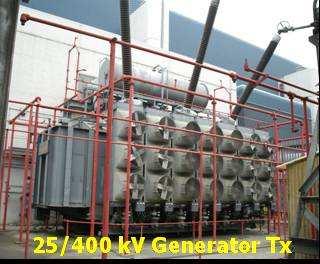
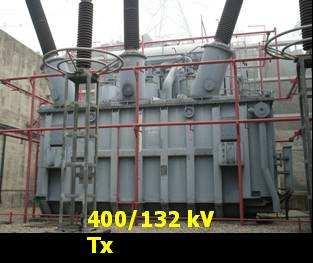
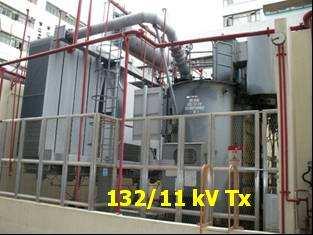
23 Three-phaseTransformers in T&D System 5kV Alternator Customers 3


24 3-Ø kv/380v Tx LV Side HV Side 4


25 Pole-mounted 3-Ø kv/380v Tx kv/380v 3-phase transformer fixed at a wooden pole 5
26 Turn ratio/voltage ratio/current ratio of 3-phase transformer (/4). STAR/delta ( Yd ) EEE344 Electrical Machines V V = 3.a = 3. ; I I = 3.a = 3. 6
27 Turn ratio/voltage ratio/current ratio of 3-phase transformer (/4). DELTA/star ( Dy ) EEE344 Electrical Machines V V = a 3 = 3. ; I I = 3 a = 3. 7
28 Turn ratio/voltage ratio/current ratio of 3-phase transformer (3/4) 3. DELTA/delta ( Dd ) EEE344 Electrical Machines V V = a = ; I I = a = 8
29 Turn ratio/voltage ratio/current ratio of 3-phase transformer (4/4) 4. STAR/star ( Yy ) EEE344 Electrical Machines V V = a = ; I I = a = 9
30 Auto-transformer transformer having a part of its windings common to the primary and secondary when a load is connected across b and c, then a current I will flow through the load. The current I will produce an m.m.f. in the core which will be balanced by a current I flowing in the complete winding 30
31 Auto-transformer The voltages and currents are related by the same turns ratio as in a two-winding transformer: V V = = a I I = = a 3
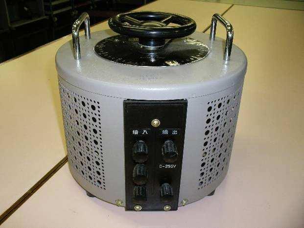
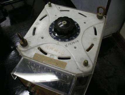
32 Single-phase Auto-transformer 3
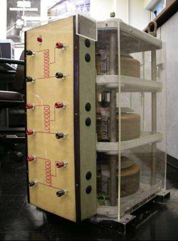
33 Three-phase Auto-transformer 33
34 Example EEE344 Electrical Machines A φ, 00 kva, 000/00 V two-winding transformer is connected as an autotransformer as shown such that more than 000 V is obtained at the secondary. The portion ab is the 00 V winding, and the portion bc is the 000 V winding. Compute the kva rating as an autotransformer. 34
35 Example (cont) The current rating of the winding are: 00,000 I ab = = 500A 00 00,000 I bc = = 50A,000 Therefore, for full-load operation of the autotransformer, the terminal currents are: I H = 500A I L = = 550A 35
36 Example (cont) ow, V L = 000V and V H = 00V Therefore, kva L = = kva H = = (ans) (ans) ote: A φ, 00 kva, two-winding transformer when connected as an autotransformer can deliver 00 kva. 36
37 Advantages of Auto-transformer It effects a saving in winding material (copper or aluminum), since the secondary winding is part of the primary current. Lower copper loss, therefore efficiency is higher than in the two winding transformer. Lower leakage reactances, lower exciting current. Variable output voltage can be obtained. 37
38 Disadvantage of Auto-Transformer There is a direct connection between the primary and secondary sides. Should an open-circuit develop between points b and c, the full mains voltage would be applied to the secondary. The short-circuit current is much larger than for normal two-winding transformer 38
39 Application of Auto-transformer Boosting or bucking of a supply voltage by a small amount. (The smaller difference voltage between the output and input voltages the greater is the saving of winding material.) Starting of a.c. machines, e.g. induction motor, where the voltage is raised in two or more steps from a small value to the full supply voltage. Continuously variable a.c. supply voltages, normally connected between a low voltage supply in and a high voltage supply out. Production of very high voltages, e.g. 75kV and 400kV grid system 39
40 Instrument Transformers Instrument transformers are used to reduce the voltage or current magnitudes so that the measuring ranges of measuring instruments can be extended. Measuring Instruments are connected to the secondary of the transformers. The measured values should then be multiplied by the appropriate turns ratio to get the actual primary values.. Voltage Transformer VT (or PT) / is large and standard 0 V at the secondary.. Current Transformer CT / is small and standard 5 A or A at the secondary. 40
41 Voltage Transformer (VT) Fundamentally similar in principle to power transformers but with rated outputs in VA rather than kva or MVA. Operating at full supply voltage, the secondary current is very small so that the transformers may be regarded in the same way as a power transformer on no load. Current Transformer (CT) Transforms large primary current value in terms of its magnitude and phase to a smaller secondary current value. the secondary value is directly proportional to the primary value. ominal CT ratio (60~3000A/5A, 30~000A/A) 4


42 Protection CT ominal CT ratio (000/5, 00/5) Required to operate at many times full load current. Linearity under these conditions is not of great importance. The essential point is that saturation must be high enough to drive the magnetizing current and the secondary current under fault condition. P Primary Insulatio n S Iron area S P Ring type CT terminal Markings Ring type CT Secondary 4
43 Metering CT For non-protection purpose Metering CTs need perform very accurately but only over the normal range of load up to about 0% full load current. 43
44 Reasons for using Instrument Transformer Do not require special designed instruments for h.v. or heavy current measurements (the instrument ranges could be standardized) Electrical isolation from the primary (h.v. side) is achievable For safety reason, one terminal of the secondary winding can be earthed 44
45 About the Use of Instrument Transformer may have turns ratio error phase shift may exist between primary and secondary measuring quantities. CT is actually a step-up transformer with very large turns ratio (eg 500/), excessive voltage will exist between the secondary terminals if they were left open. EVER LET THE SECODARY OF A C.T. OPE-CIRCUITED 45
46 Department of Electrical Engineering ED of Lecture Basic Operating Principles of Transformers
IVE(TY) Department of Engineering. Electrical Machines 1. Electrical Machines 1. Hour 13. slide 1
 Department of Engineering. Electrical Machines 1. Electrical Machines 1. Hour 13. slide 1") Hour 3 slide Three Phase Transformer (sect. 2.6) A set of three similar single phase transformers may be connected to form a three-phase transformer (three-phase transformer bank). The primary and secondary
Hour 3 slide Three Phase Transformer (sect. 2.6) A set of three similar single phase transformers may be connected to form a three-phase transformer (three-phase transformer bank). The primary and secondary
Chapter 2-1 Transformers
 Principles of Electric Machines and Power Electronics Chapter 2-1 Transformers Third Edition P. C. Sen Transformer application 1: power transmission Ideal Transformer Assumptions: 1. Negligible winding
148 Electric Machines
 148 Electric Machines 3.1 The emf per turn for a single-phase 2200/220- V, 50-Hz transformer is approximately 12 V. Calculate (a) the number of primary and secondary turns, and (b) the net cross-sectional
Walchand Institute of Technology. Basic Electrical and Electronics Engineering. Transformer
 Walchand Institute of Technology Basic Electrical and Electronics Engineering Transformer 1. What is transformer? explain working principle of transformer. Electrical power transformer is a static device
CHAPTER 2. Transformers. Dr Gamal Sowilam
 CHAPTER Transformers Dr Gamal Sowilam Introduction A transformer is a static machine. It is not an energy conversion device, it is indispensable in many energy conversion systems. A transformer essentially
UNIVERSITY OF TECHNOLOGY By: Fadhil A. Hasan ELECTRICAL MACHINES
 UNIVERSITY OF TECHNOLOGY DEPARTMENT OF ELECTRICAL ENGINEERING Year: Second 2016-2017 By: Fadhil A. Hasan ELECTRICAL MACHINES І Module-II: AC Transformers o Single phase transformers o Three-phase transformers
INSTITUTE OF AERONAUTICAL ENGINEERING (Autonomous) Dundigal, Hyderabad ELECTRICAL AND ELECTRONICS ENGINEERING
 Dundigal, Hyderabad ELECTRICAL AND ELECTRONICS ENGINEERING") Course Name Course Code Class Branch INSTITUTE OF AERONAUTICAL ENGINEERING (Autonomous) Dundigal, Hyderabad - 500 043 ELECTRICAL AND ELECTRONICS ENGINEERING QUESTION BANK : ELECRICAL MACHINES I : A40212
Course Name Course Code Class Branch INSTITUTE OF AERONAUTICAL ENGINEERING (Autonomous) Dundigal, Hyderabad - 500 043 ELECTRICAL AND ELECTRONICS ENGINEERING QUESTION BANK : ELECRICAL MACHINES I : A40212
INSTITUTE OF AERONAUTICAL ENGINEERING (Autonomous) Dundigal, Hyderabad
 Dundigal, Hyderabad") INSTITUTE OF AERONAUTICAL ENGINEERING (Autonomous) Dundigal, Hyderabad - 00 0 ELECTRICAL AND ELECTRONICS ENGINEERING QUESTION BANK Course Name Course Code Class Branch : ELECRICAL MACHINES - II : A0 :
INSTITUTE OF AERONAUTICAL ENGINEERING (Autonomous) Dundigal, Hyderabad - 00 0 ELECTRICAL AND ELECTRONICS ENGINEERING QUESTION BANK Course Name Course Code Class Branch : ELECRICAL MACHINES - II : A0 :
86 chapter 2 Transformers
 86 chapter 2 Transformers Wb 1.2x10 3 0 1/60 2/60 3/60 4/60 5/60 6/60 t (sec) 1.2x10 3 FIGURE P2.2 2.3 A single-phase transformer has 800 turns on the primary winding and 400 turns on the secondary winding.
Transformers. gpmacademics.weebly.com
 TRANSFORMERS Syllabus: Principles of operation, Constructional Details, Losses and efficiency, Regulation of Transformer, Testing: OC & SC test. TRANSFORMER: It is a static device which transfers electric
WELCOME TO THE LECTURE
 WLCOM TO TH LCTUR ON TRNFORMR Single Phase Transformer Three Phase Transformer Transformer transformer is a stationary electric machine which transfers electrical energy (power) from one voltage level
INSTITUTE OF AERONAUTICAL ENGINEERING (Autonomous) Dundigal, Hyderabad
 Dundigal, Hyderabad") INSTITUTE OF AERONAUTICAL ENGINEERING (Autonomous) Dundigal, Hyderabad - 00 03 ELECTRICAL AND ELECTRONICS ENGINEERING ASSIGNMENT Course Name : ELECRICAL MACHINES - II Course Code : A0 Class : II B.TECH-II
INSTITUTE OF AERONAUTICAL ENGINEERING (Autonomous) Dundigal, Hyderabad - 00 03 ELECTRICAL AND ELECTRONICS ENGINEERING ASSIGNMENT Course Name : ELECRICAL MACHINES - II Course Code : A0 Class : II B.TECH-II
The power transformer
 ELEC0014 - Introduction to power and energy systems The power transformer Thierry Van Cutsem t.vancutsem@ulg.ac.be www.montefiore.ulg.ac.be/~vct November 2017 1 / 35 Power transformers are used: to transmit
AUTO-TRANSFORMER. This is having only one winding; part of this winding is common to both primary and secondary.
 AUTO-TRANSFORMER This is having only one winding; part of this winding is common to both primary and secondary. In 2-winding transformer both primary and secondary windings are electrically isolated, but
SHRI RAMSWAROOP MEMORIAL COLLEGE OF ENGG. & MANAGEMENT
 SHRI RAMSWAROOP MEMORIAL COLLEGE OF ENGG. & MANAGEMENT B.Tech. [SEM I (CE,EC,EE,EN)] QUIZ TEST-3 (Session: 2012-13) Time: 1 Hour ELECTRICAL ENGINEERING Max. Marks: 30 (EEE-101) Roll No. Academic/26 Refer/WI/ACAD/18
INSTITUTE OF AERONAUTICAL ENGINEERING (Autonomous) Dundigal, Hyderabad
 Dundigal, Hyderabad") INSTITUTE OF AERONAUTICAL ENGINEERING (Autonomous) Dundigal, Hyderabad -00 03 ELECTRCIAL AND ELECTRONICS ENGINEERING TUTORIAL QUESTION BANK Course Name Course Code Class Branch : DC MACHINES AND TRANSFORMERS
INSTITUTE OF AERONAUTICAL ENGINEERING (Autonomous) Dundigal, Hyderabad -00 03 ELECTRCIAL AND ELECTRONICS ENGINEERING TUTORIAL QUESTION BANK Course Name Course Code Class Branch : DC MACHINES AND TRANSFORMERS
Spring 2000 EE361: MIDTERM EXAM 1
 NAME: STUDENT NUMBER: Spring 2000 EE361: MIDTERM EXAM 1 This exam is open book and closed notes. Assume f=60 hz and use the constant µ o =4π 10-7 wherever necessary. Be sure to show all work clearly. 1.
By Gill ( ) PDF created with FinePrint pdffactory trial version
 PDF created with FinePrint pdffactory trial version") By Gill (www.angelfire.com/al4/gill ) 1 Introduction One of the main reasons of adopting a.c. system instead of d.c. for generation, transmission and distribution of electrical power is that alternatin
By Gill (www.angelfire.com/al4/gill ) 1 Introduction One of the main reasons of adopting a.c. system instead of d.c. for generation, transmission and distribution of electrical power is that alternatin
3. What is hysteresis loss? Also mention a method to minimize the loss. (N-11, N-12)
") DHANALAKSHMI COLLEGE OF ENGINEERING, CHENNAI DEPARTMENT OF ELECTRICAL AND ELECTRONICS ENGINEERING EE 6401 ELECTRICAL MACHINES I UNIT I : MAGNETIC CIRCUITS AND MAGNETIC MATERIALS Part A (2 Marks) 1. List
DHANALAKSHMI COLLEGE OF ENGINEERING, CHENNAI DEPARTMENT OF ELECTRICAL AND ELECTRONICS ENGINEERING EE 6401 ELECTRICAL MACHINES I UNIT I : MAGNETIC CIRCUITS AND MAGNETIC MATERIALS Part A (2 Marks) 1. List
MAHARASHTRA STATE BOARD OF TECHNICAL EDUCATION
 Important Instructions to examiners: 1) The answers should be examined by key words and not as word-to-word as given in the model answer scheme. 2) The model answer and the answer written by candidate
Module 1. Introduction. Version 2 EE IIT, Kharagpur
 Module 1 Introduction Lesson 1 Introducing the Course on Basic Electrical Contents 1 Introducing the course (Lesson-1) 4 Introduction... 4 Module-1 Introduction... 4 Module-2 D.C. circuits.. 4 Module-3
TRANSFORMERS PART A. 2. What is the turns ratio and transformer ratio of transformer? Turns ratio = N2/ N1 Transformer = E2/E1 = I1/ I2 =K
 UNIT II TRANSFORMERS PART A 1. Define a transformer? A transformer is a static device which changes the alternating voltage from one level to another. 2. What is the turns ratio and transformer ratio of
Code No: R Set No. 1
 Code No: R05220204 Set No. 1 II B.Tech II Semester Supplimentary Examinations, Aug/Sep 2007 ELECTRICAL MACHINES-II (Electrical & Electronic Engineering) Time: 3 hours Max Marks: 80 Answer any FIVE Questions
UNIT 4 TRANSFORMER 4.1 INTRODUCTION. Structure. 4.1 Introduction. 4.2 Basics of Transformer. 4.3 Equivalent Circuit of Transformer
 UT 4 TRASFORMR Transformer Structure 4. ntroduction Objectives 4. Basics of Transformer 4.. ntroduction 4.. MF quation of a Transformer 4..3 Construction 4.3 quivalent Circuit of Transformer 4.3. quivalent
Module 7. Transformer. Version 2 EE IIT, Kharagpur
 Module 7 Transformer Lesson 28 Problem solving on Transformers Contents 28 Problem solving on Transformer (Lesson-28) 4 28.1 Introduction. 4 28.2 Problems on 2 winding single phase transformers. 4 28.3
CHAPTER 4. Distribution Transformers
 CHAPTER 4 Distribution Transformers Introduction A transformer is an electrical device that transfers energy from one circuit to another purely by magnetic coupling. Relative motion of the parts of the
Aligarh College of Engineering & Technology (College Code: 109) Affiliated to UPTU, Approved by AICTE Electrical Engg.
 Affiliated to UPTU, Approved by AICTE Electrical Engg.") Aligarh College of Engineering & Technology (College Code: 19) Electrical Engg. (EE-11/21) Unit-I DC Network Theory 1. Distinguish the following terms: (a) Active and passive elements (b) Linearity and
Aligarh College of Engineering & Technology (College Code: 19) Electrical Engg. (EE-11/21) Unit-I DC Network Theory 1. Distinguish the following terms: (a) Active and passive elements (b) Linearity and
ELECTRICAL ENGINEERING ESE TOPIC WISE OBJECTIVE SOLVED PAPER-II
 ELECTRICAL ENGINEERING ESE TOPIC WISE OBJECTIVE SOLVED PAPER-II From (1992 2017) Office : F-126, (Lower Basement), Katwaria Sarai, New Delhi-110016 Phone : 011-26522064 Mobile : 8130909220, 9711853908
Electrical Machines I : Transformers
 UNIT TRANSFORMERS PART A (Q&A) 1. What is step down transformer? The transformer used to step down the voltage from primary to secondary is called as step down transformer. (Ex: /11).. Draw the noload
Module 7. Transformer. Version 2 EE IIT, Kharagpur
 Module 7 Transformer Lesson 3 Ideal Transformer Contents 3 Ideal Transformer (Lesson: 3) 4 3. Goals of the lesson 4 3. Introduction.. 5 3.. Principle of operation.. 5 3.3 Ideal Transformer.. 6 3.3. Core
ECE 3600 Transformers b
 Transformer basics and ratings A Transformer is two coils of wire that are magnetically coupled. Transformers b Transformers are only useful for AC, which is one of the big reasons electrical power is
Hours / 100 Marks Seat No.
 17415 15162 3 Hours / 100 Seat No. Instructions (1) All Questions are Compulsory. (2) Answer each next main Question on a new page. (3) Illustrate your answers with neat sketches wherever necessary. (4)
~=E.i!=h. Pre-certification Transformers
 7 Transformers Section 26 of the electrical code governs the use and installations of transformers. A transformer is a static device used to transfer energy from one alternating current circuit to another.
Engineering Science OUTCOME 4 - TUTORIAL 3 CONTENTS. 1. Transformers
 Unit : Unit code: QCF Level: 4 Credit value: 5 SYLLABUS Engineering Science L/60/404 OUTCOME 4 - TUTOIAL 3 Be able to apply single phase AC theory to solve electrical and electronic engineering problems
SECTION 4 TRANSFORMERS. Yilu (Ellen) Liu. Associate Professor Electrical Engineering Department Virginia Tech University
 Liu. Associate Professor Electrical Engineering Department Virginia Tech University") SECTION 4 TRANSFORMERS Yilu (Ellen) Liu Associate Professor Electrical Engineering Department Virginia Tech University Analysis of Transformer Turns Ratio......................... 4.2 Analysis of a Step-Up
SECTION 4 TRANSFORMERS Yilu (Ellen) Liu Associate Professor Electrical Engineering Department Virginia Tech University Analysis of Transformer Turns Ratio......................... 4.2 Analysis of a Step-Up
TRANSFORMER THEORY. Mutual Induction
 Transformers Transformers are used extensively for AC power transmissions and for various control and indication circuits. Knowledge of the basic theory of how these components operate is necessary to
El-Hawary, M.E. The Transformer Electrical Energy Systems. Series Ed. Leo Grigsby Boca Raton: CRC Press LLC, 2000
 El-Hawary, M.E. The Transformer Electrical Energy Systems. Series Ed. Leo Grigsby Boca Raton: CRC Press LLC, 000 97 Chapter 4 THE TRANSFORMER 4. NTRODUCTON The transformer is a valuable apparatus in electrical
MAHARASHTRA STATE BOARD OF TECHNICAL EDUCATION
 Important Instructions to examiners: 1) The answers should be examined by key words and not as word-to-word as given in the model answer scheme. 2) The model answer and the answer written by candidate
SYNCHRONOUS MACHINES
 SYNCHRONOUS MACHINES The geometry of a synchronous machine is quite similar to that of the induction machine. The stator core and windings of a three-phase synchronous machine are practically identical
EE2022 Electrical Energy Systems
 EE0 Electrical Energy Systems Lecture : Transformer and Per Unit Analysis 7-0-0 Panida Jirutitijaroen Department of Electrical and Computer Engineering /9/0 EE0: Transformer and Per Unit Analysis by P.
VALLIAMMAI ENGINEERING COLLEGE
 VALLIAMMAI ENGINEERING COLLEGE SRM Nagar, Kattankulathur 603 203 DEPARTMENT OF ELECTRONICS AND INSTRUMENTATION ENGINEERING QUESTION BANK IV SEMESTER EI6402 ELECTRICAL MACHINES Regulation 2013 Academic
Transformer & Induction M/C
 UNIT- 2 SINGLE-PHASE TRANSFORMERS 1. Draw equivalent circuit of a single phase transformer referring the primary side quantities to secondary and explain? (July/Aug - 2012) (Dec 2012) (June/July 2014)
PROBLEMS on Transformers
 PROBLEMS on Transformers (A) Simple Problems 1. A single-phase, 250-kVA, 11-kV/415-V, 50-Hz transformer has 80 turns on the secondary. Calculate (a) the approximate values of the primary and secondary
Practical Transformer on Load
 Practical Transformer on Load We now consider the deviations from the last two ideality conditions : 1. The resistance of its windings is zero. 2. There is no leakage flux. The effects of these deviations
Transformers. Department of Physics & Astronomy Texas Christian University, Fort Worth, TX. April 23, 2013
 Transformers Department of Physics & Astronomy Texas Christian University, Fort Worth, TX April 23, 2013 1 Introduction In the early nineteenth century, Hans Christian Øersted discovered that a magnetic
Table of Contents. Table of Figures. Table of Tables
 Abstract The aim of this report is to investigate and test a transformer and check if it is good to use by doing the following tests continuity test, insulation test, polarity test, open circuit test,
ECG 741 Power Distribution Transformers. Y. Baghzouz Spring 2014
 ECG 741 Power Distribution Transformers Y. Baghzouz Spring 2014 Preliminary Considerations A transformer is a device that converts one AC voltage to another AC voltage at the same frequency. The windings
PHYS 1441 Section 001 Lecture #22 Wednesday, Nov. 29, 2017
 PHYS 1441 Section 001 Lecture #22 Chapter 29:EM Induction & Faraday s Law Transformer Electric Field Due to Changing Magnetic Flux Chapter 30: Inductance Mutual and Self Inductance Energy Stored in Magnetic
UNIT II MEASUREMENT OF POWER & ENERGY
 UNIT II MEASUREMENT OF POWER & ENERGY Dynamometer type wattmeter works on a very simple principle which is stated as "when any current carrying conductor is placed inside a magnetic field, it experiences
SHRI RAMSWAROOP MEMORIAL COLLEGE OF ENGG. & MANAGEMENT B.Tech. [SEM I (EE, EN, EC, CE)] QUIZ TEST-3 (Session: ) Time: 1 Hour ELECTRICAL ENGINEE
![SHRI RAMSWAROOP MEMORIAL COLLEGE OF ENGG. & MANAGEMENT B.Tech. [SEM I (EE, EN, EC, CE)] QUIZ TEST-3 (Session: ) Time: 1 Hour ELECTRICAL ENGINEE](/thumbs/94/118213481.jpg "SHRI RAMSWAROOP MEMORIAL COLLEGE OF ENGG. & MANAGEMENT B.Tech. [SEM I (EE, EN, EC, CE)] QUIZ TEST-3 (Session: ) Time: 1 Hour ELECTRICAL ENGINEE") SHRI RAMSWAROOP MEMORIAL COLLEGE OF ENGG. & MANAGEMENT B.Tech. [SEM I (EE, EN, EC, CE)] QUIZ TEST-3 (Session: 2014-15) Time: 1 Hour ELECTRICAL ENGINEERING Max. Marks: 30 (NEE-101) Roll No. Academic/26
SHRI RAMSWAROOP MEMORIAL COLLEGE OF ENGG. & MANAGEMENT B.Tech. [SEM I (EE, EN, EC, CE)] QUIZ TEST-3 (Session: 2014-15) Time: 1 Hour ELECTRICAL ENGINEERING Max. Marks: 30 (NEE-101) Roll No. Academic/26
Chapter 16: Mutual Inductance
 Chapter 16: Mutual Inductance Instructor: Jean-François MILLITHALER http://faculty.uml.edu/jeanfrancois_millithaler/funelec/spring2017 Slide 1 Mutual Inductance When two coils are placed close to each
Trade of Electrician. The Transformer
 Trade of Electrician Standards Based Apprenticeship The Transformer Phase 2 Module No. 2.1 Unit No. 2.1.10 COURSE NOTES Created by Gerry Ryan - Galway TC Revision 1 April 2000 by Gerry Ryan - Galway TC
PHYS 1444 Section 501 Lecture #20
 PHYS 1444 Section 501 Lecture #0 Monday, Apr. 17, 006 Transformer Generalized Faraday s Law Inductance Mutual Inductance Self Inductance Inductor Energy Stored in the Magnetic Field 1 Announcements Quiz
QUESTION BANK ETE (17331) CM/IF. Chapter1: DC Circuits
 CM/IF. Chapter1: DC Circuits") QUESTION BANK ETE (17331) CM/IF Chapter1: DC Circuits Q1. State & explain Ohms law. Also explain concept of series & parallel circuit with the help of diagram. 3M Q2. Find the value of resistor in fig.
QUESTION BANK ETE (17331) CM/IF Chapter1: DC Circuits Q1. State & explain Ohms law. Also explain concept of series & parallel circuit with the help of diagram. 3M Q2. Find the value of resistor in fig.
Chapter 33. Alternating Current Circuits
 Chapter 33 Alternating Current Circuits Alternating Current Circuits Electrical appliances in the house use alternating current (AC) circuits. If an AC source applies an alternating voltage to a series
PART A. 1. List the types of DC Motors. Give any difference between them. BTL 1 Remembering
 UNIT I DC MACHINES Three phase circuits, a review. Construction of DC machines Theory of operation of DC generators Characteristics of DC generators Operating principle of DC motors Types of DC motors
TRANSFORMER OPERATION
 Chapter 3 TRANSFORMER OPERATION 1 A transformer is a static device (no moving parts) used to transfer energy from one AC circuit to another. This transfer of energy may involve an increase or decrease
EE 221 Circuits II. Chapter 13 Magnetically Coupled Circuits
 EE Circuits II Chapter 3 Magnetically Coupled Circuits Magnetically Coupled Circuits 3. What is a transformer? 3. Mutual Inductance 3.3 Energy in a Coupled Circuit 3.4 inear Transformers 3.5 Ideal Transformers
3.1.Introduction. Synchronous Machines
 3.1.Introduction Synchronous Machines A synchronous machine is an ac rotating machine whose speed under steady state condition is proportional to the frequency of the current in its armature. The magnetic
THE UNIVERSITY OF BRITISH COLUMBIA. Department of Electrical and Computer Engineering. EECE 365: Applied Electronics and Electromechanics
 THE UNIVERSITY OF BRITISH COLUMBIA Department of Electrical and Computer Engineering EECE 365: Applied Electronics and Electromechanics Final Exam / Sample-Practice Exam Spring 2008 April 23 Topics Covered:
HPS Universal BUCK-BOOST TRANSFORMERS
 BUCK-BOOST TRANSFORMERS Single and Three Phase Potted Buck-Boost Transformers Buck-Boost Applications & Standard Specification... 80 Selecting Buck-Boost Transformers... 81 Single Phase Selection Tables...
Power systems 2: Transformation
 Power systems 2: Transformation Introduction In this series of articles, we will be looking at each of the main stages of the electrical power system in turn. s you will recall from our Introduction to
Unit Transformers
 Unit 11.08 Transformers Prepared in Dec 1998 Second editing in march 2000 Learning objectives At the end of this unit you should be able to : 1. describe the structure and principle of operation of a basic
A Practical Guide to Free Energy Devices
 A Practical Guide to Free Energy Devices Part PatD14: Last updated: 25th February 2006 Author: Patrick J. Kelly This patent application shows the details of a device which it is claimed, can produce sufficient
INSTITUTE OF AERONAUTICAL ENGINEERING (Autonomous) Dundigal, Hyderabad
 Dundigal, Hyderabad") I INSTITUTE OF AERONAUTICAL ENGINEERING (Autonomous) Dundigal, Hyderabad-500043 CIVIL ENGINEERING TUTORIAL QUESTION BANK Course Name : BASIC ELECTRICAL AND ELECTRONICS ENGINEERING Course Code : AEE018
I INSTITUTE OF AERONAUTICAL ENGINEERING (Autonomous) Dundigal, Hyderabad-500043 CIVIL ENGINEERING TUTORIAL QUESTION BANK Course Name : BASIC ELECTRICAL AND ELECTRONICS ENGINEERING Course Code : AEE018
Department of Electrical and Computer Engineering Lab 6: Transformers
 ESE Electronics Laboratory A Department of Electrical and Computer Engineering 0 Lab 6: Transformers. Objectives ) Measure the frequency response of the transformer. ) Determine the input impedance of
EQUIVALENT CIRCUIT OF A SINGLE-PHASE TRANSFORMER
 Electrical Machines Lab Experiment-No. One Date: 15-11-2016 EQUIVALENT CIRCUIT OF A SINGLE-PHASE TRANSFORMER Aim: The determination of electrical equivalent circuit parameters of a single phase power transformer
HIGH VOLTAGE ENGINEERING(FEEE6402) LECTURER-24
 LECTURER-24") LECTURER-24 GENERATION OF HIGH ALTERNATING VOLTAGES When test voltage requirements are less than about 300kV, a single transformer can be used for test purposes. The impedance of the transformer should
LECTURER-24 GENERATION OF HIGH ALTERNATING VOLTAGES When test voltage requirements are less than about 300kV, a single transformer can be used for test purposes. The impedance of the transformer should
Introduction : Design detailed: DC Machines Calculation of Armature main Dimensions and flux for pole. Design of Armature Winding & Core.
 Introduction : Design detailed: DC Machines Calculation of Armature main Dimensions and flux for pole. Design of Armature Winding & Core. Design of Shunt Field & Series Field Windings. Design detailed:
CHIEF ENGINEER REG III/2 MARINE ELECTROTECHNOLOGY
 CHIEF ENGINEER REG III/2 MARINE ELECTROTECHNOLOGY LIST OF TOPICS 1 Electric Circuit Principles 2 Electronic Circuit Principles 3 Generation 4 Distribution 5 Utilisation The expected learning outcome is
VOLTECHNOTES. Transformer Basics VPN /1
 Transformer Basics VPN 104-039/1 TRANSFORMER BASICS Introduction Transformer design and test are sometimes viewed as an art rather than a science. Transformers are imperfect devices, and there will be
MAHARASHTRA STATE BOARD OF TECHNICAL EDUCATION
 Important Instructions to examiners: 1) The answers should be examined by key words and not as word-to-word as given in the model answer scheme. 2) The model answer and the answer written by candidate
ELECTRICAL MACHINES - II COURSEFILE
 ELECTRICAL MACHINES - II COURSEFILE Coursefile contents: 1. Cover Page 2. Syllabus copy 3. Vision of the department 4. Mission of the department 5. PEOs and POs 6. Course objectives and outcomes 7. Brief
ISSN: X Impact factor: (Volume 3, Issue 6) Available online at Modeling and Analysis of Transformer
 Available online at Modeling and Analysis of Transformer") ISSN: 2454-132X Impact factor: 4.295 (Volume 3, Issue 6) Available online at www.ijariit.com Modeling and Analysis of Transformer Divyapradeepa.T Department of Electrical and Electronics, Rajalakshmi Engineering
ISSN: 2454-132X Impact factor: 4.295 (Volume 3, Issue 6) Available online at www.ijariit.com Modeling and Analysis of Transformer Divyapradeepa.T Department of Electrical and Electronics, Rajalakshmi Engineering
PESIT Bangalore South Campus Hosur road, 1km before Electronic City, Bengaluru -100 Department of Electronics & Communication Engineering
 INTERNAL ASSESSMENT TEST 3 Date : 15/11/16 Marks: 0 Subject & Code: BASIC ELECTRICAL ENGINEERING -15ELE15 Sec : F,G,H,I,J,K Name of faculty : Mrs.Hema, Mrs.Dhanashree, Mr Nagendra, Mr.Prashanth Time :
PHYS 1444 Section 003 Lecture #19
 PHYS 1444 Section 003 Lecture #19 Monday, Nov. 14, 2005 Electric Generators DC Generator Eddy Currents Transformer Mutual Inductance Today s homework is homework #10, due noon, next Tuesday!! 1 Announcements
Code No: R Set No. 1
 Code No: R05310204 Set No. 1 III B.Tech I Semester Regular Examinations, November 2007 ELECTRICAL MACHINES-III (Electrical & Electronic Engineering) Time: 3 hours Max Marks: 80 Answer any FIVE Questions
Reg. No. : BASIC ELECTRICAL TECHNOLOGY (ELE 101)
") Department of Electrical and Electronics Engineering Reg. No. : MNIPL INSTITUTE OF TECHNOLOGY, MNIPL ( Constituent Institute of Manipal University, Manipal) FIRST SEMESTER B.E. DEGREE MKEUP EXMINTION (REVISED
Department of Electrical and Electronics Engineering Reg. No. : MNIPL INSTITUTE OF TECHNOLOGY, MNIPL ( Constituent Institute of Manipal University, Manipal) FIRST SEMESTER B.E. DEGREE MKEUP EXMINTION (REVISED
MAHARASHTRA STATE BOARD OF TECHNICAL EDUCATION
 Important Instructions to examiners: 1. The answers should be examined by key words and not as word-to-word as given in the model answer scheme. 2. The model answer and the answer written by candidate
Transformer Trainer. Electrical Power Systems PSL20. Learning Outcomes. Key Features. Key Specifications
 Electrical Power Systems PSL2 Investigates the principles and operating characteristics of single-phase and three-phase power and distribution transformers Key Features Educational transformers with fully
Power. Power is the rate of using energy in joules per second 1 joule per second Is 1 Watt
 3 phase Power All we need electricity for is as a source of transport for energy. We can connect to a battery, which is a source of stored energy. Or we can plug into and electric socket at home or in
EE 340 Power Transformers
 EE 340 Power Transformers Preliminary considerations A transformer is a device that converts one AC voltage to another AC voltage at the same frequency. It consists of one or more coil(s) of wire wrapped
Review 6. unlike poles cause the magnets to attract. like poles cause the magnets to repel.
 Review 6 1. The two characteristics of all magnets are: they attract and hold Iron, and, if free to move, they will assume roughly a south - north position. 2. Lines of flux always leave the north pole
PRACTICAL WORK BOOK. Basic Electrical & Electronics Engineering BE-104
 PRACTICAL WORK BOOK Basic Electrical & Electronics Engineering BE-104 Name: Enrollment No: Branch: Semester: Batch: Institute: Department of Electrical Engineering I N D E X S.NO. EXPERIMENT NAME DATE
EN Assignment No.1 - TRANSFORMERS
 EN-06 - Assignment No.1 - TRANSFORMERS Date : 13 th Jan 01 Q1) A 0kVA 00/0 Volts, 60Hz, single phase transformer is found to have the following equivalent circuit parameter referred to the high potential
Unit 3 Magnetism...21 Introduction The Natural Magnet Magnetic Polarities Magnetic Compass...21
 Chapter 1 Electrical Fundamentals Unit 1 Matter...3 Introduction...3 1.1 Matter...3 1.2 Atomic Theory...3 1.3 Law of Electrical Charges...4 1.4 Law of Atomic Charges...4 Negative Atomic Charge...4 Positive
Review: Lecture 9. Instantaneous and Average Power. Effective or RMS Value. Apparent Power and Power Factor. Complex Power. Conservation of AC Power
 Review: Lecture 9 Instantaneous and Average Power p( t) VmI m cos ( v i ) VmI m cos ( t v i ) Maximum Average Power Transfer Z L R L jx Effective or RMS Value I rms I m L R P * TH Apparent Power and Power
APPENDIX 4 TYPICAL LAYOUT, VALUES AND CONSTANTS
 109 APPENDIX 4 TYPICAL LAYOUT, VALUES AND CONSTANTS TYPICAL LAYOUT The purpose of a transformer is to transfer energy from the input to the output through the magnetic field. The layout of a partial typical
 VIDYARTHIPLUS - ANNA UNIVERSITY ONLINE STUDENTS COMMUNITY UNIT 1 DC MACHINES PART A 1. State Faraday s law of Electro magnetic induction and Lenz law. 2. Mention the following functions in DC Machine (i)
APPLICATION NOTE - 018
 APPLICATION NOTE - 018 Power Transformers Background Power Transformers are used within an AC power distribution systems to increase or decrease the operating voltage to achieve the optimum transmission
Transformers 21.1 INTRODUCTION 21.2 MUTUAL INDUCTANCE
 21 Transformers 21.1 INTRODUCTION Chapter 12 discussed the self-inductance of a coil. We shall now examine the mutual inductance that exists between coils of the same or different dimensions. Mutual inductance
Downloaded From All JNTU World
 Code: 9A02403 GENERATION OF ELECTRIC POWER 1 Discuss the advantages and disadvantages of a nuclear plant as compared to other conventional power plants. 2 Explain about: (a) Solar distillation. (b) Solar
PHYS 1442 Section 004 Lecture #15
 PHYS 1442 Section 004 Lecture #15 Monday March 17, 2014 Dr. Andrew Brandt Chapter 21 Generator Transformer Inductance 3/17/2014 1 PHYS 1442-004, Dr. Andrew Brandt Announcements HW8 on Ch 21-22 will be
ECE 241L Fundamentals of Electrical Engineering. Experiment 8 A-C Transformer, Magnetization & Hysteresis
 ECE 241L Fundamentals of Electrical Engineering Experiment 8 A-C Transformer, Magnetization & Hysteresis A. Objectives: I. Measure leakage inductance and resistance loss II. Measure magnetization inductance
TRANSFORMERS INTRODUCTION
 Tyco Electronics Corporation Crompton Instruments 1610 Cobb International Parkway, Unit #4 Kennesaw, GA 30152 Tel. 770-425-8903 Fax. 770-423-7194 TRANSFORMERS INTRODUCTION A transformer is a device that
Units. In the following formulae all lengths are expressed in centimeters. The inductance calculated will be in micro-henries = 10-6 henry.
 INDUCTANCE Units. In the following formulae all lengths are expressed in centimeters. The inductance calculated will be in micro-henries = 10-6 henry. Long straight round wire. If l is the length; d, the
Electromagnetic Induction
 Chapter 16 Electromagnetic Induction In This Chapter: Electromagnetic Induction Faraday s Law Lenz s Law The Transformer Self-Inductance Inductors in Combination Energy of a Current-Carrying Inductor Electromagnetic
COLLEGE OF ENGINEERING DEPARTMENT OF ELECTRICAL AND ELECTRONICS ENGINEERING ACADEMIC YEAR / EVEN SEMESTER QUESTION BANK
 KINGS COLLEGE OF ENGINEERING DEPARTMENT OF ELECTRICAL AND ELECTRONICS ENGINEERING ACADEMIC YEAR 2010-2011 / EVEN SEMESTER QUESTION BANK SUBJECT CODE & NAME: EE 1352 - ELECTRICAL MACHINE DESIGN YEAR / SEM
Transformer Factory Testing
 Transformer Factory Testing John J. Foschia Test Engineer John.Foschia@spx.com September 2018 Reasons for Testing Compliance with user specifications Assessment of quality and reliability Verification
Lecture 4 Power System Instrumentation. Course map
 Lecture 4 Power System Instrumentation 1 Course map 2 1 Outline of the Lecture Instrument Transformers Voltage Transformer Current Transformers Measurement Setups Instrumentation 3 The Current Transformer