CHAPTER 2. Transformers. Dr Gamal Sowilam
|
|
|
- Annice Marsh
- 5 years ago
- Views:
Transcription
1 CHAPTER Transformers Dr Gamal Sowilam
2 Introduction A transformer is a static machine. It is not an energy conversion device, it is indispensable in many energy conversion systems. A transformer essentially consists of two or more windings coupled by a mutual magnetic field. Ferromagnetic cores are used to provide tight magnetic coupling and high flux densities, known as iron core transformer. They are used in high-power applications. Air core transformers have poor magnetic coupling and are sometimes used in low-power electronic circuits.
3 Two types of core construction are normally used. 1. In the core type, The windings are wound around two legs of a magnetic core of rectangular shape.
4 In the shell type, the windings are wound around the center leg of three-legged magnetic core. To reduce core losses, the magnetic core is formed of a stack of thin laminations. L-shaped laminations are used for core-type construction and E- shaped laminations are used for shell-type construction.
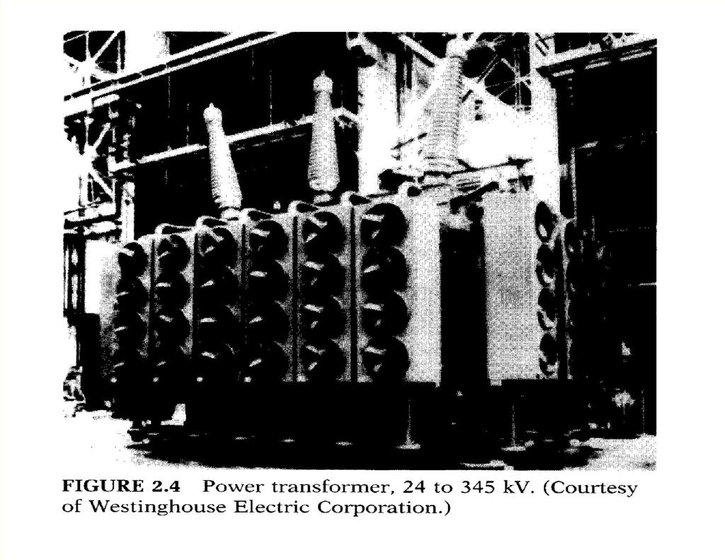
5 Power Transformer
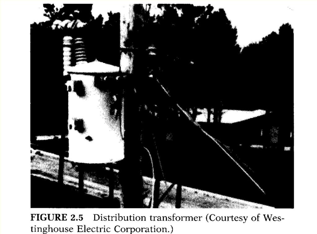
6 Distribution transformer
7 A schematic representation of a two-winding transformer is shown in the figure. Two vertical bars are used to signify tight magnetic coupling between the windings. One winding is connected to an ac supply, referred to as the primary winding. The other winding is connected to a load, referred to as the secondary winding.
8 Transformer Use Transformer primary function is to change voltage level. Transformers are used to step up and step down voltage at various stages of power transmission. Electric power is generated in a power house at about 30 kv and it is used in domestic house at 110 or 0 V. Electric power is transmitted at 00 kv to 500 kv.
9 Ideal Transformer Consider a two-windings transformer as shown in Fig. Ideal transformer has the following properties: Winding resistances are negligible. No leakage fluxes and core losses are negligible. Permeability of the core is infinite, the exciting current to establish flux in the core is negligible.
10 When the primary winding is connected to a voltage v 1 a voltage e 1 emf will be induced, v1 N1 The core flux also links the secondary winding and induce a voltage e, From the two equations, e e 1 v N d dt d dt v v 1 N N 1 a
11 Because the net mmf required to establish a flux in the ideal core is zero, N i i i N i N N N N 1 i i 1 a net mmf 0 The currents in the windings are inversely proportional to the number of turns. The instantaneous power is: The input VA at primary winding = The output VA at secondary winding v i v i 1 1
12 Example 0 There are 400 turns of wire in an iron-core coil. If this coil is to be used as the primary of a transformer, how many turns must be wound on the coil to form the secondary winding of the transformer to have a secondary voltage of 1 V if the primary voltage is 5 volts?
13 If the supply voltage v1 is sinusoidal, then the previous equation can be written in the terms of rms values:

14 Impedance transfer ازى تشوف المعاوقة من جھة الاولى او الثانیة ھام جدا so
15 An impedance from the primary side can also be transferred to the secondary side, and in that case its value has to be divided by the square of the turns ratio. An impedance Z connected in the secondary will appear as an impedance Z looking from the primary. An impedance from the primary side can also be transferred to the secondary side, and in that case its value has to be divided by the square of the turns ratio:
16 Example 1 A speaker of 9 resistive impedance is connected to a supply of 10 V with internal resistive impedance of 1, as shown in Figure. (a) Determine the power absorbed by the speaker. (b) To maximize the power transfer to the speaker, a transformer of 1: 3 turns ratio is used between source and speaker as shown in Figure. Determine the power taken by the speaker. [ (a) 9W (b) 5W


17 Polarity determination Consider the two windings shown. Terminals 1 & 3 are identical, because Currents entering these terminals produce fluxes in the same direction in the Core forms the common magnetic path.
18 Polarities of windings must be known if transformers are connected in parallel. To share a common load. Fig. shows the parallel connection of two single-phase Transformers.
19 Practical Transformer In a practical transformer, the windings have resistances, leakage flux exists, core losses occur, and the permeability of the core material is not infinite.
20 In the effects of winding resistance and leakage flux, the transformer windings are tightly coupled by a mutual flux. The effects of leakage flux can be accounted for by an inductance, called Leakage inductance.
21 In practical transformer, a magnetizing current is required to establish a flux in the core. This effect can be represented by a magnetizing inductance L m The core loss can be represented by a resistance R c. A practical transformer is therefore equivalent to an ideal transformer plus external impedances that represent imperfections of an actual transformer.
22 Equivalent Circuit The ideal transformer can be moved to the right or left by referring all quantities to the primary or secondary side. The equivalent circuit with the ideal transformer moved to the right is shown in the Figure.
23 Referred Equivalent Circuit For convenience, the ideal transformer is usually not shown and the equivalent circuit is drawn as shown in the Figure. All quantities referred to one side. The referred quantities are indicated with primes.
24 Approximate Equivalent Circuit The voltage drops I 1 R 1 and I 1 X l1 are normally small and E 1 V 1 (see Figure). Approximate Equivalent circuit simplifies computation and the winding resistances and leakage reactances can be lumped together.
25 Approximate Equivalent Circuit In a transformer, the exciting current I is a small percentage of the rated current. A further approximation can be made by removing excitation branch. Referred to side 1
26 Referred to side
27 Equivalent Circuit Parameters Referred equivalent circuit model can be used to predict the behavior of the transformer. The parameters R 1, X l1, R c1, X m1, R, X l and a (N 1 /N ) must be known so that the equivalent circuit can be used. These parameters can be easily determined by performing tests that involve little power consumption. A no-load test (open-circuit test) and short-circuit test will provide information for determining the parameters of the transformer equivalent circuit.
28 No-Load Test It is performed by applying a voltage to either primary or secondary winding side, whichever is convenient. If a 1100/110 V transformer is to be tested, the voltage would be applied to secondary winding, because a power supply of 110 V is readily available than 1100 V. Parameters R c and X m can be determined from the voltmeter, ammeter and wattmeter readings.
29
30 Short-Circuit Test It is performed by short-circuiting one winding and applying rated current to the other winding. If the secondary terminals are shorted, the high impedance of the shunt branch can be neglected. It is convenient to perform this test by applying a voltage to the high-voltage winding. Parameters R eq and X eq can be determined from the voltmeter, ammeter and wattmeter readings.
31 Example Tests are performed on a 1, 10 kva, 00/0 V, 60 Hz transformer. a) Derive the parameters for the approximate equivalent circuit referred to primary and secondary winding. b) Determine the power factor for the no-load and shortcircuit test.
32 a)
33
34
35 b)
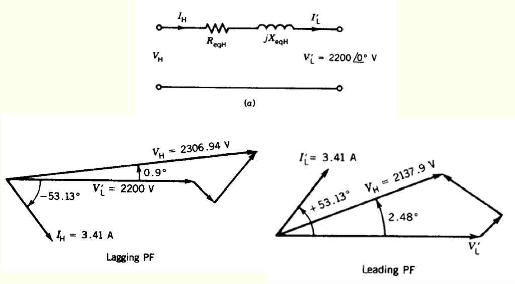
36 Voltage Regulation Consider Fig..14a, where the transformer is represented by a series impedance Zeq. If a load is not applied to the transformer (i.e., open-circuit or no-load condition) the load terminal voltage is If the load switch is now closed and the load is connected to the transformer secondary, the load terminal voltage is
37 To reduce the magnitude of the voltage change, the transformer should be designed for a low value of the internal impedance Zeq. Voltage regulation is defined as the change in magnitude of the secondary voltage as the load current changes from the no-load to the loaded condition. Voltage regulation V NL V L V L For the equivalent circuit referred to the primary, Voltage regulation The load is normally taken as the rated voltage, therefore, V ' NL ' V L V ' L V ' L V ' rated
38 From the approximate equivalent circuit referred to the primary, V V I R ' ' ' 1 eq1 eq1 If the load is thrown off, V 1 will appear as V, hence, V NL ' V1 ji X So, Voltage regulation ( in percent) V 1 V V ' rated ' rated 100%
39


40 The voltage regulation depends on the power factor of the load. This can be appreciated from the phasor diagram of the voltages. The phasor diagram is drawn in Figure. The locus of V1 is a circle of radius. The magnitude of V1 will be maximum if the phasor is in phase with. That is, Therefore the maximum voltage regulation occurs: if the power factor angle of the load is the same as the transformer equivalent impedance angle and the load power factor is lagging.
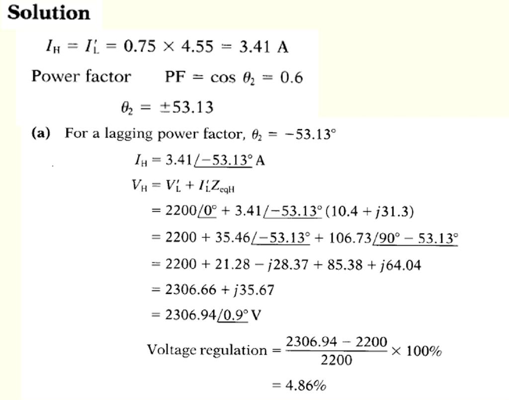
41 Example 3 Consider the transformer in example. Determine the voltage regulation in percent for the following load conditions: a) 75% full load, 0.6 power factor lagging. [4.86%] b) 75% full load, 0.6 power factor leading. [-.8%]
42
43 The meaning of 4.86% voltage regulation is that if the load is thrown off, the load terminal voltage will rise from 0 to volts. In other words, when the 75% full load at 0.6 lagging power factor is connected to the load terminals of the transformer, the voltage drops from to 0 volts.
44 Note that the voltage regulation for this leading power factor load is negative. This means that if the load is thrown off, the load terminal voltage will decrease from 0 to volts. To put it differently, if the leading power factor load is connected to the load terminals, the voltage will increase from to 0 volts.
45 Efficiency Losses in transformers are small. Because the transformer is a static device, there are no rotational losses such as windage and friction losses in a rotating machine. In a well-designed transformer, the efficiency can be as high as 99%. The efficiency is out in The losses in the transformer are the core loss (P c ) and copper loss (P cu ). Therefore, P P P out P P P out out c Pout losses P cu P in losses P out
46 The copper losses can be determined as: The core loss (P c ) is almost constant and can be obtained fro the no-load test of a transformer, eq eq cu R I R I R I R I P cos cos cos eq c out R I P I V I V I V P

47 Maximum Efficiency For constant values of the terminal voltage V and load power factor angle, the maximum efficiency occurs when The condition for maximum efficiency is obtained when P I c eq That is core loss = copper loss. For full load condition, P I Maximum efficiency for any power factor: R cu, FL, FL eq R V VI cos I cos P c


48 For constant values of the terminal voltage V and load current I, the maximum efficiency occurs when If this condition is applied to efficiency equation, the condition for maximum efficiency is that is, load power factor = 1
49 Therefore, maximum efficiency in a transformer occurs when the load power factor is unity (i.e., resistive load) and load current is such that copper loss equals core loss.
50 ALL-DAY (OR ENERGY) EFFICIENCY Such transformers are called power transformers, and they are usually designed for maximum efficiency occurring near the rated output. A transformer connected to the utility that supplies power to your house and the locality is called a distribution transformer. Such transformers are connected to the power system for 4 hours a day and operate well below the rated power output for most of the time. It is therefore desirable to design a distribution transformer for maximum efficiency occurring at the average output power. A figure of merit that will be more appropriate to represent the efficiency performance of a distribution transformer is the "allday" or "energy" efficiency of the transformer.
51 This is defined as follows: If the load cycle of the transformer is known, the all-day efficiency can be determined.
52 Example 4 For the transformer in example, determine: a) Efficiency at 75% rated output and 0.6 PF. [95.3%] b) The value of maximum efficiency. At what percent of full load does this maximum efficiency occur? [97.15%], [68.% full load]

53 a)
54 b)
55 Other Method From Example 4 From Equation
56 Example 5 A 50 kva, V transformer has a core loss Pc = 00 W at rated voltage and a copper loss Pcu = 500 W at full load. It has the following load cycle. Determine the all-day efficiency of the transformer.
57 AUTOTRANSFORMER This is a special connection of the transformer from which a variable ac voltage can be obtained at the secondary. A common winding as shown is mounted on a core and the secondary is taken from a tap on the winding. In contrast to the two-winding transformer discussed earlier, the primary and secondary of an autotransformer are physically connected. Since all the turns link the same flux in the transformer core
58 If the secondary tapping is replaced by a slider, the output voltage can be varied over the range 0 < V < V1. The ampere-turns provided by the upper half (i.e., by turns between points a and b) are: The ampere-turns provided by the lower half (i.e., by turns between points b and c) are: For ampere-turn balance, from Equations the voltages and currents are related by the same turns ratio as in a two-winding transformer.
Chapter 2-1 Transformers
 Principles of Electric Machines and Power Electronics Chapter 2-1 Transformers Third Edition P. C. Sen Transformer application 1: power transmission Ideal Transformer Assumptions: 1. Negligible winding
UNIVERSITY OF TECHNOLOGY By: Fadhil A. Hasan ELECTRICAL MACHINES
 UNIVERSITY OF TECHNOLOGY DEPARTMENT OF ELECTRICAL ENGINEERING Year: Second 2016-2017 By: Fadhil A. Hasan ELECTRICAL MACHINES І Module-II: AC Transformers o Single phase transformers o Three-phase transformers
Transformers. gpmacademics.weebly.com
 TRANSFORMERS Syllabus: Principles of operation, Constructional Details, Losses and efficiency, Regulation of Transformer, Testing: OC & SC test. TRANSFORMER: It is a static device which transfers electric
Transformer & Induction M/C
 UNIT- 2 SINGLE-PHASE TRANSFORMERS 1. Draw equivalent circuit of a single phase transformer referring the primary side quantities to secondary and explain? (July/Aug - 2012) (Dec 2012) (June/July 2014)
86 chapter 2 Transformers
 86 chapter 2 Transformers Wb 1.2x10 3 0 1/60 2/60 3/60 4/60 5/60 6/60 t (sec) 1.2x10 3 FIGURE P2.2 2.3 A single-phase transformer has 800 turns on the primary winding and 400 turns on the secondary winding.
148 Electric Machines
 148 Electric Machines 3.1 The emf per turn for a single-phase 2200/220- V, 50-Hz transformer is approximately 12 V. Calculate (a) the number of primary and secondary turns, and (b) the net cross-sectional
WELCOME TO THE LECTURE
 WLCOM TO TH LCTUR ON TRNFORMR Single Phase Transformer Three Phase Transformer Transformer transformer is a stationary electric machine which transfers electrical energy (power) from one voltage level
EEE3441 Electrical Machines Department of Electrical Engineering. Lecture. Basic Operating Principles of Transformers
 Department of Electrical Engineering Lecture Basic Operating Principles of Transformers In this Lecture Basic operating principles of following transformers are introduced Single-phase Transformers Three-phase
SECTION 4 TRANSFORMERS. Yilu (Ellen) Liu. Associate Professor Electrical Engineering Department Virginia Tech University
 Liu. Associate Professor Electrical Engineering Department Virginia Tech University") SECTION 4 TRANSFORMERS Yilu (Ellen) Liu Associate Professor Electrical Engineering Department Virginia Tech University Analysis of Transformer Turns Ratio......................... 4.2 Analysis of a Step-Up
SECTION 4 TRANSFORMERS Yilu (Ellen) Liu Associate Professor Electrical Engineering Department Virginia Tech University Analysis of Transformer Turns Ratio......................... 4.2 Analysis of a Step-Up
Spring 2000 EE361: MIDTERM EXAM 1
 NAME: STUDENT NUMBER: Spring 2000 EE361: MIDTERM EXAM 1 This exam is open book and closed notes. Assume f=60 hz and use the constant µ o =4π 10-7 wherever necessary. Be sure to show all work clearly. 1.
TRANSFORMERS PART A. 2. What is the turns ratio and transformer ratio of transformer? Turns ratio = N2/ N1 Transformer = E2/E1 = I1/ I2 =K
 UNIT II TRANSFORMERS PART A 1. Define a transformer? A transformer is a static device which changes the alternating voltage from one level to another. 2. What is the turns ratio and transformer ratio of
Practical Transformer on Load
 Practical Transformer on Load We now consider the deviations from the last two ideality conditions : 1. The resistance of its windings is zero. 2. There is no leakage flux. The effects of these deviations
Module 7. Transformer. Version 2 EE IIT, Kharagpur
 Module 7 Transformer Lesson 3 Ideal Transformer Contents 3 Ideal Transformer (Lesson: 3) 4 3. Goals of the lesson 4 3. Introduction.. 5 3.. Principle of operation.. 5 3.3 Ideal Transformer.. 6 3.3. Core
Walchand Institute of Technology. Basic Electrical and Electronics Engineering. Transformer
 Walchand Institute of Technology Basic Electrical and Electronics Engineering Transformer 1. What is transformer? explain working principle of transformer. Electrical power transformer is a static device
Transformers. Dr. Gamal Sowilam
 Transformers Dr. Gamal Sowilam OBJECTIVES Become familiar with the flux linkages that exist between the coils of a transformer and how the voltages across the primary and secondary are established. Understand
INSTITUTE OF AERONAUTICAL ENGINEERING (Autonomous) Dundigal, Hyderabad
 Dundigal, Hyderabad") INSTITUTE OF AERONAUTICAL ENGINEERING (Autonomous) Dundigal, Hyderabad - 00 0 ELECTRICAL AND ELECTRONICS ENGINEERING QUESTION BANK Course Name Course Code Class Branch : ELECRICAL MACHINES - II : A0 :
INSTITUTE OF AERONAUTICAL ENGINEERING (Autonomous) Dundigal, Hyderabad - 00 0 ELECTRICAL AND ELECTRONICS ENGINEERING QUESTION BANK Course Name Course Code Class Branch : ELECRICAL MACHINES - II : A0 :
INSTITUTE OF AERONAUTICAL ENGINEERING (Autonomous) Dundigal, Hyderabad ELECTRICAL AND ELECTRONICS ENGINEERING
 Dundigal, Hyderabad ELECTRICAL AND ELECTRONICS ENGINEERING") Course Name Course Code Class Branch INSTITUTE OF AERONAUTICAL ENGINEERING (Autonomous) Dundigal, Hyderabad - 500 043 ELECTRICAL AND ELECTRONICS ENGINEERING QUESTION BANK : ELECRICAL MACHINES I : A40212
Course Name Course Code Class Branch INSTITUTE OF AERONAUTICAL ENGINEERING (Autonomous) Dundigal, Hyderabad - 500 043 ELECTRICAL AND ELECTRONICS ENGINEERING QUESTION BANK : ELECRICAL MACHINES I : A40212
PROBLEMS on Transformers
 PROBLEMS on Transformers (A) Simple Problems 1. A single-phase, 250-kVA, 11-kV/415-V, 50-Hz transformer has 80 turns on the secondary. Calculate (a) the approximate values of the primary and secondary
Aligarh College of Engineering & Technology (College Code: 109) Affiliated to UPTU, Approved by AICTE Electrical Engg.
 Affiliated to UPTU, Approved by AICTE Electrical Engg.") Aligarh College of Engineering & Technology (College Code: 19) Electrical Engg. (EE-11/21) Unit-I DC Network Theory 1. Distinguish the following terms: (a) Active and passive elements (b) Linearity and
Aligarh College of Engineering & Technology (College Code: 19) Electrical Engg. (EE-11/21) Unit-I DC Network Theory 1. Distinguish the following terms: (a) Active and passive elements (b) Linearity and
Module 7. Transformer. Version 2 EE IIT, Kharagpur
 Module 7 Transformer Lesson 28 Problem solving on Transformers Contents 28 Problem solving on Transformer (Lesson-28) 4 28.1 Introduction. 4 28.2 Problems on 2 winding single phase transformers. 4 28.3
3. What is hysteresis loss? Also mention a method to minimize the loss. (N-11, N-12)
") DHANALAKSHMI COLLEGE OF ENGINEERING, CHENNAI DEPARTMENT OF ELECTRICAL AND ELECTRONICS ENGINEERING EE 6401 ELECTRICAL MACHINES I UNIT I : MAGNETIC CIRCUITS AND MAGNETIC MATERIALS Part A (2 Marks) 1. List
DHANALAKSHMI COLLEGE OF ENGINEERING, CHENNAI DEPARTMENT OF ELECTRICAL AND ELECTRONICS ENGINEERING EE 6401 ELECTRICAL MACHINES I UNIT I : MAGNETIC CIRCUITS AND MAGNETIC MATERIALS Part A (2 Marks) 1. List
VALLIAMMAI ENGINEERING COLLEGE
 VALLIAMMAI ENGINEERING COLLEGE SRM Nagar, Kattankulathur 603 203 DEPARTMENT OF ELECTRONICS AND INSTRUMENTATION ENGINEERING QUESTION BANK IV SEMESTER EI6402 ELECTRICAL MACHINES Regulation 2013 Academic
EE 340 Power Transformers
 EE 340 Power Transformers Preliminary considerations A transformer is a device that converts one AC voltage to another AC voltage at the same frequency. It consists of one or more coil(s) of wire wrapped
INSTITUTE OF AERONAUTICAL ENGINEERING (Autonomous) Dundigal, Hyderabad
 Dundigal, Hyderabad") INSTITUTE OF AERONAUTICAL ENGINEERING (Autonomous) Dundigal, Hyderabad - 00 03 ELECTRICAL AND ELECTRONICS ENGINEERING ASSIGNMENT Course Name : ELECRICAL MACHINES - II Course Code : A0 Class : II B.TECH-II
INSTITUTE OF AERONAUTICAL ENGINEERING (Autonomous) Dundigal, Hyderabad - 00 03 ELECTRICAL AND ELECTRONICS ENGINEERING ASSIGNMENT Course Name : ELECRICAL MACHINES - II Course Code : A0 Class : II B.TECH-II
Transformers 21.1 INTRODUCTION 21.2 MUTUAL INDUCTANCE
 21 Transformers 21.1 INTRODUCTION Chapter 12 discussed the self-inductance of a coil. We shall now examine the mutual inductance that exists between coils of the same or different dimensions. Mutual inductance
AUTO-TRANSFORMER. This is having only one winding; part of this winding is common to both primary and secondary.
 AUTO-TRANSFORMER This is having only one winding; part of this winding is common to both primary and secondary. In 2-winding transformer both primary and secondary windings are electrically isolated, but
CHAPTER 2. Basic Concepts, Three-Phase Review, and Per Unit
 CHAPTER 2 Basic Concepts, Three-Phase Review, and Per Unit 1 AC power versus DC power DC system: - Power delivered to the load does not fluctuate. - If the transmission line is long power is lost in the
SHRI RAMSWAROOP MEMORIAL COLLEGE OF ENGG. & MANAGEMENT B.Tech. [SEM I (EE, EN, EC, CE)] QUIZ TEST-3 (Session: ) Time: 1 Hour ELECTRICAL ENGINEE
![SHRI RAMSWAROOP MEMORIAL COLLEGE OF ENGG. & MANAGEMENT B.Tech. [SEM I (EE, EN, EC, CE)] QUIZ TEST-3 (Session: ) Time: 1 Hour ELECTRICAL ENGINEE](/thumbs/94/118213481.jpg "SHRI RAMSWAROOP MEMORIAL COLLEGE OF ENGG. & MANAGEMENT B.Tech. [SEM I (EE, EN, EC, CE)] QUIZ TEST-3 (Session: ) Time: 1 Hour ELECTRICAL ENGINEE") SHRI RAMSWAROOP MEMORIAL COLLEGE OF ENGG. & MANAGEMENT B.Tech. [SEM I (EE, EN, EC, CE)] QUIZ TEST-3 (Session: 2014-15) Time: 1 Hour ELECTRICAL ENGINEERING Max. Marks: 30 (NEE-101) Roll No. Academic/26
SHRI RAMSWAROOP MEMORIAL COLLEGE OF ENGG. & MANAGEMENT B.Tech. [SEM I (EE, EN, EC, CE)] QUIZ TEST-3 (Session: 2014-15) Time: 1 Hour ELECTRICAL ENGINEERING Max. Marks: 30 (NEE-101) Roll No. Academic/26
EE2022 Electrical Energy Systems
 EE0 Electrical Energy Systems Lecture : Transformer and Per Unit Analysis 7-0-0 Panida Jirutitijaroen Department of Electrical and Computer Engineering /9/0 EE0: Transformer and Per Unit Analysis by P.
By Gill ( ) PDF created with FinePrint pdffactory trial version
 PDF created with FinePrint pdffactory trial version") By Gill (www.angelfire.com/al4/gill ) 1 Introduction One of the main reasons of adopting a.c. system instead of d.c. for generation, transmission and distribution of electrical power is that alternatin
By Gill (www.angelfire.com/al4/gill ) 1 Introduction One of the main reasons of adopting a.c. system instead of d.c. for generation, transmission and distribution of electrical power is that alternatin
Reg. No. : BASIC ELECTRICAL TECHNOLOGY (ELE 101)
") Department of Electrical and Electronics Engineering Reg. No. : MNIPL INSTITUTE OF TECHNOLOGY, MNIPL ( Constituent Institute of Manipal University, Manipal) FIRST SEMESTER B.E. DEGREE MKEUP EXMINTION (REVISED
Department of Electrical and Electronics Engineering Reg. No. : MNIPL INSTITUTE OF TECHNOLOGY, MNIPL ( Constituent Institute of Manipal University, Manipal) FIRST SEMESTER B.E. DEGREE MKEUP EXMINTION (REVISED
Hours / 100 Marks Seat No.
 17415 15162 3 Hours / 100 Seat No. Instructions (1) All Questions are Compulsory. (2) Answer each next main Question on a new page. (3) Illustrate your answers with neat sketches wherever necessary. (4)
El-Hawary, M.E. The Transformer Electrical Energy Systems. Series Ed. Leo Grigsby Boca Raton: CRC Press LLC, 2000
 El-Hawary, M.E. The Transformer Electrical Energy Systems. Series Ed. Leo Grigsby Boca Raton: CRC Press LLC, 000 97 Chapter 4 THE TRANSFORMER 4. NTRODUCTON The transformer is a valuable apparatus in electrical
MAHARASHTRA STATE BOARD OF TECHNICAL EDUCATION
 Important Instructions to examiners: 1) The answers should be examined by key words and not as word-to-word as given in the model answer scheme. 2) The model answer and the answer written by candidate
ELG2336 Introduction to Electric Machines
 ELG2336 Introduction to Electric Machines Magnetic Circuits DC Machine Shunt: Speed control Series: High torque Permanent magnet: Efficient AC Machine Synchronous: Constant speed Induction machine: Cheap
INSTITUTE OF AERONAUTICAL ENGINEERING (Autonomous) Dundigal, Hyderabad
 Dundigal, Hyderabad") INSTITUTE OF AERONAUTICAL ENGINEERING (Autonomous) Dundigal, Hyderabad -00 03 ELECTRCIAL AND ELECTRONICS ENGINEERING TUTORIAL QUESTION BANK Course Name Course Code Class Branch : DC MACHINES AND TRANSFORMERS
INSTITUTE OF AERONAUTICAL ENGINEERING (Autonomous) Dundigal, Hyderabad -00 03 ELECTRCIAL AND ELECTRONICS ENGINEERING TUTORIAL QUESTION BANK Course Name Course Code Class Branch : DC MACHINES AND TRANSFORMERS
SHRI RAMSWAROOP MEMORIAL COLLEGE OF ENGG. & MANAGEMENT
 SHRI RAMSWAROOP MEMORIAL COLLEGE OF ENGG. & MANAGEMENT B.Tech. [SEM I (CE,EC,EE,EN)] QUIZ TEST-3 (Session: 2012-13) Time: 1 Hour ELECTRICAL ENGINEERING Max. Marks: 30 (EEE-101) Roll No. Academic/26 Refer/WI/ACAD/18
Module 1. Introduction. Version 2 EE IIT, Kharagpur
 Module 1 Introduction Lesson 1 Introducing the Course on Basic Electrical Contents 1 Introducing the course (Lesson-1) 4 Introduction... 4 Module-1 Introduction... 4 Module-2 D.C. circuits.. 4 Module-3
Unit 3 Magnetism...21 Introduction The Natural Magnet Magnetic Polarities Magnetic Compass...21
 Chapter 1 Electrical Fundamentals Unit 1 Matter...3 Introduction...3 1.1 Matter...3 1.2 Atomic Theory...3 1.3 Law of Electrical Charges...4 1.4 Law of Atomic Charges...4 Negative Atomic Charge...4 Positive
Electrical Machines (EE-343) For TE (ELECTRICAL)
 For TE (ELECTRICAL)") PRACTICALWORKBOOK Electrical Machines (EE-343) For TE (ELECTRICAL) Name: Roll Number: Year: Batch: Section: Semester: Department: N.E.D University of Engineering &Technology, Karachi Electrical Machines
PRACTICALWORKBOOK Electrical Machines (EE-343) For TE (ELECTRICAL) Name: Roll Number: Year: Batch: Section: Semester: Department: N.E.D University of Engineering &Technology, Karachi Electrical Machines
Preface...x Chapter 1 Electrical Fundamentals
 Preface...x Chapter 1 Electrical Fundamentals Unit 1 Matter...3 Introduction...3 1.1 Matter...3 1.2 Atomic Theory...3 1.3 Law of Electrical Charges...4 1.4 Law of Atomic Charges...5 Negative Atomic Charge...5
The power transformer
 ELEC0014 - Introduction to power and energy systems The power transformer Thierry Van Cutsem t.vancutsem@ulg.ac.be www.montefiore.ulg.ac.be/~vct November 2017 1 / 35 Power transformers are used: to transmit
3.1.Introduction. Synchronous Machines
 3.1.Introduction Synchronous Machines A synchronous machine is an ac rotating machine whose speed under steady state condition is proportional to the frequency of the current in its armature. The magnetic
Chapter 7. Copyright The McGraw-Hill Companies, Inc. Permission required for reproduction or display.
 Chapter 7 Copyright The McGraw-Hill Companies, Inc. Permission required for reproduction or display. Learning Objectives 1. Understand the meaning of instantaneous and average power, master AC power notation,
 VIDYARTHIPLUS - ANNA UNIVERSITY ONLINE STUDENTS COMMUNITY UNIT 1 DC MACHINES PART A 1. State Faraday s law of Electro magnetic induction and Lenz law. 2. Mention the following functions in DC Machine (i)
TRANSFORMER THEORY. Mutual Induction
 Transformers Transformers are used extensively for AC power transmissions and for various control and indication circuits. Knowledge of the basic theory of how these components operate is necessary to
Chapter 33. Alternating Current Circuits
 Chapter 33 Alternating Current Circuits C HAP T E O UTLI N E 33 1 AC Sources 33 2 esistors in an AC Circuit 33 3 Inductors in an AC Circuit 33 4 Capacitors in an AC Circuit 33 5 The L Series Circuit 33
ECG 741 Power Distribution Transformers. Y. Baghzouz Spring 2014
 ECG 741 Power Distribution Transformers Y. Baghzouz Spring 2014 Preliminary Considerations A transformer is a device that converts one AC voltage to another AC voltage at the same frequency. The windings
Chapter 33. Alternating Current Circuits
 Chapter 33 Alternating Current Circuits Alternating Current Circuits Electrical appliances in the house use alternating current (AC) circuits. If an AC source applies an alternating voltage to a series
CHAPTER 9. Sinusoidal Steady-State Analysis
 CHAPTER 9 Sinusoidal Steady-State Analysis 9.1 The Sinusoidal Source A sinusoidal voltage source (independent or dependent) produces a voltage that varies sinusoidally with time. A sinusoidal current source
AC Power Instructor Notes
 Chapter 7: AC Power Instructor Notes Chapter 7 surveys important aspects of electric power. Coverage of Chapter 7 can take place immediately following Chapter 4, or as part of a later course on energy
Electrical Machines I : Transformers
 UNIT TRANSFORMERS PART A (Q&A) 1. What is step down transformer? The transformer used to step down the voltage from primary to secondary is called as step down transformer. (Ex: /11).. Draw the noload
EQUIVALENT CIRCUIT OF A SINGLE-PHASE TRANSFORMER
 Electrical Machines Lab Experiment-No. One Date: 15-11-2016 EQUIVALENT CIRCUIT OF A SINGLE-PHASE TRANSFORMER Aim: The determination of electrical equivalent circuit parameters of a single phase power transformer
ELECTRICAL ENGINEERING ESE TOPIC WISE OBJECTIVE SOLVED PAPER-II
 ELECTRICAL ENGINEERING ESE TOPIC WISE OBJECTIVE SOLVED PAPER-II From (1992 2017) Office : F-126, (Lower Basement), Katwaria Sarai, New Delhi-110016 Phone : 011-26522064 Mobile : 8130909220, 9711853908
CHAPTER 4. Distribution Transformers
 CHAPTER 4 Distribution Transformers Introduction A transformer is an electrical device that transfers energy from one circuit to another purely by magnetic coupling. Relative motion of the parts of the
SYNCHRONOUS MACHINES
 SYNCHRONOUS MACHINES The geometry of a synchronous machine is quite similar to that of the induction machine. The stator core and windings of a three-phase synchronous machine are practically identical
Physics for Scientists & Engineers 2 2 = 1 LC. Review ( ) Review (2) Review (3) e! Rt. cos "t + # ( ) q = q max. Spring Semester 2005 Lecture 30 U E
 Review (2) Review (3) e! Rt. cos t + # ( ) q = q max. Spring Semester 2005 Lecture 30 U E") Review hysics for Scientists & Engineers Spring Semester 005 Lecture 30! If we have a single loop RLC circuit, the charge in the circuit as a function of time is given by! Where q = q max e! Rt L cos "t
Review hysics for Scientists & Engineers Spring Semester 005 Lecture 30! If we have a single loop RLC circuit, the charge in the circuit as a function of time is given by! Where q = q max e! Rt L cos "t
Table of Contents. Table of Figures. Table of Tables
 Abstract The aim of this report is to investigate and test a transformer and check if it is good to use by doing the following tests continuity test, insulation test, polarity test, open circuit test,
UNIT 4 TRANSFORMER 4.1 INTRODUCTION. Structure. 4.1 Introduction. 4.2 Basics of Transformer. 4.3 Equivalent Circuit of Transformer
 UT 4 TRASFORMR Transformer Structure 4. ntroduction Objectives 4. Basics of Transformer 4.. ntroduction 4.. MF quation of a Transformer 4..3 Construction 4.3 quivalent Circuit of Transformer 4.3. quivalent
MAHARASHTRA STATE BOARD OF TECHNICAL EDUCATION
 Important Instructions to examiners: 1) The answers should be examined by key words and not as word-to-word as given in the model answer scheme. 2) The model answer and the answer written by candidate
QUESTION BANK ETE (17331) CM/IF. Chapter1: DC Circuits
 CM/IF. Chapter1: DC Circuits") QUESTION BANK ETE (17331) CM/IF Chapter1: DC Circuits Q1. State & explain Ohms law. Also explain concept of series & parallel circuit with the help of diagram. 3M Q2. Find the value of resistor in fig.
QUESTION BANK ETE (17331) CM/IF Chapter1: DC Circuits Q1. State & explain Ohms law. Also explain concept of series & parallel circuit with the help of diagram. 3M Q2. Find the value of resistor in fig.
13. Magnetically Coupled Circuits
 13. Magnetically Coupled Circuits The change in the current flowing through an inductor induces (creates) a voltage in the conductor itself (self-inductance) and in any nearby conductors (mutual inductance)
PART A. 1. List the types of DC Motors. Give any difference between them. BTL 1 Remembering
 UNIT I DC MACHINES Three phase circuits, a review. Construction of DC machines Theory of operation of DC generators Characteristics of DC generators Operating principle of DC motors Types of DC motors
Generalized Theory Of Electrical Machines
 Essentials of Rotating Electrical Machines Generalized Theory Of Electrical Machines All electrical machines are variations on a common set of fundamental principles, which apply alike to dc and ac types,
ELECTROMAGNETIC INDUCTION AND ALTERNATING CURRENT (Assignment)
") ELECTROMAGNETIC INDUCTION AND ALTERNATING CURRENT (Assignment) 1. In an A.C. circuit A ; the current leads the voltage by 30 0 and in circuit B, the current lags behind the voltage by 30 0. What is the
ELECTROMAGNETIC INDUCTION AND ALTERNATING CURRENT (Assignment) 1. In an A.C. circuit A ; the current leads the voltage by 30 0 and in circuit B, the current lags behind the voltage by 30 0. What is the
ESO 210 Introduction to Electrical Engineering
 ESO 210 Introduction to Electrical Engineering Lecture-19 Magnetic Circuits and Introduction to Transformers 2 SERIES CONNECTION OF MUTUALLY COUPLED COILS A mutual term will alter the total inductance
Manuals. Basic Electrical Engineering BE-104
 Manuals Basic Electrical Engineering BE-104 S.NO. EXPERIMENT NAME DATE 1 Measurement of power & power factor in a single phase AC circuit using three Ammeter Method 2 Measurement of active & reactive power
An induced emf is the negative of a changing magnetic field. Similarly, a self-induced emf would be found by
 This is a study guide for Exam 4. You are expected to understand and be able to answer mathematical questions on the following topics. Chapter 32 Self-Induction and Induction While a battery creates an
TRANSFORMER OPERATION
 Chapter 3 TRANSFORMER OPERATION 1 A transformer is a static device (no moving parts) used to transfer energy from one AC circuit to another. This transfer of energy may involve an increase or decrease
REV NO EXPERIMENT NO 1 AIM: To perform open and short circuit tests on 1-phase transformer and to calculate efficiency. Apparatus required:
 KARNAL INSTITUTE OF TECHNOLOGY & MANAGEMENT KUNJPURA, KARNAL LAB MANUAL OF ------- SUBJECT CODE DATE OF ISSUE: SEMESTER: BRANCH: REV NO EXPERIMENT NO 1 AIM: To perform open and short circuit tests on 1-phase
Transformers. Department of Physics & Astronomy Texas Christian University, Fort Worth, TX. April 23, 2013
 Transformers Department of Physics & Astronomy Texas Christian University, Fort Worth, TX April 23, 2013 1 Introduction In the early nineteenth century, Hans Christian Øersted discovered that a magnetic
APPLICATION NOTE - 018
 APPLICATION NOTE - 018 Power Transformers Background Power Transformers are used within an AC power distribution systems to increase or decrease the operating voltage to achieve the optimum transmission
INSTITUTE OF AERONAUTICAL ENGINEERING (Autonomous) Dundigal, Hyderabad
 Dundigal, Hyderabad") I INSTITUTE OF AERONAUTICAL ENGINEERING (Autonomous) Dundigal, Hyderabad-500043 CIVIL ENGINEERING TUTORIAL QUESTION BANK Course Name : BASIC ELECTRICAL AND ELECTRONICS ENGINEERING Course Code : AEE018
I INSTITUTE OF AERONAUTICAL ENGINEERING (Autonomous) Dundigal, Hyderabad-500043 CIVIL ENGINEERING TUTORIAL QUESTION BANK Course Name : BASIC ELECTRICAL AND ELECTRONICS ENGINEERING Course Code : AEE018
EN Assignment No.1 - TRANSFORMERS
 EN-06 - Assignment No.1 - TRANSFORMERS Date : 13 th Jan 01 Q1) A 0kVA 00/0 Volts, 60Hz, single phase transformer is found to have the following equivalent circuit parameter referred to the high potential
Experiment No. Experiments for First Year Electrical Engg Lab
 Experiment No im: To determine Regulation and Efficiency of a single phase transformer using open circuit (O.C.) and short circuit (S.C.) tests pparatus: - Single phase transformer Single phase dimmer
Code No: R Set No. 1
 Code No: R05220204 Set No. 1 II B.Tech II Semester Supplimentary Examinations, Aug/Sep 2007 ELECTRICAL MACHINES-II (Electrical & Electronic Engineering) Time: 3 hours Max Marks: 80 Answer any FIVE Questions
1. If the flux associated with a coil varies at the rate of 1 weber/min,the induced emf is
 1. f the flux associated with a coil varies at the rate of 1 weber/min,the induced emf is 1 1. 1V 2. V 60 3. 60V 4. Zero 2. Lenz s law is the consequence of the law of conservation of 1. Charge 2. Mass
APPENDIX 4 TYPICAL LAYOUT, VALUES AND CONSTANTS
 109 APPENDIX 4 TYPICAL LAYOUT, VALUES AND CONSTANTS TYPICAL LAYOUT The purpose of a transformer is to transfer energy from the input to the output through the magnetic field. The layout of a partial typical
1 K Hinds 2012 TRANSFORMERS
 1 K Hinds 2012 TRANSFORMERS A transformer changes electrical energy of a given voltage into electrical energy at a different voltage level. It consists of two coils which are not electrically connected,
TRANSFORMERS INTRODUCTION
 Tyco Electronics Corporation Crompton Instruments 1610 Cobb International Parkway, Unit #4 Kennesaw, GA 30152 Tel. 770-425-8903 Fax. 770-423-7194 TRANSFORMERS INTRODUCTION A transformer is a device that
EE 221 Circuits II. Chapter 13 Magnetically Coupled Circuits
 EE Circuits II Chapter 3 Magnetically Coupled Circuits Magnetically Coupled Circuits 3. What is a transformer? 3. Mutual Inductance 3.3 Energy in a Coupled Circuit 3.4 inear Transformers 3.5 Ideal Transformers
ELECTRICAL MEASUREMENTS
 R10 Set No: 1 1. a) Derive the expression for torque equation for a moving iron attraction type instrument and comment up on the nature of scale [8] b) Define the terms current sensitivity, voltage sensitivity
1. THREE-PHASE TRANSFORMER. SHORT CIRCUIT TEST
 1. THREE-PHASE TRANSFORMER. SHORT CIRCUIT TEST 1.1 INTRODUCTION. DESCRIPTION OF THE EXPERIMENT The short-circuit test consists of measuring the input quantities of the transformer when its secondary winding
1. (a) Determine the value of Resistance R and current in each branch when the total current taken by the curcuit in figure 1a is 6 Amps.
 Determine the value of Resistance R and current in each branch when the total current taken by the curcuit in figure 1a is 6 Amps.") Code No: 07A3EC01 Set No. 1 II B.Tech I Semester Regular Examinations, November 2008 ELECTRICAL AND ELECTRONICS ENGINEERING ( Common to Civil Engineering, Mechanical Engineering, Mechatronics, Production
Code No: 07A3EC01 Set No. 1 II B.Tech I Semester Regular Examinations, November 2008 ELECTRICAL AND ELECTRONICS ENGINEERING ( Common to Civil Engineering, Mechanical Engineering, Mechatronics, Production
Review: Lecture 9. Instantaneous and Average Power. Effective or RMS Value. Apparent Power and Power Factor. Complex Power. Conservation of AC Power
 Review: Lecture 9 Instantaneous and Average Power p( t) VmI m cos ( v i ) VmI m cos ( t v i ) Maximum Average Power Transfer Z L R L jx Effective or RMS Value I rms I m L R P * TH Apparent Power and Power
ECE 241L Fundamentals of Electrical Engineering. Experiment 8 A-C Transformer, Magnetization & Hysteresis
 ECE 241L Fundamentals of Electrical Engineering Experiment 8 A-C Transformer, Magnetization & Hysteresis A. Objectives: I. Measure leakage inductance and resistance loss II. Measure magnetization inductance
Department of Electrical and Computer Engineering Lab 6: Transformers
 ESE Electronics Laboratory A Department of Electrical and Computer Engineering 0 Lab 6: Transformers. Objectives ) Measure the frequency response of the transformer. ) Determine the input impedance of
Experiment 45. Three-Phase Circuits. G 1. a. Using your Power Supply and AC Voltmeter connect the circuit shown OBJECTIVE
 Experiment 45 Three-Phase Circuits OBJECTIVE To study the relationship between voltage and current in three-phase circuits. To learn how to make delta and wye connections. To calculate the power in three-phase
Dhanalakshmi Srinivasan Institute of Technology, Samayapuram, Trichy. Cycle 2 EE6512 Electrical Machines II Lab Manual
 Cycle 2 EE652 Electrical Machines II Lab Manual CIRCUIT DIAGRAM FOR SLIP TEST 80V DC SUPPLY 350Ω, 2 A 3 Point Starter L F A NAME PLATE DETAILS: 3Ф alternator DC shunt motor FUSE RATING: Volts: Volts: 25%
Alternating current circuits- Series RLC circuits
 FISI30 Física Universitaria II Professor J.. ersosimo hapter 8 Alternating current circuits- Series circuits 8- Introduction A loop rotated in a magnetic field produces a sinusoidal voltage and current.
Experiment 3 Single Phase Transformer (II)
") Objectives To determine the polarity of single phase transformer windings. To determine the internal resistance of single phase transformer windings. To determine the efficiency and voltage regulation
Objectives To determine the polarity of single phase transformer windings. To determine the internal resistance of single phase transformer windings. To determine the efficiency and voltage regulation
ISSN: X Impact factor: (Volume 3, Issue 6) Available online at Modeling and Analysis of Transformer
 Available online at Modeling and Analysis of Transformer") ISSN: 2454-132X Impact factor: 4.295 (Volume 3, Issue 6) Available online at www.ijariit.com Modeling and Analysis of Transformer Divyapradeepa.T Department of Electrical and Electronics, Rajalakshmi Engineering
ISSN: 2454-132X Impact factor: 4.295 (Volume 3, Issue 6) Available online at www.ijariit.com Modeling and Analysis of Transformer Divyapradeepa.T Department of Electrical and Electronics, Rajalakshmi Engineering
Power. Power is the rate of using energy in joules per second 1 joule per second Is 1 Watt
 3 phase Power All we need electricity for is as a source of transport for energy. We can connect to a battery, which is a source of stored energy. Or we can plug into and electric socket at home or in
13 th Asian Physics Olympiad India Experimental Competition Wednesday, 2 nd May 2012
 13 th Asian Physics Olympiad India Experimental Competition Wednesday, nd May 01 Please first read the following instructions carefully: 1. The time available is ½ hours for each of the two experimental
Open Circuit (OC) and Short Circuit (SC) Tests on Single Phase Transformer
 and Short Circuit (SC) Tests on Single Phase Transformer") Open Circuit (OC) and Short Circuit (SC) Tests on Single Phase Transformer 1 Aim To obtain the equivalent circuit parameters from OC and SC tests, and to estimate efficiency & regulation at various loads.
Open Circuit (OC) and Short Circuit (SC) Tests on Single Phase Transformer 1 Aim To obtain the equivalent circuit parameters from OC and SC tests, and to estimate efficiency & regulation at various loads.
UNIT II MEASUREMENT OF POWER & ENERGY
 UNIT II MEASUREMENT OF POWER & ENERGY Dynamometer type wattmeter works on a very simple principle which is stated as "when any current carrying conductor is placed inside a magnetic field, it experiences
Electromagnetic Oscillations and Currents. March 23, 2014 Chapter 30 1
 Electromagnetic Oscillations and Currents March 23, 2014 Chapter 30 1 Driven LC Circuit! The voltage V can be thought of as the projection of the vertical axis of the phasor V m representing the time-varying
INSTITUTE OF AERONAUTICAL ENGINEERING
 POWER POINT PRESENTATION ON ELECTRICAL MACHINES - II 016-017 II B. Tech II semester (JNTUH-R15) Mr. K DEVENDER REDDY, Assistant Professor ELECTRICAL AND ELECTRONICS ENGINEERING INSTITUTE OF AERONAUTICAL
Engineering Science OUTCOME 4 - TUTORIAL 3 CONTENTS. 1. Transformers
 Unit : Unit code: QCF Level: 4 Credit value: 5 SYLLABUS Engineering Science L/60/404 OUTCOME 4 - TUTOIAL 3 Be able to apply single phase AC theory to solve electrical and electronic engineering problems
Chapter 2: Transformers
 Chapter 2: Transformers 2-1. The secondary winding of a transformer has a terminal voltage of v s (t) = 282.8 sin 377t V. The turns ratio of the transformer is 100:200 (a = 0.50). If the secondary current