EE 340 Power Transformers
|
|
|
- Amelia Peters
- 5 years ago
- Views:
Transcription

1 EE 340 Power Transformers
 of wire wrapped around a common ferromagnetic core.")
2 Preliminary considerations A transformer is a device that converts one AC voltage to another AC voltage at the same frequency. It consists of one or more coil(s) of wire wrapped around a common ferromagnetic core.


3 Common construction: Shell Form The windings are wrapped around the center leg of a laminated core. The windings are wrapped on top of each other to decrease flux leakage.
4 Ideal transformer An ideal transformer (unlike the real one) can be characterized as follows: 1.The core has no hysteresis nor eddy currents. 2.The magnetization curve is vertical with no saturation 3.The leakage flux in the core is zero. 4.The resistance of the windings is zero. Consider a lossless transformer with an input (primary) winding having N p turns and an output (secondary) winding of N s turns. The relationship between the voltage applied to the primary winding v p (t) and the voltage produced on the secondary winding v s (t) is vp() t N p a v () t N where a is the turn ratio of the transformer. s s
5 Ideal transformer The relationship between the primary i p (t) and secondary i s (t) currents is Phasor notation: ip() t 1 i () t a s p s a I I p s 1 a The phase angles of primary and secondary voltages are the same. The phase angles of primary and secondary currents are the same also. The ideal transformer changes magnitudes of voltages and currents but not their angles.
6 Ideal Transformer One winding s terminal is usually marked by a dot used to determine the polarity of voltages and currents. If the voltage is positive at the dotted end of the primary winding at some moment of time, the voltage at the dotted end of the secondary winding will also be positive at the same time instance. If the primary current flows into the dotted end of the primary winding, the secondary current will flow out of the dotted end of the secondary winding.
7 Power in an ideal transformer Assuming that p and s are the angles between voltages and currents on the primary and secondary windings respectively, the power supplied to the transformer by the primary circuit is: P I cos in p p p The power supplied to the output circuit is P I cos out s s s Since ideal transformers do not affect angles between voltages and currents: p s
8 Power in an ideal transformer Since for an ideal transformer the following holds: Therefore: P out p ; I ai a s s p p I cos ai cos I cos P a s s p p p in The output power of an ideal transformer equals to its input power to be expected since assumed no loss. Similarly, for reactive and apparent powers: Q I sin I sin Q out s s p p in Sout s Is pi p Sin

9 Impedance transformation The impedance is defined as a following ratio of phasors: ZL L IL A transformer changes voltages and currents and, therefore, an apparent impedance of the load that is given by ZL s Is The apparent impedance of the primary circuit is: ZL ' p Ip which is Z L ' a a I I a I p s 2 s 2 p s s a Z L
 If a 1:10 step up transformer and a 10:1 step down transformer are placed at the generator and the load ends of the transmission line respectively, what are the new load voltage and the new")
10 Analysis of circuits containing ideal transformers: Example Example 4.1: a) What is the voltage at the load? Calculate the transmission line losses? b) If a 1:10 step up transformer and a 10:1 step down transformer are placed at the generator and the load ends of the transmission line respectively, what are the new load voltage and the new transmission line losses? a) Without transformers: IG Iline Iload Z line j j Z load A load IloadZload (4 j3) P I R W 2 2 loss line line
 With transformers, we will eliminate")


11 Analysis of circuits containing ideal transformers: Example b) With transformers, we will eliminate transformer T 2 by referring the load over to the transmission line s voltage level. Eliminate transformer T 1 by referring the transmission line s voltage level to the source side, I G Z ' eq A
12 Analysis of circuits containing ideal transformers: Example Knowing transformers turn ratios, we can determine line and load currents: Iline a1ig A I load a2iline A Therefore, the load voltage is: load Iload Zload The losses in the line are: P I R W 2 2 loss line line
: p m Lp Flux leakage mutual flux leakage primary flux Similarly, for the secondary coil: s m Ls Leakage secondary")
13 Real transformer A portion of the flux produced in the primary coil passes through the secondary coil (mutual flux); the rest passes through the external medium (leakage flux): p m Lp Flux leakage mutual flux leakage primary flux Similarly, for the secondary coil: s m Ls Leakage secondary flux
14 Real transformer From the Faraday s law, the primary coil s voltage is: dp d d m Lp vp( t) N p N p N p ep ( t) elp ( t) dt dt dt The secondary coil s voltage is: ds dm dls vs ( t) Ns Ns Ns es ( t) els( t) dt dt dt The primary and secondary voltages due to the mutual flux are: dm dls ep() t N p es() t Ns dt dt Combining the last two equations: ep() t dm es() t N dt N p s
15 Real transformer Therefore: ep() t N e () t N s p s a That is, the ratio of the primary voltage to the secondary voltage both caused by the mutual flux is equal to the turns ratio of the transformer. The following approximation normally holds since the leakage flux is much smaller than the mutual flux;: vp() t N v () t N s p s a
16 Magnetization current in a real transformer Even when no load is connected to the secondary coil of the transformer, a current will flow in the primary coil. This current consists of: 1. The magnetization current i m is needed to produce the flux in the core; 2. The core-loss current i h+e corresponds to hysteresis and eddy current losses. Flux causing the magnetization current Typical magnetization curve


17 Excitation current in a real transformer total excitation current in a transformer Core-loss current Core-loss current is: 1. Nonlinear due to nonlinear effects of hysteresis; 2. In phase with the voltage. The total no-load current in the core is called the excitation current of the transformer: i i i ex m h e

18 The current ratio on a transformer If a load is connected to the secondary coil, there will be a current flowing through it. A current flowing into the dotted end of a winding produces a positive magnetomotive force F: F p F N i N pip s s s The net magnetomotive force in the core is F N i N i net p p s s For well-designed transformer cores, the reluctance is very small if the core is not saturated. Therefore: Fnet N pip Nsis 0 N i p p ip Ns 1 Nsis i N a s p
19 The transformer s equivalent circuit To model a real transformer accurately, we need to account for the following losses: 1. Copper losses resistive heating in the windings: I 2 R. 2. Eddy current losses resistive heating in the core: proportional to the square of voltage applied to the transformer. 3. Hysteresis losses energy needed to rearrange magnetic domains in the core: nonlinear function of the voltage applied to the transformer. 4. Leakage flux flux that escapes from the core and flux that passes through one winding only.

20 Exact equivalent circuit of a real transformer Cooper losses are modeled by the resistors R p and R s. The leakage flux can be modeled by primary and secondary inductors. The magnetization current can be modeled by a reactance X M connected across the primary voltage source. The core-loss current can be modeled by a resistance R C connected across the primary voltage source. Both magnetizing and core loss currents are nonlinear; therefore, X M and R C are just approximations.

21 Exact equivalent circuit of a real transformer The equivalent circuit is usually referred to the primary side or the secondary side of the transformer. Equivalent circuit of the transformer referred to its primary side. Equivalent circuit of the transformer referred to its secondary side.

22 Approximate equivalent circuit of a transformer Referred to the primary side. Referred to the secondary side. Without an excitation branch referred to the primary side. Without an excitation branch referred to the secondary side.
23 Determining the values of components The open-circuit test. Full line voltage is applied to the primary side of the transformer. The input voltage, current, and power are measured. From this information, the power factor of the input current and the magnitude and the angle of the excitation impedance can be determined. To evaluate R C and X M, we define the conductance of the core-loss resistance and The susceptance of the magnetizing inductor : G C 1 R C B M 1 X M
24 Determining the values of components Since both elements are in parallel, their admittances add. Therefore, the total excitation admittance is: 1 1 YE GC jbm j R X C M The magnitude of the excitation admittance in the open-circuit test is: Y E I oc oc The angle of the admittance in the open-circuit test can be found from the circuit power factor (PF): cos PF P oc oc I oc
25 Determining the values of components In real transformers, the power factor is always lagging, so the angle of the current always lags the angle of the voltage by degrees. The admittance is: Y E Ioc Ioc cos oc oc Therefore, it is possible to determine values of R C and X M in the opencircuit test. 1 PF
26 Determining the values of components The short-circuit test:. Fairly low input voltage is applied to the primary side of the transformer. This voltage is adjusted until the current in the secondary winding equals to its rated value. The input voltage, current, and power are measured. Since the input voltage is low, the current flowing through the excitation branch is negligible; therefore, all the voltage drop in the transformer is due to the series elements in the circuit. The magnitude of the series impedance referred to the primary side of the transformer is: The power factor of the current is given by: PF cos P I SC SC SC Z SE I SC SC
27 Determining the values of components Therefore: Z SE SC 0 SC I I SC SC Since the serial impedance Z SE is equal to Z R jx SE eq eq 2 2 Z R a R j X a X SE p S p S The same tests can be performed on the secondary side of the transformer. The results will yield the equivalent circuit impedances referred to the secondary side of the transformer.
28 Example Example 4.2: We need to determine the equivalent circuit impedances of a 20 ka, 8000/240, 60 Hz transformer. The open-circuit and shortcircuit tests led to the following data: OC = 8000 I OC = A P OC = 400 W SC = 489 I SC = 2.5 A P SC = 240 W 1 1 RC 159 k; X M 38.3k R eq 38.3 ; X 192 eq
29 The per-unit system One approach to solve circuits containing transformers is the per-unit system. actualvalue Quantity perunit basevalueof quantity Usually, two base quantities are selected to define a given per-unit system. Often, such quantities are voltage base and apparent power S base. P I base base Q S base base / S base base Z base base / I base ( base ) 2 / S base, Y base S base /( base ) 2 In a transformer, there is a common apparent power base. But there are two base voltages (and hence, 2 base current, and 2 base impedances): one for the primary side and one for the secondary side.
30 base1 base1 base1 base1 The per-unit system: Example Example 4.4: Sketch the appropriate per-unit equivalent circuit for the 8000/240, 60 Hz, 20 ka transformer with R c = 159 k, X M = 38.4 k, R eq = 38.3, X eq = 192. To convert the transformer to per-unit system, the primary circuit base impedance needs to be found ; S 20000A Z 2 2 base S j192 ZSE, pu j0.06 pu RC, pu 49.7 pu X M, pu 12 pu 3200
31 oltage Regulation (R) Since a real transformer contains series impedances, the transformer s output voltage varies with the load even if the input voltage is constant. To compare transformers in this respect, the quantity called a full-load voltage regulation (R) is defined as follows: R a 100% 100% s, nl s, fl p s, fl s, fl s, fl In a per-unit system: R p, pu s, fl, pu s, fl, pu 100% Where s,nl and s,fl are the secondary no load and full load voltages. Note: the R of an ideal transformer is zero.
32 Transformer phasor diagram Usually, the effects of the excitation branch on transformer R can be ignored and, only the series impedances need to be considered. The R depends on the magnitude of the impedances and on the current phase angle. A phasor diagram is often used in the R determinations. The phasor voltage s is assumed to be at 0 0 and all other voltages and currents are compared to it. Considering the diagram and by applying the Kirchhoff s voltage law, the primary voltage is: p s Req Is jx eqis a A transformer phasor diagram is a graphical representation of this equation.
33 Transformer phasor diagram A transformer operating at a lagging power factor: It is seen that p /a > s, R > 0 A transformer operating at a unity power factor: It is seen that R > 0 A transformer operating at a leading power factor: If the secondary current is leading, the secondary voltage can be higher than the referred primary voltage; R < 0.
34 Transformer efficiency The efficiency of a transformer is defined as: Pout Pout 100% 100% P P P in out loss Considering the transformer equivalent circuit, we notice three types of losses: 1. Copper (I 2 R) losses are accounted for by the series resistance 2. Hysteresis and eddy current losses are accounted for by the resistor R c. Since the output power is P I cos out s s s The transformer efficiency is I s scos 100% P P I cos Cu core s s
35 a) Find the equivalent circuit of this transformer referred to the highvoltage side. b) Find the equivalent circuit of this transformer referred to the lowvoltage side. c) Calculate the full-load voltage regulation at 0.8 lagging power factor, at 1.0 power factor, and at 0.8 leading power factor. d) Plot the voltage regulation as load is increased from no load to full load at power factors of 0.8 lagging, 1.0, and 0.8 leading. e) What is the efficiency of the transformer at full load with a power factor of 0.8 lagging? The transformer efficiency: Example Example 4.5: A 15 ka, 2300/230 transformer was tested to by opencircuit and closed-circuit tests. The following data was obtained: OC = 2300 I OC = 0.21 A P OC = 50 W SC = 47 I SC = 6.0 A P SC = 160 W
36 The transformer efficiency: Example Pout 100% 98.03% P P P Cu core out
37 Transformer taps and voltage regulation We assumed before that the transformer turns ratio is a fixed (constant) for the given transformer. Frequently, distribution transformers have a series of taps in the windings to permit small changes in their turns ratio. Typically, transformers may have 4 taps in addition to the nominal setting with spacing of 2.5 % of full-load voltage. Therefore, adjustments up to 5 % above or below the nominal voltage rating of the transformer are possible. Example 4.6: A 500 ka, /480 transformer has four 2.5 % taps on its primary winding. What are the transformer s voltage ratios at each tap setting? + 5.0% tap / % tap /480 Nominal rating / % tap / % tap /480
38 Transformer taps and voltage regulation Taps allow adjustment of the transformer in the field to accommodate for local voltage variations. Sometimes, transformers are used on a power line, whose voltage varies widely with the load (due to high line impedance, for instance). Normal loads need fairly constant input voltage though. One possible solution to this problem is to use a special transformer called a tap changing under load (TCUL) transformer or voltage regulator. TCUL is a transformer with the ability to change taps while power is connected to it. A voltage regulator is a TCUL with build-in voltage sensing circuitry that automatically changes taps to keep the system voltage constant. These self-adjusting transformers are very common in modern power systems.
39 The autotransformer Sometimes, it is desirable to change the voltage by a small amount. In such situations, it would be expensive to wind a transformer with two windings of approximately equal number of turns. An autotransformer (a transformer with only one winding) is used instead. Diagrams of step-up and step-down autotransformers: Series winding Common winding Series winding Common winding Output (up) or input (down) voltage is a sum of voltages across common and series windings.
40 The autotransformer Since the autotransformer s coils are physically connected, a different terminology is used for autotransformers: The voltage across the common winding is called a common voltage C, and the current through this coil is called a common current I C. The voltage across the series winding is called a series voltage SE, and the current through that coil is called a series current I SE. The voltage and current on the low-voltage side are called L and I L ; the voltage and current on the high-voltage side are called H and I H. For the autotransformers: C SE N N C SE NCIC NSEISE L NC N N H C SE I I L H N C N C N SE
41 The apparent power advantage The ratio of the apparent power in the primary and secondary of the autotransformer to the apparent power actually traveling through its windings is SIO NSE NC S N W S W is the apparent power actually passing through the windings. The rest passes from primary to secondary parts without being coupled through the windings. Note that the smaller the series winding, the greater the advantage! The above equation describes the apparent power rating advantage of an autotransformer over a conventional transformer. SE
42 The apparent power advantage For example, a 5 MA autotransformer that connects a 110 k system to a 138 k system would have a turns ratio (common to series) 110:28. Such an autotransformer would actually have windings rated at: NSE 28 S W SIO MA N N SE C Therefore, the autotransformer would have windings rated at slightly over 1 MA instead of 5 MA, which makes is 5 times smaller and, therefore, considerably less expensive. However, the construction of autotransformers is usually slightly different. In particular, the insulation on the smaller coil (the series winding) of the autotransformer is made as strong as the insulation on the larger coil to withstand the full output voltage. The primary disadvantage of an autotransformer is that there is a direct physical connection between its primary and secondary circuits. Therefore, the electrical isolation of two sides is lost.
 is obtained by utilizing an")
43 ariable-voltage autotransformers A variable voltage source (such as the laboratory power supply) is obtained by utilizing an autotransformer.
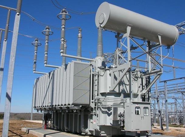
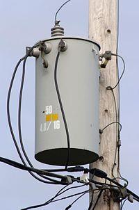
44 3-phase transformers The majority of the power generation/distribution systems in the world are 3- phase systems. The transformers for such circuits can be constructed either as a 3-phase bank of independent identical transformers (can be replaced independently) or as a single transformer wound on a single 3-legged core (lighter, cheaper, more efficient).

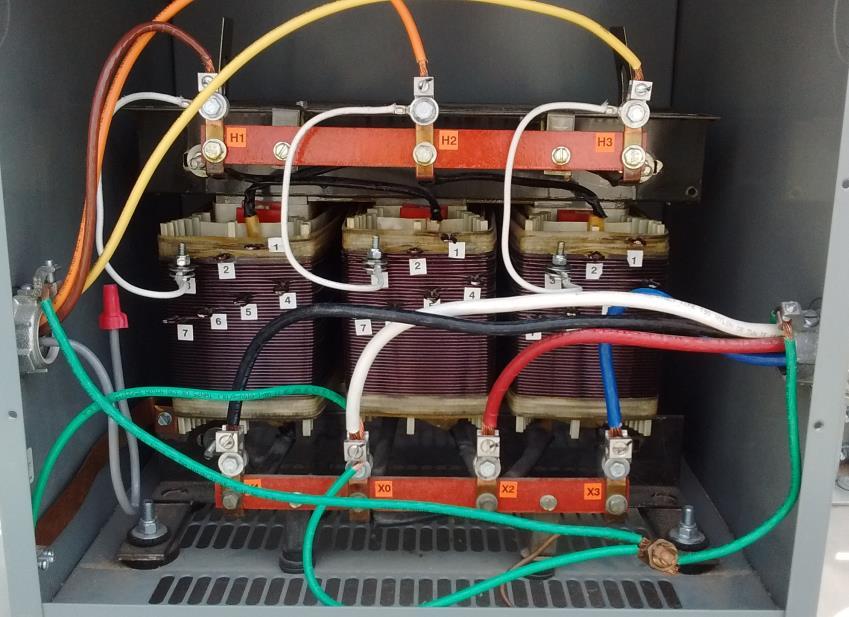
45 Core of 3-phase transformer
46 3-phase transformer connections We assume that any single transformer in a 3-phase transformer (bank) behaves exactly as a single-phase transformer. The impedance, voltage regulation, efficiency, and other calculations for 3-phase transformers are done on a per-phase basis, using the techniques studied previously for single-phase transformers. Four possible connections for a 3-phase transformer bank are: 1. Y-Y 2. Y Y
47 3-phase transformer connections 1. Y-Y connection: The primary voltage on each phase of the transformer is P LP The secondary phase voltage is LS 3 3 S The overall voltage ratio is LP LS 3 3 P S a
48 3-phase transformer connections 3. -Y connection: The primary voltage on each phase of the transformer is P LP The secondary phase voltage is LS 3 S The overall voltage ratio is LP LS P a 3 3 S The same advantages and the same phase shift as the Y- connection.
49 3-phase transformer connections 4. - connection: The primary voltage on each phase of the transformer is P LP The secondary phase voltage is LS S The overall voltage ratio is LP LS P S No phase shift, no problems with unbalanced loads or harmonics. a
50 3-phase transformer: per-unit system The per-unit system applies to the 3-phase transformers as well as to single-phase transformers. If the total base A value of the transformer bank is S base, the base A value of one of the transformers will be S1, base Therefore, the base phase current and impedance of the transformer are S1, base Sbase I, base 3 Z base, base S base 3, base 2, base 3, base S 1, base S base 2
51 3-phase transformer: per-unit system The line quantities on 3-phase transformer banks can also be represented in per-unit system. If the windings are in : If the windings are in Y: L, base, base L, base 3, base And the base line current in a 3-phase transformer bank is I L, base S 3 base L, base The application of the per-unit system to 3-phase transformer problems is similar to its application in single-phase situations. The voltage regulation of the transformer bank is the same.
52 Transformer ratings: oltage and Frequency The voltage rating is a) used to protect the winding insulation from breakdown; b) related to the magnetization current of the transformer (more important) If a steady-state voltage v( t) sint M is applied to the transformer s primary winding, the transformer s flux will be 1 M ( t) v( t) dt cost N N p An increase in voltage will lead to a proportional increase in flux. However, after some point (in a saturation region). This lead to an unacceptable increase in magnetization current! p flux Magnetization current
53 Transformer ratings: oltage and Frequency Therefore, the maximum applied voltage (and thus the rated voltage) is set by the maximum acceptable magnetization current in the core. We notice that the maximum flux is also related to the frequency: max max N p Therefore, to maintain the same maximum flux, a change in frequency (say, 50 Hz instead of 60 Hz) must be accompanied by the corresponding correction in the maximum allowed voltage. This reduction in applied voltage with frequency is called derating. As a result, a 50 Hz transformer may be operated at a 20% higher voltage on 60 Hz if this would not cause insulation damage.
54 Transformer ratings: Apparent Power The apparent power rating sets (together with the voltage rating) the current through the windings. The current determines the i 2 R losses and, therefore, the heating of the coils. Remember, overheating shortens the life of transformer s insulation! In addition to apparent power rating for the transformer itself, additional higher rating(s) may be specified if a forced cooling is used. Under any circumstances, the temperature of the windings must be limited. Note, that if the transformer s voltage is reduced (for instance, the transformer is working at a lower frequency), the apparent power rating must be reduced by an equal amount to maintain the constant current.
55 Transformer ratings: Current inrush Assuming that the following voltage is applied to the transformer at the moment it is connected to the line: v( t) sint M The maximum flux reached on the first half-cycle depends on the phase of the voltage at the instant the voltage is applied. If the initial voltage is v( t) sin t 90 cost M and the initial flux in the core is zero, the maximum flux during the first half-cycle is equals to the maximum steady-state flux (which is ok): max M N However, if the voltage s initial phase is zero, i.e. v( t) sint M p M
56 Transformer ratings: Current inrush the maximum flux during the first half-cycle will be max 1 N p 0 M 2 M M sin tdt cos t N N Which is twice higher than a normal steady-state flux! Doubling the maximum flux in the core can lead to saturation, thus may result in a huge magnetization current! Normally, the voltage phase angle cannot be controlled. As a result, a large inrush current is possible during the first several cycles after the transformer is turned ON. The transformer and the power system must be able to handle these currents. p 0 p

57 Typical Transformer Data Sheet

58 Instrument transformers Two special-purpose transformers are uses to take measurements: potential and current transformers. A potential transformer has a high-voltage primary, low-voltage secondary, and very low power rating. It is used to provide an accurate voltage samples to instruments monitoring the power system. A current transformer samples the current in a line and reduces it to a safe and measurable level. Such transformer consists of a secondary winding wrapped around a ferromagnetic ring with a single primary line running through its center. The secondary current is directly proportional to the primary. Current transformers must not be opencircuited since very high voltages can appear across their terminals.
59 Practice Problems
ECG 741 Power Distribution Transformers. Y. Baghzouz Spring 2014
 ECG 741 Power Distribution Transformers Y. Baghzouz Spring 2014 Preliminary Considerations A transformer is a device that converts one AC voltage to another AC voltage at the same frequency. The windings
IV. Three-Phase Transfomers
 I. Three-Phase Transfomers Three-Phase Transfomers The majority of the power generation/distribution systems in the world are 3- phase systems. The transformers for such circuits can be constructed either
Chapter 2-1 Transformers
 Principles of Electric Machines and Power Electronics Chapter 2-1 Transformers Third Edition P. C. Sen Transformer application 1: power transmission Ideal Transformer Assumptions: 1. Negligible winding
CHAPTER 2. Transformers. Dr Gamal Sowilam
 CHAPTER Transformers Dr Gamal Sowilam Introduction A transformer is a static machine. It is not an energy conversion device, it is indispensable in many energy conversion systems. A transformer essentially
El-Hawary, M.E. The Transformer Electrical Energy Systems. Series Ed. Leo Grigsby Boca Raton: CRC Press LLC, 2000
 El-Hawary, M.E. The Transformer Electrical Energy Systems. Series Ed. Leo Grigsby Boca Raton: CRC Press LLC, 000 97 Chapter 4 THE TRANSFORMER 4. NTRODUCTON The transformer is a valuable apparatus in electrical
Transformers 21.1 INTRODUCTION 21.2 MUTUAL INDUCTANCE
 21 Transformers 21.1 INTRODUCTION Chapter 12 discussed the self-inductance of a coil. We shall now examine the mutual inductance that exists between coils of the same or different dimensions. Mutual inductance
Chapter 2: Transformers
 Chapter 2: Transformers 2-1. The secondary winding of a transformer has a terminal voltage of v s (t) = 282.8 sin 377t V. The turns ratio of the transformer is 100:200 (a = 0.50). If the secondary current
Transformer: Load Factor
 Transformer Introduction Construction Theory of Operation Ideal Transformer Transformer Rating Equivalent Circuit Per-Unit System oltage Regulation Efficiency Tests No-Load Current and In-rush Current
APPLICATION NOTE - 018
 APPLICATION NOTE - 018 Power Transformers Background Power Transformers are used within an AC power distribution systems to increase or decrease the operating voltage to achieve the optimum transmission
Transmission Line Models Part 1
 Transmission Line Models Part 1 Unlike the electric machines studied so far, transmission lines are characterized by their distributed parameters: distributed resistance, inductance, and capacitance. The
The power transformer
 ELEC0014 - Introduction to power and energy systems The power transformer Thierry Van Cutsem t.vancutsem@ulg.ac.be www.montefiore.ulg.ac.be/~vct November 2017 1 / 35 Power transformers are used: to transmit
Transformers. Dr. Gamal Sowilam
 Transformers Dr. Gamal Sowilam OBJECTIVES Become familiar with the flux linkages that exist between the coils of a transformer and how the voltages across the primary and secondary are established. Understand
Spring 2000 EE361: MIDTERM EXAM 1
 NAME: STUDENT NUMBER: Spring 2000 EE361: MIDTERM EXAM 1 This exam is open book and closed notes. Assume f=60 hz and use the constant µ o =4π 10-7 wherever necessary. Be sure to show all work clearly. 1.
EE2022 Electrical Energy Systems
 EE0 Electrical Energy Systems Lecture : Transformer and Per Unit Analysis 7-0-0 Panida Jirutitijaroen Department of Electrical and Computer Engineering /9/0 EE0: Transformer and Per Unit Analysis by P.
% the leading currents. I(1,:) = amps.* ( j*0.6); % Lagging I(2,:) = amps.* ( 1.0 ); % Unity I(3,:) = amps.* ( j*0.
 = amps.* ( j*0.6); % Lagging I(2,:) = amps.* ( 1.0 ); % Unity I(3,:) = amps.* ( j*0.") % the leading currents. I(1,:) = amps.* ( 0.8 j*0.6); % Lagging I(,:) = amps.* ( 1.0 ); % Unity I(3,:) = amps.* ( 0.8 j*0.6); % Leading % Calculate VS referred to the primary side % for each current and
% the leading currents. I(1,:) = amps.* ( 0.8 j*0.6); % Lagging I(,:) = amps.* ( 1.0 ); % Unity I(3,:) = amps.* ( 0.8 j*0.6); % Leading % Calculate VS referred to the primary side % for each current and
Practical Transformer on Load
 Practical Transformer on Load We now consider the deviations from the last two ideality conditions : 1. The resistance of its windings is zero. 2. There is no leakage flux. The effects of these deviations
Module 7. Transformer. Version 2 EE IIT, Kharagpur
 Module 7 Transformer Lesson 28 Problem solving on Transformers Contents 28 Problem solving on Transformer (Lesson-28) 4 28.1 Introduction. 4 28.2 Problems on 2 winding single phase transformers. 4 28.3
SECTION 4 TRANSFORMERS. Yilu (Ellen) Liu. Associate Professor Electrical Engineering Department Virginia Tech University
 Liu. Associate Professor Electrical Engineering Department Virginia Tech University") SECTION 4 TRANSFORMERS Yilu (Ellen) Liu Associate Professor Electrical Engineering Department Virginia Tech University Analysis of Transformer Turns Ratio......................... 4.2 Analysis of a Step-Up
SECTION 4 TRANSFORMERS Yilu (Ellen) Liu Associate Professor Electrical Engineering Department Virginia Tech University Analysis of Transformer Turns Ratio......................... 4.2 Analysis of a Step-Up
UNIVERSITY OF TECHNOLOGY By: Fadhil A. Hasan ELECTRICAL MACHINES
 UNIVERSITY OF TECHNOLOGY DEPARTMENT OF ELECTRICAL ENGINEERING Year: Second 2016-2017 By: Fadhil A. Hasan ELECTRICAL MACHINES І Module-II: AC Transformers o Single phase transformers o Three-phase transformers
CHAPTER 4. Distribution Transformers
 CHAPTER 4 Distribution Transformers Introduction A transformer is an electrical device that transfers energy from one circuit to another purely by magnetic coupling. Relative motion of the parts of the
Transformers. gpmacademics.weebly.com
 TRANSFORMERS Syllabus: Principles of operation, Constructional Details, Losses and efficiency, Regulation of Transformer, Testing: OC & SC test. TRANSFORMER: It is a static device which transfers electric
86 chapter 2 Transformers
 86 chapter 2 Transformers Wb 1.2x10 3 0 1/60 2/60 3/60 4/60 5/60 6/60 t (sec) 1.2x10 3 FIGURE P2.2 2.3 A single-phase transformer has 800 turns on the primary winding and 400 turns on the secondary winding.
TRANSFORMER THEORY. Mutual Induction
 Transformers Transformers are used extensively for AC power transmissions and for various control and indication circuits. Knowledge of the basic theory of how these components operate is necessary to
CHAPTER 9. Sinusoidal Steady-State Analysis
 CHAPTER 9 Sinusoidal Steady-State Analysis 9.1 The Sinusoidal Source A sinusoidal voltage source (independent or dependent) produces a voltage that varies sinusoidally with time. A sinusoidal current source
Practical Tricks with Transformers. Larry Weinstein K0NA
 Practical Tricks with Transformers Larry Weinstein K0NA Practical Tricks with Transformers Quick review of inductance and magnetics Switching inductive loads How many voltages can we get out of a $10 Home
Chapter 33. Alternating Current Circuits
 Chapter 33 Alternating Current Circuits Alternating Current Circuits Electrical appliances in the house use alternating current (AC) circuits. If an AC source applies an alternating voltage to a series
148 Electric Machines
 148 Electric Machines 3.1 The emf per turn for a single-phase 2200/220- V, 50-Hz transformer is approximately 12 V. Calculate (a) the number of primary and secondary turns, and (b) the net cross-sectional
Department of Electrical and Computer Engineering Lab 6: Transformers
 ESE Electronics Laboratory A Department of Electrical and Computer Engineering 0 Lab 6: Transformers. Objectives ) Measure the frequency response of the transformer. ) Determine the input impedance of
Transformer & Induction M/C
 UNIT- 2 SINGLE-PHASE TRANSFORMERS 1. Draw equivalent circuit of a single phase transformer referring the primary side quantities to secondary and explain? (July/Aug - 2012) (Dec 2012) (June/July 2014)
CHAPTER 2. Basic Concepts, Three-Phase Review, and Per Unit
 CHAPTER 2 Basic Concepts, Three-Phase Review, and Per Unit 1 AC power versus DC power DC system: - Power delivered to the load does not fluctuate. - If the transmission line is long power is lost in the
SYNCHRONOUS MACHINES
 SYNCHRONOUS MACHINES The geometry of a synchronous machine is quite similar to that of the induction machine. The stator core and windings of a three-phase synchronous machine are practically identical
Electrical Machines I : Transformers
 UNIT TRANSFORMERS PART A (Q&A) 1. What is step down transformer? The transformer used to step down the voltage from primary to secondary is called as step down transformer. (Ex: /11).. Draw the noload
13. Magnetically Coupled Circuits
 13. Magnetically Coupled Circuits The change in the current flowing through an inductor induces (creates) a voltage in the conductor itself (self-inductance) and in any nearby conductors (mutual inductance)
Aligarh College of Engineering & Technology (College Code: 109) Affiliated to UPTU, Approved by AICTE Electrical Engg.
 Affiliated to UPTU, Approved by AICTE Electrical Engg.") Aligarh College of Engineering & Technology (College Code: 19) Electrical Engg. (EE-11/21) Unit-I DC Network Theory 1. Distinguish the following terms: (a) Active and passive elements (b) Linearity and
Aligarh College of Engineering & Technology (College Code: 19) Electrical Engg. (EE-11/21) Unit-I DC Network Theory 1. Distinguish the following terms: (a) Active and passive elements (b) Linearity and
INSTITUTE OF AERONAUTICAL ENGINEERING (Autonomous) Dundigal, Hyderabad
 Dundigal, Hyderabad") INSTITUTE OF AERONAUTICAL ENGINEERING (Autonomous) Dundigal, Hyderabad - 00 0 ELECTRICAL AND ELECTRONICS ENGINEERING QUESTION BANK Course Name Course Code Class Branch : ELECRICAL MACHINES - II : A0 :
INSTITUTE OF AERONAUTICAL ENGINEERING (Autonomous) Dundigal, Hyderabad - 00 0 ELECTRICAL AND ELECTRONICS ENGINEERING QUESTION BANK Course Name Course Code Class Branch : ELECRICAL MACHINES - II : A0 :
INSTITUTE OF AERONAUTICAL ENGINEERING (Autonomous) Dundigal, Hyderabad ELECTRICAL AND ELECTRONICS ENGINEERING
 Dundigal, Hyderabad ELECTRICAL AND ELECTRONICS ENGINEERING") Course Name Course Code Class Branch INSTITUTE OF AERONAUTICAL ENGINEERING (Autonomous) Dundigal, Hyderabad - 500 043 ELECTRICAL AND ELECTRONICS ENGINEERING QUESTION BANK : ELECRICAL MACHINES I : A40212
Course Name Course Code Class Branch INSTITUTE OF AERONAUTICAL ENGINEERING (Autonomous) Dundigal, Hyderabad - 500 043 ELECTRICAL AND ELECTRONICS ENGINEERING QUESTION BANK : ELECRICAL MACHINES I : A40212
cos sin XqIq cos sin V X Consider a simple case ignoring R a and X l d axis q axis V q I q V d I d Approximately, the second item can be ignored:
 Consider a simple case ignoring R a and X l E cos XdId I d E X d cos sin XqIq E E jxdid jxqi q jxdid q jx I d axis q axis I q q d q q I q sin X q d P3 3 I a cos I d I cos abdei cos I sin a q d E Xd Xq
PHYS 1442 Section 004 Lecture #15
 PHYS 1442 Section 004 Lecture #15 Monday March 17, 2014 Dr. Andrew Brandt Chapter 21 Generator Transformer Inductance 3/17/2014 1 PHYS 1442-004, Dr. Andrew Brandt Announcements HW8 on Ch 21-22 will be
EEE3441 Electrical Machines Department of Electrical Engineering. Lecture. Basic Operating Principles of Transformers
 Department of Electrical Engineering Lecture Basic Operating Principles of Transformers In this Lecture Basic operating principles of following transformers are introduced Single-phase Transformers Three-phase
TRANSFORMERS PART A. 2. What is the turns ratio and transformer ratio of transformer? Turns ratio = N2/ N1 Transformer = E2/E1 = I1/ I2 =K
 UNIT II TRANSFORMERS PART A 1. Define a transformer? A transformer is a static device which changes the alternating voltage from one level to another. 2. What is the turns ratio and transformer ratio of
ISSN: X Impact factor: (Volume 3, Issue 6) Available online at Modeling and Analysis of Transformer
 Available online at Modeling and Analysis of Transformer") ISSN: 2454-132X Impact factor: 4.295 (Volume 3, Issue 6) Available online at www.ijariit.com Modeling and Analysis of Transformer Divyapradeepa.T Department of Electrical and Electronics, Rajalakshmi Engineering
ISSN: 2454-132X Impact factor: 4.295 (Volume 3, Issue 6) Available online at www.ijariit.com Modeling and Analysis of Transformer Divyapradeepa.T Department of Electrical and Electronics, Rajalakshmi Engineering
Comparison of Leakage Impedances of Two Single-phase Transformers
 Aim Comparison of Leakage Impedances of Two Single-phase Transformers To understand the effect of core construction on leakage impedance in a single-phase transformers To understand factors affecting leakage
WELCOME TO THE LECTURE
 WLCOM TO TH LCTUR ON TRNFORMR Single Phase Transformer Three Phase Transformer Transformer transformer is a stationary electric machine which transfers electrical energy (power) from one voltage level
INSTITUTE OF AERONAUTICAL ENGINEERING (Autonomous) Dundigal, Hyderabad
 Dundigal, Hyderabad") INSTITUTE OF AERONAUTICAL ENGINEERING (Autonomous) Dundigal, Hyderabad - 00 03 ELECTRICAL AND ELECTRONICS ENGINEERING ASSIGNMENT Course Name : ELECRICAL MACHINES - II Course Code : A0 Class : II B.TECH-II
INSTITUTE OF AERONAUTICAL ENGINEERING (Autonomous) Dundigal, Hyderabad - 00 03 ELECTRICAL AND ELECTRONICS ENGINEERING ASSIGNMENT Course Name : ELECRICAL MACHINES - II Course Code : A0 Class : II B.TECH-II
ELECTRICAL ENGINEERING ESE TOPIC WISE OBJECTIVE SOLVED PAPER-II
 ELECTRICAL ENGINEERING ESE TOPIC WISE OBJECTIVE SOLVED PAPER-II From (1992 2017) Office : F-126, (Lower Basement), Katwaria Sarai, New Delhi-110016 Phone : 011-26522064 Mobile : 8130909220, 9711853908
Course ELEC Introduction to electric power and energy systems. Additional exercises with answers December reactive power compensation
 Course ELEC0014 - Introduction to electric power and energy systems Additional exercises with answers December 2017 Exercise A1 Consider the system represented in the figure below. The four transmission
Walchand Institute of Technology. Basic Electrical and Electronics Engineering. Transformer
 Walchand Institute of Technology Basic Electrical and Electronics Engineering Transformer 1. What is transformer? explain working principle of transformer. Electrical power transformer is a static device
EE 221 Circuits II. Chapter 13 Magnetically Coupled Circuits
 EE Circuits II Chapter 3 Magnetically Coupled Circuits Magnetically Coupled Circuits 3. What is a transformer? 3. Mutual Inductance 3.3 Energy in a Coupled Circuit 3.4 inear Transformers 3.5 Ideal Transformers
Transformer Waveforms
 OBJECTIVE EXPERIMENT Transformer Waveforms Steady-State Testing and Performance of Single-Phase Transformers Waveforms The voltage regulation and efficiency of a distribution system are affected by the
LC Resonant Circuits Dr. Roger King June Introduction
 LC Resonant Circuits Dr. Roger King June 01 Introduction Second-order systems are important in a wide range of applications including transformerless impedance-matching networks, frequency-selective networks,
MAHARASHTRA STATE BOARD OF TECHNICAL EDUCATION
 Important Instructions to examiners: 1) The answers should be examined by key words and not as word-to-word as given in the model answer scheme. 2) The model answer and the answer written by candidate
ECE 241L Fundamentals of Electrical Engineering. Experiment 8 A-C Transformer, Magnetization & Hysteresis
 ECE 241L Fundamentals of Electrical Engineering Experiment 8 A-C Transformer, Magnetization & Hysteresis A. Objectives: I. Measure leakage inductance and resistance loss II. Measure magnetization inductance
PHYS 1441 Section 001 Lecture #22 Wednesday, Nov. 29, 2017
 PHYS 1441 Section 001 Lecture #22 Chapter 29:EM Induction & Faraday s Law Transformer Electric Field Due to Changing Magnetic Flux Chapter 30: Inductance Mutual and Self Inductance Energy Stored in Magnetic
Review: Lecture 9. Instantaneous and Average Power. Effective or RMS Value. Apparent Power and Power Factor. Complex Power. Conservation of AC Power
 Review: Lecture 9 Instantaneous and Average Power p( t) VmI m cos ( v i ) VmI m cos ( t v i ) Maximum Average Power Transfer Z L R L jx Effective or RMS Value I rms I m L R P * TH Apparent Power and Power
Transformer. V1 is 1.0 Vp-p at 10 Khz. William R. Robinson Jr. p1of All rights Reserved
 V1 is 1.0 Vp-p at 10 Khz Step Down Direction Step Up Direction William R. Robinson Jr. p1of 24 Purpose To main purpose is to understand the limitations of the B2Spice simulator transformer model that I
ESO 210 Introduction to Electrical Engineering
 ESO 210 Introduction to Electrical Engineering Lecture-14 Three Phase AC Circuits 2 THE -CONNECTED GENERATOR If we rearrange the coils of the generator as shown in Fig. below the system is referred to
PROBLEMS on Transformers
 PROBLEMS on Transformers (A) Simple Problems 1. A single-phase, 250-kVA, 11-kV/415-V, 50-Hz transformer has 80 turns on the secondary. Calculate (a) the approximate values of the primary and secondary
ECE 3600 Transformers b
 Transformer basics and ratings A Transformer is two coils of wire that are magnetically coupled. Transformers b Transformers are only useful for AC, which is one of the big reasons electrical power is
PHYS 1444 Section 501 Lecture #20
 PHYS 1444 Section 501 Lecture #0 Monday, Apr. 17, 006 Transformer Generalized Faraday s Law Inductance Mutual Inductance Self Inductance Inductor Energy Stored in the Magnetic Field 1 Announcements Quiz
TRANSFORMERS INTRODUCTION
 Tyco Electronics Corporation Crompton Instruments 1610 Cobb International Parkway, Unit #4 Kennesaw, GA 30152 Tel. 770-425-8903 Fax. 770-423-7194 TRANSFORMERS INTRODUCTION A transformer is a device that
Module 1. Introduction. Version 2 EE IIT, Kharagpur
 Module 1 Introduction Lesson 1 Introducing the Course on Basic Electrical Contents 1 Introducing the course (Lesson-1) 4 Introduction... 4 Module-1 Introduction... 4 Module-2 D.C. circuits.. 4 Module-3
UNIT 1 CIRCUIT ANALYSIS 1 What is a graph of a network? When all the elements in a network is replaced by lines with circles or dots at both ends.
 UNIT 1 CIRCUIT ANALYSIS 1 What is a graph of a network? When all the elements in a network is replaced by lines with circles or dots at both ends. 2 What is tree of a network? It is an interconnected open
UNIT 4 TRANSFORMER 4.1 INTRODUCTION. Structure. 4.1 Introduction. 4.2 Basics of Transformer. 4.3 Equivalent Circuit of Transformer
 UT 4 TRASFORMR Transformer Structure 4. ntroduction Objectives 4. Basics of Transformer 4.. ntroduction 4.. MF quation of a Transformer 4..3 Construction 4.3 quivalent Circuit of Transformer 4.3. quivalent
Resonant Power Conversion
 Resonant Power Conversion Prof. Bob Erickson Colorado Power Electronics Center Department of Electrical, Computer, and Energy Engineering University of Colorado, Boulder Outline. Introduction to resonant
EQUIVALENT CIRCUIT OF A SINGLE-PHASE TRANSFORMER
 Electrical Machines Lab Experiment-No. One Date: 15-11-2016 EQUIVALENT CIRCUIT OF A SINGLE-PHASE TRANSFORMER Aim: The determination of electrical equivalent circuit parameters of a single phase power transformer
Chapter 33. Alternating Current Circuits
 Chapter 33 Alternating Current Circuits C HAP T E O UTLI N E 33 1 AC Sources 33 2 esistors in an AC Circuit 33 3 Inductors in an AC Circuit 33 4 Capacitors in an AC Circuit 33 5 The L Series Circuit 33
Downloaded From All JNTU World
 Code: 9A02403 GENERATION OF ELECTRIC POWER 1 Discuss the advantages and disadvantages of a nuclear plant as compared to other conventional power plants. 2 Explain about: (a) Solar distillation. (b) Solar
TESTS ON THE TRANSFORMER (E-13)
") SILESIA IVERSITY OF TECHOLOGY FACLTY OF EERGY AD EVIROMETAL EGIEERIG TESTS O THE TRASFORMER (E-3) Opracował: Dr inż. Mateusz Brzęczek Sprawdził: Dr inż. Włodzimierz Ogulewicz atwierdził: TESTS O THE TRASFORMER.
SILESIA IVERSITY OF TECHOLOGY FACLTY OF EERGY AD EVIROMETAL EGIEERIG TESTS O THE TRASFORMER (E-3) Opracował: Dr inż. Mateusz Brzęczek Sprawdził: Dr inż. Włodzimierz Ogulewicz atwierdził: TESTS O THE TRASFORMER.
Generalized Theory Of Electrical Machines
 Essentials of Rotating Electrical Machines Generalized Theory Of Electrical Machines All electrical machines are variations on a common set of fundamental principles, which apply alike to dc and ac types,
Operating principle of a transformer
 Transformers Operating principle of a transformer Transformers are stationary electrical machines which transmit energy from systems with certain current and voltage values into systems with generally
13 th Asian Physics Olympiad India Experimental Competition Wednesday, 2 nd May 2012
 13 th Asian Physics Olympiad India Experimental Competition Wednesday, nd May 01 Please first read the following instructions carefully: 1. The time available is ½ hours for each of the two experimental
Chapter 16: Mutual Inductance
 Chapter 16: Mutual Inductance Instructor: Jean-François MILLITHALER http://faculty.uml.edu/jeanfrancois_millithaler/funelec/spring2017 Slide 1 Mutual Inductance When two coils are placed close to each
Transformer Differential Protection Lab
 Montana Tech Library Digital Commons @ Montana Tech Proceedings of the Annual Montana Tech Electrical and General Engineering Symposium Student Scholarship 2016 Transformer Differential Protection Lab
Experiment No. Experiments for First Year Electrical Engg Lab
 Experiment No im: To determine Regulation and Efficiency of a single phase transformer using open circuit (O.C.) and short circuit (S.C.) tests pparatus: - Single phase transformer Single phase dimmer
DESIGN AND CONSTRUCTION OF 1500VA VARIABLE OUTPUT STEP DOWN TRANSFORMER
 DESIGN AND CONSTRUCTION OF 1500VA VARIABLE OUTPUT STEP DOWN TRANSFORMER OGUNDARE AYOADE B., OMOGOYE O. SAMUEL & OLUWASANYA OMOTAYO J. Department of Electrical/Electronic engineering, Lagos State Polytechnic,
Chapter 11. Alternating Current
 Unit-2 ECE131 BEEE Chapter 11 Alternating Current Objectives After completing this chapter, you will be able to: Describe how an AC voltage is produced with an AC generator (alternator) Define alternation,
Reg. No. : BASIC ELECTRICAL TECHNOLOGY (ELE 101)
") Department of Electrical and Electronics Engineering Reg. No. : MNIPL INSTITUTE OF TECHNOLOGY, MNIPL ( Constituent Institute of Manipal University, Manipal) FIRST SEMESTER B.E. DEGREE MKEUP EXMINTION (REVISED
Department of Electrical and Electronics Engineering Reg. No. : MNIPL INSTITUTE OF TECHNOLOGY, MNIPL ( Constituent Institute of Manipal University, Manipal) FIRST SEMESTER B.E. DEGREE MKEUP EXMINTION (REVISED
3. What is hysteresis loss? Also mention a method to minimize the loss. (N-11, N-12)
") DHANALAKSHMI COLLEGE OF ENGINEERING, CHENNAI DEPARTMENT OF ELECTRICAL AND ELECTRONICS ENGINEERING EE 6401 ELECTRICAL MACHINES I UNIT I : MAGNETIC CIRCUITS AND MAGNETIC MATERIALS Part A (2 Marks) 1. List
DHANALAKSHMI COLLEGE OF ENGINEERING, CHENNAI DEPARTMENT OF ELECTRICAL AND ELECTRONICS ENGINEERING EE 6401 ELECTRICAL MACHINES I UNIT I : MAGNETIC CIRCUITS AND MAGNETIC MATERIALS Part A (2 Marks) 1. List
Alternating current circuits- Series RLC circuits
 FISI30 Física Universitaria II Professor J.. ersosimo hapter 8 Alternating current circuits- Series circuits 8- Introduction A loop rotated in a magnetic field produces a sinusoidal voltage and current.
AC Power Instructor Notes
 Chapter 7: AC Power Instructor Notes Chapter 7 surveys important aspects of electric power. Coverage of Chapter 7 can take place immediately following Chapter 4, or as part of a later course on energy
By Gill ( ) PDF created with FinePrint pdffactory trial version
 PDF created with FinePrint pdffactory trial version") By Gill (www.angelfire.com/al4/gill ) 1 Introduction One of the main reasons of adopting a.c. system instead of d.c. for generation, transmission and distribution of electrical power is that alternatin
By Gill (www.angelfire.com/al4/gill ) 1 Introduction One of the main reasons of adopting a.c. system instead of d.c. for generation, transmission and distribution of electrical power is that alternatin
CHAPTER 2 D-Q AXES FLUX MEASUREMENT IN SYNCHRONOUS MACHINES
 22 CHAPTER 2 D-Q AXES FLUX MEASUREMENT IN SYNCHRONOUS MACHINES 2.1 INTRODUCTION For the accurate analysis of synchronous machines using the two axis frame models, the d-axis and q-axis magnetic characteristics
1 K Hinds 2012 TRANSFORMERS
 1 K Hinds 2012 TRANSFORMERS A transformer changes electrical energy of a given voltage into electrical energy at a different voltage level. It consists of two coils which are not electrically connected,
Chapter Three. Magnetic Integration for Multiphase VRMs
 Chapter Three Magnetic Integration for Multiphase VRMs Integrated magnetic components are used in multiphase VRMs in order to reduce the number of the magnetics and to improve efficiency. All the magnetic
University of Jordan School of Engineering Electrical Engineering Department. EE 219 Electrical Circuits Lab
 University of Jordan School of Engineering Electrical Engineering Department EE 219 Electrical Circuits Lab EXPERIMENT 7 RESONANCE Prepared by: Dr. Mohammed Hawa EXPERIMENT 7 RESONANCE OBJECTIVE This experiment
Transformers. ELG3311: Habash,
 Transformers A transformer is a device that changes AC electric power at one voltage level to AC electric power at another voltage level through the action of magnetic field. t consists of two or more
VALLIAMMAI ENGINEERING COLLEGE
 VALLIAMMAI ENGINEERING COLLEGE SRM Nagar, Kattankulathur 603 203 DEPARTMENT OF ELECTRONICS AND INSTRUMENTATION ENGINEERING QUESTION BANK IV SEMESTER EI6402 ELECTRICAL MACHINES Regulation 2013 Academic
Engineering Science OUTCOME 4 - TUTORIAL 3 CONTENTS. 1. Transformers
 Unit : Unit code: QCF Level: 4 Credit value: 5 SYLLABUS Engineering Science L/60/404 OUTCOME 4 - TUTOIAL 3 Be able to apply single phase AC theory to solve electrical and electronic engineering problems
AUTO-TRANSFORMER. This is having only one winding; part of this winding is common to both primary and secondary.
 AUTO-TRANSFORMER This is having only one winding; part of this winding is common to both primary and secondary. In 2-winding transformer both primary and secondary windings are electrically isolated, but
Core Technology Group Application Note 1 AN-1
 Measuring the Impedance of Inductors and Transformers. John F. Iannuzzi Introduction In many cases it is necessary to characterize the impedance of inductors and transformers. For instance, power supply
Generator Advanced Concepts
 Generator Advanced Concepts Common Topics, The Practical Side Machine Output Voltage Equation Pitch Harmonics Circulating Currents when Paralleling Reactances and Time Constants Three Generator Curves
AC Excitation. AC Excitation 1. Introduction
 AC Excitation 1 AC Excitation Introduction Transformers are foundational elements in all power distribution systems. A transformer couples two (or more) coils to the same flux. As long as the flux is changing
SHRI RAMSWAROOP MEMORIAL COLLEGE OF ENGG. & MANAGEMENT B.Tech. [SEM I (EE, EN, EC, CE)] QUIZ TEST-3 (Session: ) Time: 1 Hour ELECTRICAL ENGINEE
![SHRI RAMSWAROOP MEMORIAL COLLEGE OF ENGG. & MANAGEMENT B.Tech. [SEM I (EE, EN, EC, CE)] QUIZ TEST-3 (Session: ) Time: 1 Hour ELECTRICAL ENGINEE](/thumbs/94/118213481.jpg "SHRI RAMSWAROOP MEMORIAL COLLEGE OF ENGG. & MANAGEMENT B.Tech. [SEM I (EE, EN, EC, CE)] QUIZ TEST-3 (Session: ) Time: 1 Hour ELECTRICAL ENGINEE") SHRI RAMSWAROOP MEMORIAL COLLEGE OF ENGG. & MANAGEMENT B.Tech. [SEM I (EE, EN, EC, CE)] QUIZ TEST-3 (Session: 2014-15) Time: 1 Hour ELECTRICAL ENGINEERING Max. Marks: 30 (NEE-101) Roll No. Academic/26
SHRI RAMSWAROOP MEMORIAL COLLEGE OF ENGG. & MANAGEMENT B.Tech. [SEM I (EE, EN, EC, CE)] QUIZ TEST-3 (Session: 2014-15) Time: 1 Hour ELECTRICAL ENGINEERING Max. Marks: 30 (NEE-101) Roll No. Academic/26
Electrical Circuits and Systems
 Electrical Circuits and Systems Macmillan Education Basis Books in Electronics Series editor Noel M. Morris Digital Electronic Circuits and Systems Linear Electronic Circuits and Systems Electronic Devices
Module 7. Transformer. Version 2 EE IIT, Kharagpur
 Module 7 Transformer Lesson 3 Ideal Transformer Contents 3 Ideal Transformer (Lesson: 3) 4 3. Goals of the lesson 4 3. Introduction.. 5 3.. Principle of operation.. 5 3.3 Ideal Transformer.. 6 3.3. Core
 VIDYARTHIPLUS - ANNA UNIVERSITY ONLINE STUDENTS COMMUNITY UNIT 1 DC MACHINES PART A 1. State Faraday s law of Electro magnetic induction and Lenz law. 2. Mention the following functions in DC Machine (i)
Bakiss Hiyana binti Abu Bakar JKE, POLISAS BHAB
 1 Bakiss Hiyana binti Abu Bakar JKE, POLISAS 1. Explain AC circuit concept and their analysis using AC circuit law. 2. Apply the knowledge of AC circuit in solving problem related to AC electrical circuit.
CHIEF ENGINEER REG III/2 MARINE ELECTROTECHNOLOGY
 CHIEF ENGINEER REG III/2 MARINE ELECTROTECHNOLOGY LIST OF TOPICS 1 Electric Circuit Principles 2 Electronic Circuit Principles 3 Generation 4 Distribution 5 Utilisation The expected learning outcome is
TECHNICAL BULLETIN 004a Ferroresonance
 May 29, 2002 TECHNICAL BULLETIN 004a Ferroresonance Abstract - This paper describes the phenomenon of ferroresonance, the conditions under which it may appear in electric power systems, and some techniques
EE 740 Transmission Lines
 EE 740 Transmission Lines 1 High Voltage Power Lines (overhead) Common voltages in north America: 138, 230, 345, 500, 765 kv Bundled conductors are used in extra-high voltage lines Stranded instead of