ECG 741 Power Distribution Transformers. Y. Baghzouz Spring 2014
|
|
|
- Suzanna Griffith
- 6 years ago
- Views:
Transcription

1 ECG 741 Power Distribution Transformers Y. Baghzouz Spring 2014


2 Preliminary Considerations A transformer is a device that converts one AC voltage to another AC voltage at the same frequency. The windings are wrapped on top of each other to decrease flux leakage.
3 Ideal Transformer An ideal transformer (unlike the real one) can be characterized as follows: 1.The core has no hysteresis nor eddy currents. 2.The magnetization curve is vertical with no saturation 3.The leakage flux in the core is zero. 4.The resistance of the windings is zero. Consider a lossless transformer with an input (primary) winding having N p turns and an output (secondary) winding of N s turns. The relationships between the voltage and current applied to the primary winding and the voltage and current produced on the secondary winding are V V p s a where a = N p /N s is the turn ratio of the transformer. I I p s 1 a


4 Lead Markings and Polarity Dot markings are used on instrument transformers. On power transformers, the terminals are designated by the symbols H1 and H2 for the high-voltage (HV) winding, and by X1 and X2 for the low-voltage (LV) winding. By convention, H1 and X1 have the same polarity (which can be additive or subtractive).

5 Power in an Ideal Transformer The output power of an ideal transformer equals to its input power to be expected since assumed no loss. Similarly, for reactive and apparent powers: P out Vp V I cos ai cos VI cos P a s s p p p in Q V I sin V I sin Q out s s p p in Sout Vs Is VpI p Sin Apparent impedance of the primary circuit: Z L ' V av V a I I a I p s 2 s 2 p s s a Z L
: p m Lp mutual flux leakage primary flux Similarly, for the secondary coil: s m Ls Leakage secondary flux")
6 Leakage Flux in Real Transformer A portion of the flux produced in the primary coil passes through the secondary coil (mutual flux); the rest passes through the external medium (leakage flux): p m Lp mutual flux leakage primary flux Similarly, for the secondary coil: s m Ls Leakage secondary flux
7 Excitation Current in a Real Transformer Even when no load is connected to the secondary coil of the transformer, a current will flow in the primary coil. This current consists of: 1. Magnetization current i m is needed to produce the flux in the core; 2. Core-loss current i h+e corresponds to hysteresis and eddy current losses. Flux causing the magnetization current Typical magnetization curve
8 Saturation curves of magnetic and nonmagnetic materials


9 Excitation Current in a Real Transformer total excitation current in a transformer Core-loss current Core-loss current is: 1. Nonlinear due to nonlinear effects of hysteresis; 2. In phase with the voltage. The total no-load current in the core is called the excitation current of the transformer: i i i ex m h e

10 Equivalent Circuit of a Real Transformer Cooper losses are modeled by the resistors R p and R s. The leakage flux can be modeled by primary and secondary inductors. The magnetization current can be modeled by a reactance X M connected across the primary voltage source. The core-loss current can be modeled by a resistance R C connected across the primary voltage source. Both magnetizing and core loss currents are nonlinear; therefore, X M and R C are just approximations.

11 Equivalent Circuit of a Real Transformer The equivalent circuit is usually referred to the primary side or the secondary side of the transformer. Equivalent circuit of the transformer referred to its primary side. Equivalent circuit of the transformer referred to its secondary side.

12 Approximate Equivalent Circuit of a Real Transformer Referred to the primary side Referred to the secondary side. Without an excitation branch referred to the primary side. Without an excitation branch referred to the secondary side.
13 Example Example 4.2: Determine the equivalent circuit impedances of a 20 kva, 8000/240 V, 60 Hz transformer. The open-circuit and short-circuit tests led to the following data: V OC = 8000 V I OC = A P OC = 400 W V SC = 489 V I SC = 2.5 A P SC = 240 W 1 1 RC 159 k; X M 38.3 k R eq 38.3 ; X 192 eq
14 The per-unit system The voltages, currents, powers, impedances, and other electrical quantities are measured as fractions of some base level instead of conventional units. actualvalue Quantity perunit basevalue of quantity Usually, two base quantities are selected to define a given per-unit system. Often, such quantities are voltage and apparent power. In a single-phase circuits: P, Q, ors V I Z base base base base base base V I base base V 2 S base base Y base I V base base
15 base1 base1 base1 base1 The per-unit system: Example Example 4.4: Sketch the appropriate per-unit equivalent circuit for the 8000/240 V, 60 Hz, 20 kva transformer with R c = 159 k, X M = 38.4 k, R eq = 38.3, X eq = 192. To convert the transformer to per-unit system, the primary circuit base impedance needs to be found. V 8000 V ; S 20000VA Z 2 2 Vbase S j192 ZSE, pu j0.06 pu RC, pu 49.7 pu X M, pu 12 pu 3200
16 Voltage Regulation (VR) Since a real transformer contains series impedances, the transformer s output voltage varies with the load even if the input voltage is constant. To compare transformers in this respect, the quantity called a full-load voltage regulation (VR) is defined as follows: VR V V V a V 100% 100% V V s, nl s, fl p s, fl s, fl s, fl In a per-unit system: VR V V p, pu s, fl, pu V s, fl, pu 100% Where V s,nl and V s,fl are the secondary no load and full load voltages.
17 Transformer Phasor Diagram Usually, the effects of the excitation branch on transformer VR can be ignored and, therefore, only the series impedances need to be considered. The VR depends on the magnitude of the impedances and on the current phase angle. V V R I jx I p s eq s eq s a
18 Transformer Efficiency Pout Pout 100% 100% P P P in out loss VI s scos 100% P P V I cos Cu core s s 1. Copper (I 2 R) losses are accounted for by the series resistance R s 2. Hysteresis and eddy current losses are accounted for by R c.
19 Transformer efficiency: Example Example 4.5: A 15 kva, 2300/230 V transformer was tested to by open-circuit and closed-circuit tests. The following data was obtained: V OC = 2300 V I OC = 0.21 A P OC = 50 W V SC = 47 V I SC = 6.0 A P SC = 160 W a) Find the equivalent circuit of this transformer referred to the high-voltage side. b) Find the equivalent circuit of this transformer referred to the low-voltage side. c) Calculate the full-load voltage regulation at 0.8 lagging power factor, at 1.0 power factor, and at 0.8 leading power factor. d) Plot the voltage regulation as load is increased from no load to full load at power factors of 0.8 lagging, 1.0, and 0.8 leading. e) What is the efficiency of the transformer at full load with a power factor of 0.8 lagging?
20 Transformer efficiency: Example Pout 100% 98.03% P P P Cu core out
21 Loading Ratio: Transformer Paralleling
22 Transformer Paralleling - Example 100 kva transformer is connected in parallel with a 250 kva. The two transformers are rated at 7,200V/240V, but the 100 kva unit has an impedance of 4% and the 250 kva unit has an impedance of 6%. Calculate the following: Nominal primary current of each transformer (ans: 34.7 A and 13.9 A) The impedance of each transformer referred to the primary side (ans: 12.4 and 20.7 Ohms). Loading ratio (ans. 0.6) If the loading on the100 kva transformer is 100 kva, then the loading on the 250 kva transformer is (ans kva) If the loading on the 250 kva transformer is 250 kva, then the loading on the 100 kva transformer is (ans. 150 kva) Calculate the rating of the parallel transformer combination (Ans kva) Assume the transformers supply a load of 330 kva. Calculate the following: The impedance of the load referred to the primary side (ans: 157 Ohms) The actual primary current in each transformer (ans: 28.8 A and 17.2A) The loading on each transformer (ans kva and kva)
23 1-Phase Transformer with 3-wire Secondary
24 Example
25 Transformer ratings: Voltage and Frequency The voltage rating is a) used to protect the winding insulation from breakdown; b) related to the magnetization current of the transformer (more important) If a steady-state voltage v( t) V sint M is applied to the transformer s primary winding, the transformer s flux will be 1 VM ( t) v( t) dt cost N N p An increase in voltage will lead to a proportional increase in flux. However, after some point (in a saturation region), such increase in flux would require an unacceptable increase in magnetization current! p flux Magnetization current
26 Transformer ratings: Voltage and Frequency Therefore, the maximum applied voltage (and thus the rated voltage) is set by the maximum acceptable magnetization current in the core. We notice that the maximum flux is also related to the frequency: max V max N p Therefore, to maintain the same maximum flux, a change in frequency (say, 50 Hz instead of 60 Hz) must be accompanied by the corresponding correction in the maximum allowed voltage. This reduction in applied voltage with frequency is called derating. As a result, a 50 Hz transformer may be operated at a 20% higher voltage on 60 Hz if this would not cause insulation damage.
27 Transformer ratings: Apparent Power The apparent power rating sets (together with the voltage rating) the current through the windings. The current determines the i 2 R losses and, therefore, the heating of the coils. Remember, overheating shortens the life of transformer s insulation! In addition to apparent power rating for the transformer itself, additional higher rating(s) may be specified if a forced cooling is used. Under any circumstances, the temperature of the windings must be limited. Note, that if the transformer s voltage is reduced (for instance, the transformer is working at a lower frequency), the apparent power rating must be reduced by an equal amount to maintain the constant current.
28 Transformer ratings: Current inrush Assuming that the following voltage is applied to the transformer at the moment it is connected to the line: v( t) V sint M The maximum flux reached on the first half-cycle depends on the phase of the voltage at the instant the voltage is applied. If the initial voltage is v( t) V sin t 90 V cost M and the initial flux in the core is zero, the maximum flux during the first half-cycle is equals to the maximum steady-state flux (which is ok): max VM N However, if the voltage s initial phase is zero, i.e. v( t) V sint M p M
29 Transformer ratings: Current inrush the maximum flux during the first half-cycle will be max 1 N p 0 VM 2V M VM sin tdt cos t N N p 0 p Which is twice higher than a normal steady-state flux! Doubling the maximum flux in the core can bring the core in a saturation and, therefore, may result in a huge magnetization current! Normally, the voltage phase angle cannot be controlled. As a result, a large inrush current is possible during the first several cycles after the transformer is turned ON. The transformer and the power system must be able to handle these currents.
EE 340 Power Transformers
 EE 340 Power Transformers Preliminary considerations A transformer is a device that converts one AC voltage to another AC voltage at the same frequency. It consists of one or more coil(s) of wire wrapped
Chapter 2-1 Transformers
 Principles of Electric Machines and Power Electronics Chapter 2-1 Transformers Third Edition P. C. Sen Transformer application 1: power transmission Ideal Transformer Assumptions: 1. Negligible winding
Module 7. Transformer. Version 2 EE IIT, Kharagpur
 Module 7 Transformer Lesson 28 Problem solving on Transformers Contents 28 Problem solving on Transformer (Lesson-28) 4 28.1 Introduction. 4 28.2 Problems on 2 winding single phase transformers. 4 28.3
Chapter 2: Transformers
 Chapter 2: Transformers 2-1. The secondary winding of a transformer has a terminal voltage of v s (t) = 282.8 sin 377t V. The turns ratio of the transformer is 100:200 (a = 0.50). If the secondary current
Transmission Line Models Part 1
 Transmission Line Models Part 1 Unlike the electric machines studied so far, transmission lines are characterized by their distributed parameters: distributed resistance, inductance, and capacitance. The
Transformer: Load Factor
 Transformer Introduction Construction Theory of Operation Ideal Transformer Transformer Rating Equivalent Circuit Per-Unit System oltage Regulation Efficiency Tests No-Load Current and In-rush Current
PROBLEMS on Transformers
 PROBLEMS on Transformers (A) Simple Problems 1. A single-phase, 250-kVA, 11-kV/415-V, 50-Hz transformer has 80 turns on the secondary. Calculate (a) the approximate values of the primary and secondary
148 Electric Machines
 148 Electric Machines 3.1 The emf per turn for a single-phase 2200/220- V, 50-Hz transformer is approximately 12 V. Calculate (a) the number of primary and secondary turns, and (b) the net cross-sectional
86 chapter 2 Transformers
 86 chapter 2 Transformers Wb 1.2x10 3 0 1/60 2/60 3/60 4/60 5/60 6/60 t (sec) 1.2x10 3 FIGURE P2.2 2.3 A single-phase transformer has 800 turns on the primary winding and 400 turns on the secondary winding.
% the leading currents. I(1,:) = amps.* ( j*0.6); % Lagging I(2,:) = amps.* ( 1.0 ); % Unity I(3,:) = amps.* ( j*0.
 = amps.* ( j*0.6); % Lagging I(2,:) = amps.* ( 1.0 ); % Unity I(3,:) = amps.* ( j*0.") % the leading currents. I(1,:) = amps.* ( 0.8 j*0.6); % Lagging I(,:) = amps.* ( 1.0 ); % Unity I(3,:) = amps.* ( 0.8 j*0.6); % Leading % Calculate VS referred to the primary side % for each current and
% the leading currents. I(1,:) = amps.* ( 0.8 j*0.6); % Lagging I(,:) = amps.* ( 1.0 ); % Unity I(3,:) = amps.* ( 0.8 j*0.6); % Leading % Calculate VS referred to the primary side % for each current and
EE 221 Circuits II. Chapter 13 Magnetically Coupled Circuits
 EE Circuits II Chapter 3 Magnetically Coupled Circuits Magnetically Coupled Circuits 3. What is a transformer? 3. Mutual Inductance 3.3 Energy in a Coupled Circuit 3.4 inear Transformers 3.5 Ideal Transformers
EQUIVALENT CIRCUIT OF A SINGLE-PHASE TRANSFORMER
 Electrical Machines Lab Experiment-No. One Date: 15-11-2016 EQUIVALENT CIRCUIT OF A SINGLE-PHASE TRANSFORMER Aim: The determination of electrical equivalent circuit parameters of a single phase power transformer
Practical Transformer on Load
 Practical Transformer on Load We now consider the deviations from the last two ideality conditions : 1. The resistance of its windings is zero. 2. There is no leakage flux. The effects of these deviations
CHAPTER 2. Transformers. Dr Gamal Sowilam
 CHAPTER Transformers Dr Gamal Sowilam Introduction A transformer is a static machine. It is not an energy conversion device, it is indispensable in many energy conversion systems. A transformer essentially
Transformer & Induction M/C
 UNIT- 2 SINGLE-PHASE TRANSFORMERS 1. Draw equivalent circuit of a single phase transformer referring the primary side quantities to secondary and explain? (July/Aug - 2012) (Dec 2012) (June/July 2014)
SECTION 4 TRANSFORMERS. Yilu (Ellen) Liu. Associate Professor Electrical Engineering Department Virginia Tech University
 Liu. Associate Professor Electrical Engineering Department Virginia Tech University") SECTION 4 TRANSFORMERS Yilu (Ellen) Liu Associate Professor Electrical Engineering Department Virginia Tech University Analysis of Transformer Turns Ratio......................... 4.2 Analysis of a Step-Up
SECTION 4 TRANSFORMERS Yilu (Ellen) Liu Associate Professor Electrical Engineering Department Virginia Tech University Analysis of Transformer Turns Ratio......................... 4.2 Analysis of a Step-Up
Transformers. gpmacademics.weebly.com
 TRANSFORMERS Syllabus: Principles of operation, Constructional Details, Losses and efficiency, Regulation of Transformer, Testing: OC & SC test. TRANSFORMER: It is a static device which transfers electric
Practical Tricks with Transformers. Larry Weinstein K0NA
 Practical Tricks with Transformers Larry Weinstein K0NA Practical Tricks with Transformers Quick review of inductance and magnetics Switching inductive loads How many voltages can we get out of a $10 Home
The power transformer
 ELEC0014 - Introduction to power and energy systems The power transformer Thierry Van Cutsem t.vancutsem@ulg.ac.be www.montefiore.ulg.ac.be/~vct November 2017 1 / 35 Power transformers are used: to transmit
EN Assignment No.1 - TRANSFORMERS
 EN-06 - Assignment No.1 - TRANSFORMERS Date : 13 th Jan 01 Q1) A 0kVA 00/0 Volts, 60Hz, single phase transformer is found to have the following equivalent circuit parameter referred to the high potential
SYNCHRONOUS MACHINES
 SYNCHRONOUS MACHINES The geometry of a synchronous machine is quite similar to that of the induction machine. The stator core and windings of a three-phase synchronous machine are practically identical
Transformers 21.1 INTRODUCTION 21.2 MUTUAL INDUCTANCE
 21 Transformers 21.1 INTRODUCTION Chapter 12 discussed the self-inductance of a coil. We shall now examine the mutual inductance that exists between coils of the same or different dimensions. Mutual inductance
Aligarh College of Engineering & Technology (College Code: 109) Affiliated to UPTU, Approved by AICTE Electrical Engg.
 Affiliated to UPTU, Approved by AICTE Electrical Engg.") Aligarh College of Engineering & Technology (College Code: 19) Electrical Engg. (EE-11/21) Unit-I DC Network Theory 1. Distinguish the following terms: (a) Active and passive elements (b) Linearity and
Aligarh College of Engineering & Technology (College Code: 19) Electrical Engg. (EE-11/21) Unit-I DC Network Theory 1. Distinguish the following terms: (a) Active and passive elements (b) Linearity and
APPLICATION NOTE - 018
 APPLICATION NOTE - 018 Power Transformers Background Power Transformers are used within an AC power distribution systems to increase or decrease the operating voltage to achieve the optimum transmission
EE2022 Electrical Energy Systems
 EE0 Electrical Energy Systems Lecture : Transformer and Per Unit Analysis 7-0-0 Panida Jirutitijaroen Department of Electrical and Computer Engineering /9/0 EE0: Transformer and Per Unit Analysis by P.
Course ELEC Introduction to electric power and energy systems. Additional exercises with answers December reactive power compensation
 Course ELEC0014 - Introduction to electric power and energy systems Additional exercises with answers December 2017 Exercise A1 Consider the system represented in the figure below. The four transmission
UNIVERSITY OF TECHNOLOGY By: Fadhil A. Hasan ELECTRICAL MACHINES
 UNIVERSITY OF TECHNOLOGY DEPARTMENT OF ELECTRICAL ENGINEERING Year: Second 2016-2017 By: Fadhil A. Hasan ELECTRICAL MACHINES І Module-II: AC Transformers o Single phase transformers o Three-phase transformers
Spring 2000 EE361: MIDTERM EXAM 1
 NAME: STUDENT NUMBER: Spring 2000 EE361: MIDTERM EXAM 1 This exam is open book and closed notes. Assume f=60 hz and use the constant µ o =4π 10-7 wherever necessary. Be sure to show all work clearly. 1.
EEE3441 Electrical Machines Department of Electrical Engineering. Lecture. Basic Operating Principles of Transformers
 Department of Electrical Engineering Lecture Basic Operating Principles of Transformers In this Lecture Basic operating principles of following transformers are introduced Single-phase Transformers Three-phase
Table of Contents. Table of Figures. Table of Tables
 Abstract The aim of this report is to investigate and test a transformer and check if it is good to use by doing the following tests continuity test, insulation test, polarity test, open circuit test,
Review: Lecture 9. Instantaneous and Average Power. Effective or RMS Value. Apparent Power and Power Factor. Complex Power. Conservation of AC Power
 Review: Lecture 9 Instantaneous and Average Power p( t) VmI m cos ( v i ) VmI m cos ( t v i ) Maximum Average Power Transfer Z L R L jx Effective or RMS Value I rms I m L R P * TH Apparent Power and Power
MAHARASHTRA STATE BOARD OF TECHNICAL EDUCATION
 Important Instructions to examiners: 1) The answers should be examined by key words and not as word-to-word as given in the model answer scheme. 2) The model answer and the answer written by candidate
Comparison of Leakage Impedances of Two Single-phase Transformers
 Aim Comparison of Leakage Impedances of Two Single-phase Transformers To understand the effect of core construction on leakage impedance in a single-phase transformers To understand factors affecting leakage
ECE 241L Fundamentals of Electrical Engineering. Experiment 8 A-C Transformer, Magnetization & Hysteresis
 ECE 241L Fundamentals of Electrical Engineering Experiment 8 A-C Transformer, Magnetization & Hysteresis A. Objectives: I. Measure leakage inductance and resistance loss II. Measure magnetization inductance
Open Circuit (OC) and Short Circuit (SC) Tests on Single Phase Transformer
 and Short Circuit (SC) Tests on Single Phase Transformer") Open Circuit (OC) and Short Circuit (SC) Tests on Single Phase Transformer 1 Aim To obtain the equivalent circuit parameters from OC and SC tests, and to estimate efficiency & regulation at various loads.
Open Circuit (OC) and Short Circuit (SC) Tests on Single Phase Transformer 1 Aim To obtain the equivalent circuit parameters from OC and SC tests, and to estimate efficiency & regulation at various loads.
CHAPTER 9. Sinusoidal Steady-State Analysis
 CHAPTER 9 Sinusoidal Steady-State Analysis 9.1 The Sinusoidal Source A sinusoidal voltage source (independent or dependent) produces a voltage that varies sinusoidally with time. A sinusoidal current source
EE2003 Circuit Theory Chapter 13 Magnetically Coupled Circuits
 EE003 Circuit Theory Chapter 3 Magnetically Coupled Circuits Copyright The McGraw-Hill Companies, Inc. Permission required for reproduction or display. Magnetically Coupled Circuit Chapter 3 3. What is
INSTITUTE OF AERONAUTICAL ENGINEERING (Autonomous) Dundigal, Hyderabad
 Dundigal, Hyderabad") INSTITUTE OF AERONAUTICAL ENGINEERING (Autonomous) Dundigal, Hyderabad - 00 0 ELECTRICAL AND ELECTRONICS ENGINEERING QUESTION BANK Course Name Course Code Class Branch : ELECRICAL MACHINES - II : A0 :
INSTITUTE OF AERONAUTICAL ENGINEERING (Autonomous) Dundigal, Hyderabad - 00 0 ELECTRICAL AND ELECTRONICS ENGINEERING QUESTION BANK Course Name Course Code Class Branch : ELECRICAL MACHINES - II : A0 :
INSTITUTE OF AERONAUTICAL ENGINEERING (Autonomous) Dundigal, Hyderabad
 Dundigal, Hyderabad") INSTITUTE OF AERONAUTICAL ENGINEERING (Autonomous) Dundigal, Hyderabad - 00 03 ELECTRICAL AND ELECTRONICS ENGINEERING ASSIGNMENT Course Name : ELECRICAL MACHINES - II Course Code : A0 Class : II B.TECH-II
INSTITUTE OF AERONAUTICAL ENGINEERING (Autonomous) Dundigal, Hyderabad - 00 03 ELECTRICAL AND ELECTRONICS ENGINEERING ASSIGNMENT Course Name : ELECRICAL MACHINES - II Course Code : A0 Class : II B.TECH-II
INSTITUTE OF AERONAUTICAL ENGINEERING (Autonomous) Dundigal, Hyderabad ELECTRICAL AND ELECTRONICS ENGINEERING
 Dundigal, Hyderabad ELECTRICAL AND ELECTRONICS ENGINEERING") Course Name Course Code Class Branch INSTITUTE OF AERONAUTICAL ENGINEERING (Autonomous) Dundigal, Hyderabad - 500 043 ELECTRICAL AND ELECTRONICS ENGINEERING QUESTION BANK : ELECRICAL MACHINES I : A40212
Course Name Course Code Class Branch INSTITUTE OF AERONAUTICAL ENGINEERING (Autonomous) Dundigal, Hyderabad - 500 043 ELECTRICAL AND ELECTRONICS ENGINEERING QUESTION BANK : ELECRICAL MACHINES I : A40212
Core Technology Group Application Note 1 AN-1
 Measuring the Impedance of Inductors and Transformers. John F. Iannuzzi Introduction In many cases it is necessary to characterize the impedance of inductors and transformers. For instance, power supply
ELECTRICAL ENGINEERING ESE TOPIC WISE OBJECTIVE SOLVED PAPER-II
 ELECTRICAL ENGINEERING ESE TOPIC WISE OBJECTIVE SOLVED PAPER-II From (1992 2017) Office : F-126, (Lower Basement), Katwaria Sarai, New Delhi-110016 Phone : 011-26522064 Mobile : 8130909220, 9711853908
13. Magnetically Coupled Circuits
 13. Magnetically Coupled Circuits The change in the current flowing through an inductor induces (creates) a voltage in the conductor itself (self-inductance) and in any nearby conductors (mutual inductance)
Chapter 33. Alternating Current Circuits
 Chapter 33 Alternating Current Circuits Alternating Current Circuits Electrical appliances in the house use alternating current (AC) circuits. If an AC source applies an alternating voltage to a series
Rony Parvej s EEE. Lecture 3 & 4: Transformer. Update: 30 April, fecabook.com/ronyiut
 Rony Parvej s EEE Lecture 3 & 4: Transformer Update: 30 April, 2015 fecabook.com/ronyiut 1 2 TRANSFORMER What is the voltage at secondary side of a transformer having a turn ratio of 1:10 if 440V dc is
Department of Electrical and Computer Engineering Lab 6: Transformers
 ESE Electronics Laboratory A Department of Electrical and Computer Engineering 0 Lab 6: Transformers. Objectives ) Measure the frequency response of the transformer. ) Determine the input impedance of
IV. Three-Phase Transfomers
 I. Three-Phase Transfomers Three-Phase Transfomers The majority of the power generation/distribution systems in the world are 3- phase systems. The transformers for such circuits can be constructed either
Alternating Current Page 1 30
 Alternating Current 26201 11 Page 1 30 Calculate the peak and effective voltage of current values for AC Calculate the phase relationship between two AC waveforms Describe the voltage and current phase
Synchronous Generators II EE 340
 Synchronous Generators II EE 340 Generator P-f Curve All generators are driven by a prime mover, such as a steam, gas, water, wind turbines, diesel engines, etc. Regardless the power source, most of prime
CHAPTER 2. Basic Concepts, Three-Phase Review, and Per Unit
 CHAPTER 2 Basic Concepts, Three-Phase Review, and Per Unit 1 AC power versus DC power DC system: - Power delivered to the load does not fluctuate. - If the transmission line is long power is lost in the
Experiment No. Experiments for First Year Electrical Engg Lab
 Experiment No im: To determine Regulation and Efficiency of a single phase transformer using open circuit (O.C.) and short circuit (S.C.) tests pparatus: - Single phase transformer Single phase dimmer
TRANSFORMER THEORY. Mutual Induction
 Transformers Transformers are used extensively for AC power transmissions and for various control and indication circuits. Knowledge of the basic theory of how these components operate is necessary to
AC Excitation. AC Excitation 1. Introduction
 AC Excitation 1 AC Excitation Introduction Transformers are foundational elements in all power distribution systems. A transformer couples two (or more) coils to the same flux. As long as the flux is changing
ISSN: X Impact factor: (Volume 3, Issue 6) Available online at Modeling and Analysis of Transformer
 Available online at Modeling and Analysis of Transformer") ISSN: 2454-132X Impact factor: 4.295 (Volume 3, Issue 6) Available online at www.ijariit.com Modeling and Analysis of Transformer Divyapradeepa.T Department of Electrical and Electronics, Rajalakshmi Engineering
ISSN: 2454-132X Impact factor: 4.295 (Volume 3, Issue 6) Available online at www.ijariit.com Modeling and Analysis of Transformer Divyapradeepa.T Department of Electrical and Electronics, Rajalakshmi Engineering
Electrical Theory 2 Lessons for Fall Semester:
 Electrical Theory 2 Lessons for Fall Semester: Lesson 1 Magnetism Lesson 2 Introduction to AC Theory Lesson 3 Lesson 4 Capacitance and Capacitive Reactance Lesson 5 Impedance and AC Circuits Lesson 6 AC
Transformers. Dr. Gamal Sowilam
 Transformers Dr. Gamal Sowilam OBJECTIVES Become familiar with the flux linkages that exist between the coils of a transformer and how the voltages across the primary and secondary are established. Understand
VALLIAMMAI ENGINEERING COLLEGE
 P a g e 2 Question Bank Programme Subject Semester / Branch : BE : EE6201-CIRCUIT THEORY : II/EEE,ECE &EIE UNIT-I PART-A 1. Define Ohm s Law (B.L.T- 1) 2. List and define Kirchoff s Laws for electric circuits.
El-Hawary, M.E. The Transformer Electrical Energy Systems. Series Ed. Leo Grigsby Boca Raton: CRC Press LLC, 2000
 El-Hawary, M.E. The Transformer Electrical Energy Systems. Series Ed. Leo Grigsby Boca Raton: CRC Press LLC, 000 97 Chapter 4 THE TRANSFORMER 4. NTRODUCTON The transformer is a valuable apparatus in electrical
2.0 AC CIRCUITS 2.1 AC VOLTAGE AND CURRENT CALCULATIONS. ECE 4501 Power Systems Laboratory Manual Rev OBJECTIVE
 2.0 AC CIRCUITS 2.1 AC VOLTAGE AND CURRENT CALCULATIONS 2.1.1 OBJECTIVE To study sinusoidal voltages and currents in order to understand frequency, period, effective value, instantaneous power and average
Transformer. V1 is 1.0 Vp-p at 10 Khz. William R. Robinson Jr. p1of All rights Reserved
 V1 is 1.0 Vp-p at 10 Khz Step Down Direction Step Up Direction William R. Robinson Jr. p1of 24 Purpose To main purpose is to understand the limitations of the B2Spice simulator transformer model that I
CHAPTER 6: ALTERNATING CURRENT
 CHAPTER 6: ALTERNATING CURRENT PSPM II 2005/2006 NO. 12(C) 12. (c) An ac generator with rms voltage 240 V is connected to a RC circuit. The rms current in the circuit is 1.5 A and leads the voltage by
SHRI RAMSWAROOP MEMORIAL COLLEGE OF ENGG. & MANAGEMENT B.Tech. [SEM I (EE, EN, EC, CE)] QUIZ TEST-3 (Session: ) Time: 1 Hour ELECTRICAL ENGINEE
![SHRI RAMSWAROOP MEMORIAL COLLEGE OF ENGG. & MANAGEMENT B.Tech. [SEM I (EE, EN, EC, CE)] QUIZ TEST-3 (Session: ) Time: 1 Hour ELECTRICAL ENGINEE](/thumbs/94/118213481.jpg "SHRI RAMSWAROOP MEMORIAL COLLEGE OF ENGG. & MANAGEMENT B.Tech. [SEM I (EE, EN, EC, CE)] QUIZ TEST-3 (Session: ) Time: 1 Hour ELECTRICAL ENGINEE") SHRI RAMSWAROOP MEMORIAL COLLEGE OF ENGG. & MANAGEMENT B.Tech. [SEM I (EE, EN, EC, CE)] QUIZ TEST-3 (Session: 2014-15) Time: 1 Hour ELECTRICAL ENGINEERING Max. Marks: 30 (NEE-101) Roll No. Academic/26
SHRI RAMSWAROOP MEMORIAL COLLEGE OF ENGG. & MANAGEMENT B.Tech. [SEM I (EE, EN, EC, CE)] QUIZ TEST-3 (Session: 2014-15) Time: 1 Hour ELECTRICAL ENGINEERING Max. Marks: 30 (NEE-101) Roll No. Academic/26
Transformer Differential Protection Lab
 Montana Tech Library Digital Commons @ Montana Tech Proceedings of the Annual Montana Tech Electrical and General Engineering Symposium Student Scholarship 2016 Transformer Differential Protection Lab
Module 7. Transformer. Version 2 EE IIT, Kharagpur
 Module 7 Transformer Lesson 3 Ideal Transformer Contents 3 Ideal Transformer (Lesson: 3) 4 3. Goals of the lesson 4 3. Introduction.. 5 3.. Principle of operation.. 5 3.3 Ideal Transformer.. 6 3.3. Core
Transformer Waveforms
 OBJECTIVE EXPERIMENT Transformer Waveforms Steady-State Testing and Performance of Single-Phase Transformers Waveforms The voltage regulation and efficiency of a distribution system are affected by the
CHAPTER 4. Distribution Transformers
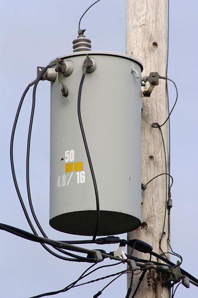
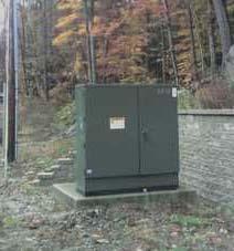
 CHAPTER 4 Distribution Transformers Introduction A transformer is an electrical device that transfers energy from one circuit to another purely by magnetic coupling. Relative motion of the parts of the
KINGS COLLEGE OF ENGINEERING DEPARTMENT OF ELECTRICAL AND ELECTRONICS ENGINEERING QUESTION BANK UNIT I BASIC CIRCUITS ANALYSIS PART A (2-MARKS)
") KINGS COLLEGE OF ENGINEERING DEPARTMENT OF ELECTRICAL AND ELECTRONICS ENGINEERING QUESTION BANK YEAR / SEM : I / II SUBJECT CODE & NAME : EE 1151 CIRCUIT THEORY UNIT I BASIC CIRCUITS ANALYSIS PART A (2-MARKS)
KINGS COLLEGE OF ENGINEERING DEPARTMENT OF ELECTRICAL AND ELECTRONICS ENGINEERING QUESTION BANK YEAR / SEM : I / II SUBJECT CODE & NAME : EE 1151 CIRCUIT THEORY UNIT I BASIC CIRCUITS ANALYSIS PART A (2-MARKS)
13 th Asian Physics Olympiad India Experimental Competition Wednesday, 2 nd May 2012
 13 th Asian Physics Olympiad India Experimental Competition Wednesday, nd May 01 Please first read the following instructions carefully: 1. The time available is ½ hours for each of the two experimental
Question Paper Profile
 I Scheme Question Paper Profile Program Name : Electrical Engineering Program Group Program Code : EE/EP/EU Semester : Third Course Title : Electrical Circuits Max. Marks : 70 Time: 3 Hrs. Instructions:
ECE 2006 University of Minnesota Duluth Lab 11. AC Circuits
 1. Objective AC Circuits In this lab, the student will study sinusoidal voltages and currents in order to understand frequency, period, effective value, instantaneous power and average power. Also, the
Single-Phase Transformation Review
 Single-Phase Transformation Review S T U D E N T M A N U A L March 2, 2005 2 STUDENT TRAINING MANUAL Prerequisites: None Objectives: Given the Construction Standards manual and a formula sheet, you will
Chapter 11. Alternating Current
 Unit-2 ECE131 BEEE Chapter 11 Alternating Current Objectives After completing this chapter, you will be able to: Describe how an AC voltage is produced with an AC generator (alternator) Define alternation,
ET1210: Module 5 Inductance and Resonance
 Part 1 Inductors Theory: When current flows through a coil of wire, a magnetic field is created around the wire. This electromagnetic field accompanies any moving electric charge and is proportional to
cos sin XqIq cos sin V X Consider a simple case ignoring R a and X l d axis q axis V q I q V d I d Approximately, the second item can be ignored:
 Consider a simple case ignoring R a and X l E cos XdId I d E X d cos sin XqIq E E jxdid jxqi q jxdid q jx I d axis q axis I q q d q q I q sin X q d P3 3 I a cos I d I cos abdei cos I sin a q d E Xd Xq
UNIT 1 CIRCUIT ANALYSIS 1 What is a graph of a network? When all the elements in a network is replaced by lines with circles or dots at both ends.
 UNIT 1 CIRCUIT ANALYSIS 1 What is a graph of a network? When all the elements in a network is replaced by lines with circles or dots at both ends. 2 What is tree of a network? It is an interconnected open
ECE 3600 Transformers b
 Transformer basics and ratings A Transformer is two coils of wire that are magnetically coupled. Transformers b Transformers are only useful for AC, which is one of the big reasons electrical power is
Walchand Institute of Technology. Basic Electrical and Electronics Engineering. Transformer
 Walchand Institute of Technology Basic Electrical and Electronics Engineering Transformer 1. What is transformer? explain working principle of transformer. Electrical power transformer is a static device
Outcomes from this session
 Outcomes from this session At the end of this session you should be able to Understand what is meant by the term losses. Iron Losses There are three types of iron losses Eddy current losses Hysteresis
Cork Institute of Technology. Autumn 2008 Electrical Energy Systems (Time: 3 Hours)
") Cork Institute of Technology Bachelor of Science (Honours) in Electrical Power Systems - Award Instructions Answer FIVE questions. (EELPS_8_Y4) Autumn 2008 Electrical Energy Systems (Time: 3 Hours) Examiners:
Cork Institute of Technology Bachelor of Science (Honours) in Electrical Power Systems - Award Instructions Answer FIVE questions. (EELPS_8_Y4) Autumn 2008 Electrical Energy Systems (Time: 3 Hours) Examiners:
Hours / 100 Marks Seat No.
 17415 15162 3 Hours / 100 Seat No. Instructions (1) All Questions are Compulsory. (2) Answer each next main Question on a new page. (3) Illustrate your answers with neat sketches wherever necessary. (4)
PHYS 1442 Section 004 Lecture #15
 PHYS 1442 Section 004 Lecture #15 Monday March 17, 2014 Dr. Andrew Brandt Chapter 21 Generator Transformer Inductance 3/17/2014 1 PHYS 1442-004, Dr. Andrew Brandt Announcements HW8 on Ch 21-22 will be
ELECTRICAL TECHNOLOGY EET 103/4
 ELECTRICAL TECHNOLOGY EET 103/4 Define and analyze the rincile of transformer, its arameters and structure. Describe and analyze Ideal transformer, equivalent circuit, and hasor diagram Calculate and justify
AUTO-TRANSFORMER. This is having only one winding; part of this winding is common to both primary and secondary.
 AUTO-TRANSFORMER This is having only one winding; part of this winding is common to both primary and secondary. In 2-winding transformer both primary and secondary windings are electrically isolated, but
AC Circuits. "Look for knowledge not in books but in things themselves." W. Gilbert ( )
") AC Circuits "Look for knowledge not in books but in things themselves." W. Gilbert (1540-1603) OBJECTIVES To study some circuit elements and a simple AC circuit. THEORY All useful circuits use varying
AC Circuits "Look for knowledge not in books but in things themselves." W. Gilbert (1540-1603) OBJECTIVES To study some circuit elements and a simple AC circuit. THEORY All useful circuits use varying
Code No: R Set No. 1
 Code No: R05220204 Set No. 1 II B.Tech II Semester Supplimentary Examinations, Aug/Sep 2007 ELECTRICAL MACHINES-II (Electrical & Electronic Engineering) Time: 3 hours Max Marks: 80 Answer any FIVE Questions
QUESTION BANK ETE (17331) CM/IF. Chapter1: DC Circuits
 CM/IF. Chapter1: DC Circuits") QUESTION BANK ETE (17331) CM/IF Chapter1: DC Circuits Q1. State & explain Ohms law. Also explain concept of series & parallel circuit with the help of diagram. 3M Q2. Find the value of resistor in fig.
QUESTION BANK ETE (17331) CM/IF Chapter1: DC Circuits Q1. State & explain Ohms law. Also explain concept of series & parallel circuit with the help of diagram. 3M Q2. Find the value of resistor in fig.
Rarely used, problems with unbalanced loads.
 THREE-PHASE TRANSFORMERS Transformers used in three-phase systems may consist of a bank of three single-phase transformers or a single three-phase transformer which is wound on a common magnetic core.
Lab 1: Basic RL and RC DC Circuits
 Name- Surname: ID: Department: Lab 1: Basic RL and RC DC Circuits Objective In this exercise, the DC steady state response of simple RL and RC circuits is examined. The transient behavior of RC circuits
TRANSFORMERS PART A. 2. What is the turns ratio and transformer ratio of transformer? Turns ratio = N2/ N1 Transformer = E2/E1 = I1/ I2 =K
 UNIT II TRANSFORMERS PART A 1. Define a transformer? A transformer is a static device which changes the alternating voltage from one level to another. 2. What is the turns ratio and transformer ratio of
2015 ELECTRICAL SCIENCE
 Summer 2015 ELECTRICAL SCIENCE TIME: THREE HOURS Maximum Marks : 100 Answer five questions, taking ANY TWO from GROUP A, ANY TWO from GROUP B and from GROUP C. All parts of a question (a,b,etc) should
Calculating and compensating for power transformer and cable (or line) losses - standard methods
 losses - standard methods") Guidance Calculating and compensating for power transformer and cable (or line) losses - standard methods Foreword This guidance sets out basic standard methods for calculating electrical loss compensation
Guidance Calculating and compensating for power transformer and cable (or line) losses - standard methods Foreword This guidance sets out basic standard methods for calculating electrical loss compensation
Manuals. Basic Electrical Engineering BE-104
 Manuals Basic Electrical Engineering BE-104 S.NO. EXPERIMENT NAME DATE 1 Measurement of power & power factor in a single phase AC circuit using three Ammeter Method 2 Measurement of active & reactive power
Chapter 16: Mutual Inductance
 Chapter 16: Mutual Inductance Instructor: Jean-François MILLITHALER http://faculty.uml.edu/jeanfrancois_millithaler/funelec/spring2017 Slide 1 Mutual Inductance When two coils are placed close to each
Generator Advanced Concepts
 Generator Advanced Concepts Common Topics, The Practical Side Machine Output Voltage Equation Pitch Harmonics Circulating Currents when Paralleling Reactances and Time Constants Three Generator Curves
WELCOME TO THE LECTURE
 WLCOM TO TH LCTUR ON TRNFORMR Single Phase Transformer Three Phase Transformer Transformer transformer is a stationary electric machine which transfers electrical energy (power) from one voltage level
11. AC-resistances of capacitor and inductors: Reactances.
 11. AC-resistances of capacitor and inductors: Reactances. Purpose: To study the behavior of the AC voltage signals across elements in a simple series connection of a resistor with an inductor and with
Module 1. Introduction. Version 2 EE IIT, Kharagpur
 Module 1 Introduction Lesson 1 Introducing the Course on Basic Electrical Contents 1 Introducing the course (Lesson-1) 4 Introduction... 4 Module-1 Introduction... 4 Module-2 D.C. circuits.. 4 Module-3
Chapter 33. Alternating Current Circuits
 Chapter 33 Alternating Current Circuits C HAP T E O UTLI N E 33 1 AC Sources 33 2 esistors in an AC Circuit 33 3 Inductors in an AC Circuit 33 4 Capacitors in an AC Circuit 33 5 The L Series Circuit 33
Operating principle of a transformer
 Transformers Operating principle of a transformer Transformers are stationary electrical machines which transmit energy from systems with certain current and voltage values into systems with generally
Experiment 9 AC Circuits
 Experiment 9 AC Circuits "Look for knowledge not in books but in things themselves." W. Gilbert (1540-1603) OBJECTIVES To study some circuit elements and a simple AC circuit. THEORY All useful circuits