ESO 210 Introduction to Electrical Engineering
|
|
|
- Christine Burke
- 5 years ago
- Views:
Transcription
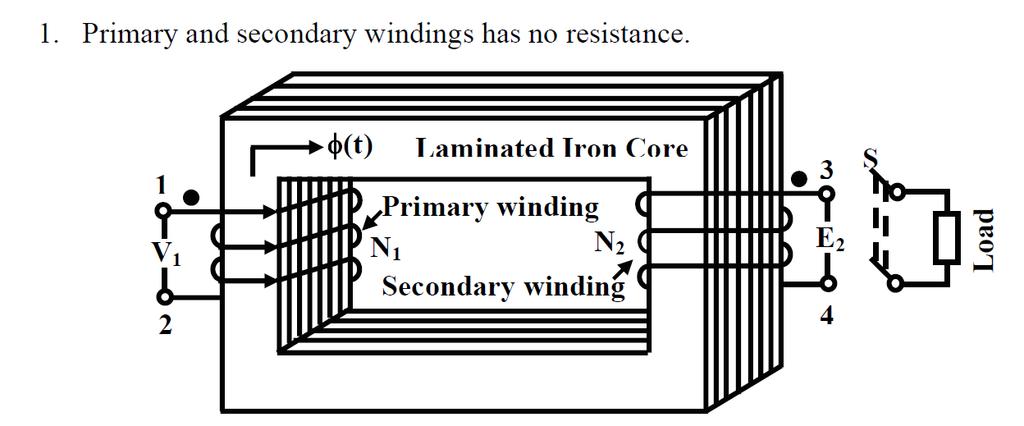
1 ESO 210 Introduction to Electrical Engineering Lecture-19 Magnetic Circuits and Introduction to Transformers
, the mutual inductance is represented by M12.")
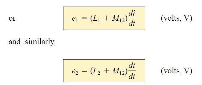
2 2 SERIES CONNECTION OF MUTUALLY COUPLED COILS A mutual term will alter the total inductance of the series combination When referring to the voltage induced across the inductance L1 (or L2) due to the change in flux linkages of the inductance L2 (or L1, respectively), the mutual inductance is represented by M12. This type of subscript notation is particularly important when there are two or more mutual terms.
3 3
4 4
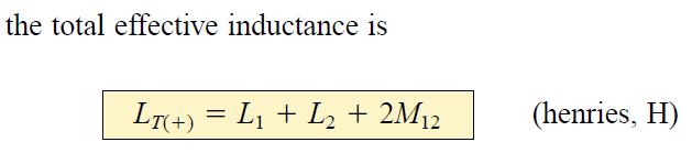
5 5 Finally, The subscript (+) was included to indicate that the mutual terms have a positive sign and are added to the self-inductance values to determine the total inductance. If the coils were wound such as shown in Fig. below, where ø 1 and ø 2 are in opposition, the induced voltages due to the mutual terms would oppose that due to the self-inductance, and the total inductance would be determined by

6 6 The mutual Inductance M 12 can be determined by Above equation is very effective in determining the mutual inductance between two coils. It states that the mutual inductance is equal to one-quarter the difference between the total inductance with a positive and negative mutual effect. It should be clear that the mutual inductance will directly affect the magnitude of the voltage induced across a coil since it will determine the net inductance of the coil. On a network schematic where it is inconvenient to indicate the windings and the flux path, a system of dots is employed that will determine whether the mutual terms are to be positive or negative. The dot convention is shown in Fig. on the next slide for the series coils


7 The dot convention is shown in Fig. below for the series coils 7


8 8? If the current through each of the mutually coupled coils is going away from the dot as it passes through the coil, the mutual term will be positive, as shown for the case in Fig. above. If the arrow indicating current direction through the coil is leaving the dot for one coil and entering the dot for the other, the mutual term is negative. The dot convention also reveals the polarity of the induced voltage across the mutually coupled coil. If the reference direction for the current in a coil leaves the dot, the polarity at the dot for the induced voltage of the mutually coupled coil is positive.
9 EXAMPLE: Find the total inductance of the series coils of Fig. below. 9
10 10
11 EXAMPLE: Write the mesh equations for the transformer network in Fig. shown below. 11
12 12

13 What is this? 13
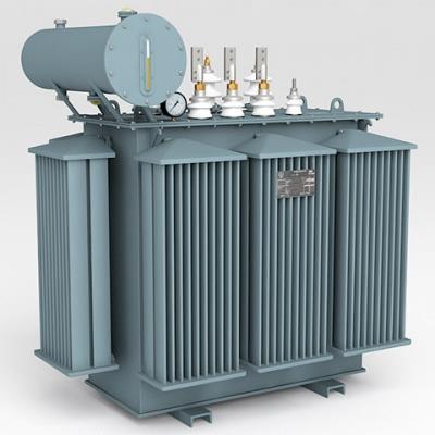
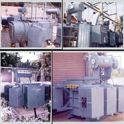
14 14
15 15
16 16

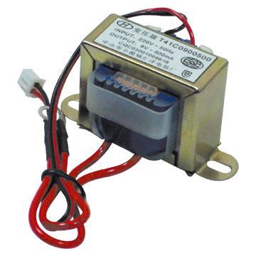
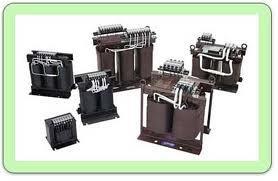
17 17 Transformers are an integral part in any modern power system
18 18


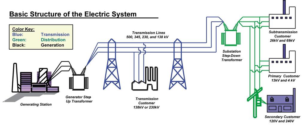
19 19 Transformers: The most important components of any power system. Basically change the level of voltages from one value to the other at constant frequency. Being a static machine the efficiency of a transformer could be as high as 99%. (Typically more than 95%) Big generating stations are located at hundreds or more km away from the load center (where the power will be actually consumed). Since long transmission lines carry the power to the load centre from the generating stations. Generator is a rotating machines and the level of voltage at which it generates power is limited to several kilo volts only a typical value is 11 kv.
20 20
21 21 To transmit large amount of power (several thousands of mega watts) at this voltage level means large amount of current has to flow through the transmission lines. The cross sectional area of the conductor of the lines accordingly should be large. Hence cost involved in transmitting a given amount of power rises many folds. Not only that, the transmission lines has their own resistances. This huge amount of current will cause tremendous amount of power loss or I 2 r loss in the lines. This loss will simply heat the lines and becomes a wasteful energy. In other words, efficiency of transmission becomes poor and cost involved is high without Transformers. The poor efficiency problems may be addressed if we could transmit power at a very high voltage say, at 200 kv or 400 kv or even higher at 800 kv.
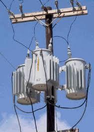
22 22 Since, a generator is incapable of generating voltage at these level due to its own practical limitation. The solution to this problem is to use an appropriate step-up transformer at the generating station to bring the transmission voltage level at the desired value. Obviously when power reaches the load centre, one has to step down the voltage to suitable and safe values by using transformers. Thus transformers are an integral part in any modern power system. Transformers are located in places called substations. In cities or towns you must have noticed transformers are installed on poles these are called pole mounted distribution transformers. These type of transformers change voltage level typically from 3-phase, 6 kv to 3-phase 440 V line to line.
23 23

24 Transformer 24
25 25
26 26
27 27
28 28
29 29
Transformers. Dr. Gamal Sowilam
 Transformers Dr. Gamal Sowilam OBJECTIVES Become familiar with the flux linkages that exist between the coils of a transformer and how the voltages across the primary and secondary are established. Understand
By Gill ( ) PDF created with FinePrint pdffactory trial version
 PDF created with FinePrint pdffactory trial version") By Gill (www.angelfire.com/al4/gill ) 1 Introduction One of the main reasons of adopting a.c. system instead of d.c. for generation, transmission and distribution of electrical power is that alternatin
By Gill (www.angelfire.com/al4/gill ) 1 Introduction One of the main reasons of adopting a.c. system instead of d.c. for generation, transmission and distribution of electrical power is that alternatin
Chapter 16: Mutual Inductance
 Chapter 16: Mutual Inductance Instructor: Jean-François MILLITHALER http://faculty.uml.edu/jeanfrancois_millithaler/funelec/spring2017 Slide 1 Mutual Inductance When two coils are placed close to each
I p = V s = N s I s V p N p
 UNIT G485 Module 1 5.1.3 Electromagnetism 11 For an IDEAL transformer : electrical power input = electrical power output to the primary coil from the secondary coil Primary current x primary voltage =
Unit-4. Magnetic Circuits
 Unit-4 Magnetic Circuits Topics to be Discussed Magnetic Coupling. Coefficient of Coupling (k). Sign of Mutual Voltage. Dot Convention. September 9, 0 Magnetic Circuits Magnetically Coupled Circuits A
13. Magnetically Coupled Circuits
 13. Magnetically Coupled Circuits The change in the current flowing through an inductor induces (creates) a voltage in the conductor itself (self-inductance) and in any nearby conductors (mutual inductance)
Faraday Laws of Electromagnetic Induction CLIL LESSON
 Faraday Laws of Electromagnetic Induction CLIL LESSON Experimental trials Michael Faraday-1931 This law shows the relationship between electric circuit and magnetic field A coil is connected to a galvanometer
CHAPTER 2. Transformers. Dr Gamal Sowilam
 CHAPTER Transformers Dr Gamal Sowilam Introduction A transformer is a static machine. It is not an energy conversion device, it is indispensable in many energy conversion systems. A transformer essentially
1 K Hinds 2012 TRANSFORMERS
 1 K Hinds 2012 TRANSFORMERS A transformer changes electrical energy of a given voltage into electrical energy at a different voltage level. It consists of two coils which are not electrically connected,
TRANSFORMER OPERATION
 Chapter 3 TRANSFORMER OPERATION 1 A transformer is a static device (no moving parts) used to transfer energy from one AC circuit to another. This transfer of energy may involve an increase or decrease
PHYS 1441 Section 001 Lecture #22 Wednesday, Nov. 29, 2017
 PHYS 1441 Section 001 Lecture #22 Chapter 29:EM Induction & Faraday s Law Transformer Electric Field Due to Changing Magnetic Flux Chapter 30: Inductance Mutual and Self Inductance Energy Stored in Magnetic
Cornerstone Electronics Technology and Robotics Week 32 Transformers
 Cornerstone Electronics Technology and Robotics Week 32 Transformers Administration: o Prayer o Turn in quiz Electricity and Electronics, Section 12.1, Transformer Theory: o A transformer is a device that
PHYS 1444 Section 501 Lecture #20
 PHYS 1444 Section 501 Lecture #0 Monday, Apr. 17, 006 Transformer Generalized Faraday s Law Inductance Mutual Inductance Self Inductance Inductor Energy Stored in the Magnetic Field 1 Announcements Quiz
3.1.Introduction. Synchronous Machines
 3.1.Introduction Synchronous Machines A synchronous machine is an ac rotating machine whose speed under steady state condition is proportional to the frequency of the current in its armature. The magnetic
Trade of Electrician. Introduction to AC
 Trade of Electrician Standards Based Apprenticeship Introduction to AC Phase 2 Module No. 2.1 Unit No. 2.1.9 COURSE NOTES Created by Gerry Ryan - Galway TC Revision 1. April 2000 by Gerry Ryan - Galway
TRANSFORMER THEORY. Mutual Induction
 Transformers Transformers are used extensively for AC power transmissions and for various control and indication circuits. Knowledge of the basic theory of how these components operate is necessary to
Module 7. Transformer. Version 2 EE IIT, Kharagpur
 Module 7 Transformer Lesson 3 Ideal Transformer Contents 3 Ideal Transformer (Lesson: 3) 4 3. Goals of the lesson 4 3. Introduction.. 5 3.. Principle of operation.. 5 3.3 Ideal Transformer.. 6 3.3. Core
ESO 210 Introduction to Electrical Engineering
 ESO 210 Introduction to Electrical Engineering Lecture-12 Three Phase AC Circuits Three Phase AC Supply 2 3 In general, three-phase systems are preferred over single-phase systems for the transmission
Transformers. Objectives
 Transformers Objectives Explain mutual inductance Describe how a transformer is constructed and how it works Explain how a step-up transformer works Explain how a step-down transformer works Discuss the
CHAPTER 8: ELECTROMAGNETISM
 CHAPTER 8: ELECTROMAGNETISM 8.1: MAGNETIC EFFECT OF A CURRENT-CARRYING CONDUCTOR Electromagnets 1. Conductor is a material that can flow.. 2. Electromagnetism is the study of the relationship between.and..
Chapter 13 Magnetically Coupled Circuits. Chapter Objectives:
 Chapter 13 Magnetically Coupled Circuits Chapter Objectives: Understand magnetically coupled circuits. Learn the concept of mutual inductance. Be able to determine energy in a coupled circuit. Learn how
In this lecture. Electromagnetism. Electromagnetism. Oersted s Experiment. Electricity & magnetism are different aspects of the same basic phenomenon:
 In this lecture Electromagnetism Electromagnetic Effect Electromagnets Electromechanical Devices Transformers Electromagnetic Effect Electricity & magnetism are different aspects of the same basic phenomenon:
PHYSICS VCE UNITS 3&4 DIAGNOSTIC TOPIC TESTS 2017
 PHYSICS VCE UNITS 3&4 DIAGNOSTIC TOPIC TESTS 2017 TEST 3: TOTAL 45 MARKS (45 MINUTES) Student s Name: Teacher s Name: Directions to students Write your name and your teacher s name in the spaces provided
Power System Analysis Prof. A. K. Sinha Department of Electrical Engineering Indian institute of Technology, Kharagpur
 Power System Analysis Prof. A. K. Sinha Department of Electrical Engineering Indian institute of Technology, Kharagpur Lecture - 10 Transmission Line Steady State Operation Voltage Control (Contd.) Welcome
N I N LI I. I t. (Note how L is independent of the current I.)
") UNIT- IV MAGNETICALLY COUPLED CIRCUITS Magnetically Coupled Circuits: Self inductance - Mutual inductance - Dot rule - Coefficient of coupling - Analysis of multi winding coupled circuits - Series, Parallel
UNIT- IV MAGNETICALLY COUPLED CIRCUITS Magnetically Coupled Circuits: Self inductance - Mutual inductance - Dot rule - Coefficient of coupling - Analysis of multi winding coupled circuits - Series, Parallel
Note on Posted Slides
 Note on Posted Slides These are the slides that I intended to show in class on Tue. Mar. 25, 2014. They contain important ideas and questions from your reading. Due to time constraints, I was probably
PHYS 1444 Section 003 Lecture #19
 PHYS 1444 Section 003 Lecture #19 Monday, Nov. 14, 2005 Electric Generators DC Generator Eddy Currents Transformer Mutual Inductance Today s homework is homework #10, due noon, next Tuesday!! 1 Announcements
AC generator theory. Resources and methods for learning about these subjects (list a few here, in preparation for your research):
:") AC generator theory This worksheet and all related files are licensed under the Creative Commons Attribution License, version 1.0. To view a copy of this license, visit http://creativecommons.org/licenses/by/1.0/,
AC generator theory This worksheet and all related files are licensed under the Creative Commons Attribution License, version 1.0. To view a copy of this license, visit http://creativecommons.org/licenses/by/1.0/,
12/6/2011. Electromagnetic Induction. Electromagnetic Induction and Electromagnetic Waves. Checking Understanding. Magnetic Flux. Lenz s Law.
 Electromagnetic Induction and Electromagnetic Waves Topics: Electromagnetic induction Lenz s law Faraday s law The nature of electromagnetic waves The spectrum of electromagnetic waves Electromagnetic
Unit 3 Magnetism...21 Introduction The Natural Magnet Magnetic Polarities Magnetic Compass...21
 Chapter 1 Electrical Fundamentals Unit 1 Matter...3 Introduction...3 1.1 Matter...3 1.2 Atomic Theory...3 1.3 Law of Electrical Charges...4 1.4 Law of Atomic Charges...4 Negative Atomic Charge...4 Positive
Basics of Electricity
 Basics of Electricity A quickstep Online Course Siemens industry, Inc. www.usa.siemens.com/step Trademarks Siemens is a trademark of Siemens AG. Product names mentioned may be trademarks or registered
Chapter 24. Alternating Current Circuits
 Chapter 24 Alternating Current Circuits Objective of Lecture Generators and Motors Inductance RL Circuits (resistance and inductance) Transformers AC REMINDER: WORK ON THE EXAMPLES Read physics in perspective
WELCOME TO THE LECTURE
 WLCOM TO TH LCTUR ON TRNFORMR Single Phase Transformer Three Phase Transformer Transformer transformer is a stationary electric machine which transfers electrical energy (power) from one voltage level
UNIVERSITY OF TECHNOLOGY By: Fadhil A. Hasan ELECTRICAL MACHINES
 UNIVERSITY OF TECHNOLOGY DEPARTMENT OF ELECTRICAL ENGINEERING Year: Second 2016-2017 By: Fadhil A. Hasan ELECTRICAL MACHINES І Module-II: AC Transformers o Single phase transformers o Three-phase transformers
Trade of Electrician. The Transformer
 Trade of Electrician Standards Based Apprenticeship The Transformer Phase 2 Module No. 2.1 Unit No. 2.1.10 COURSE NOTES Created by Gerry Ryan - Galway TC Revision 1 April 2000 by Gerry Ryan - Galway TC
Walchand Institute of Technology. Basic Electrical and Electronics Engineering. Transformer
 Walchand Institute of Technology Basic Electrical and Electronics Engineering Transformer 1. What is transformer? explain working principle of transformer. Electrical power transformer is a static device
Electrical Theory 2 Lessons for Fall Semester:
 Electrical Theory 2 Lessons for Fall Semester: Lesson 1 Magnetism Lesson 2 Introduction to AC Theory Lesson 3 Lesson 4 Capacitance and Capacitive Reactance Lesson 5 Impedance and AC Circuits Lesson 6 AC
Electric Circuits II Magnetically Coupled Circuits. Dr. Firas Obeidat
 Electric Circuits II Magnetically Coupled Circuits Dr. Firas Obeidat 1 Table of contents 1 Mutual Inductance 2 Dot Convention 3 Analyze Circuits Involving Mutual Inductance 4 Energy in a Coupled Circuit
Review: Lecture 9. Instantaneous and Average Power. Effective or RMS Value. Apparent Power and Power Factor. Complex Power. Conservation of AC Power
 Review: Lecture 9 Instantaneous and Average Power p( t) VmI m cos ( v i ) VmI m cos ( t v i ) Maximum Average Power Transfer Z L R L jx Effective or RMS Value I rms I m L R P * TH Apparent Power and Power
Inductance in DC Circuits
 Inductance in DC Circuits Anurag Srivastava Concept: Inductance is characterized by the behavior of a coil of wire in resisting any change of electric current through the coil. Arising from Faraday's law,
CHAPTER 13 REVIEW. Knowledge. Understanding
 CHAPTER 13 REVIEW K/U Knowledge/Understanding T/I Thinking/Investigation C Communication A Application Knowledge For each question, select the best answer from the four alternatives. 1. Which of the following
EE 42/100 Lecture 16: Inductance. Rev B 3/15/2010 (8:55 PM) Prof. Ali M. Niknejad
 Prof. Ali M. Niknejad") A. M. Niknejad University of California, Berkeley EE 100 / 42 Lecture 16 p. 1/23 EE 42/100 Lecture 16: Inductance ELECTRONICS Rev B 3/15/2010 (8:55 PM) Prof. Ali M. Niknejad University of California, Berkeley
A. M. Niknejad University of California, Berkeley EE 100 / 42 Lecture 16 p. 1/23 EE 42/100 Lecture 16: Inductance ELECTRONICS Rev B 3/15/2010 (8:55 PM) Prof. Ali M. Niknejad University of California, Berkeley
Transformers 21.1 INTRODUCTION 21.2 MUTUAL INDUCTANCE
 21 Transformers 21.1 INTRODUCTION Chapter 12 discussed the self-inductance of a coil. We shall now examine the mutual inductance that exists between coils of the same or different dimensions. Mutual inductance
PHYS 1442 Section 004 Lecture #15
 PHYS 1442 Section 004 Lecture #15 Monday March 17, 2014 Dr. Andrew Brandt Chapter 21 Generator Transformer Inductance 3/17/2014 1 PHYS 1442-004, Dr. Andrew Brandt Announcements HW8 on Ch 21-22 will be
TRANSFORMERS INTRODUCTION
 Tyco Electronics Corporation Crompton Instruments 1610 Cobb International Parkway, Unit #4 Kennesaw, GA 30152 Tel. 770-425-8903 Fax. 770-423-7194 TRANSFORMERS INTRODUCTION A transformer is a device that
Introduction. Inductors in AC Circuits.
 Module 3 AC Theory What you ll learn in Module 3. Section 3.1 Electromagnetic Induction. Magnetic Fields around Conductors. The Solenoid. Section 3.2 Inductance & Back e.m.f. The Unit of Inductance. Factors
CHAPTER 5 CONCEPTS OF ALTERNATING CURRENT
 CHAPTER 5 CONCEPTS OF ALTERNATING CURRENT INTRODUCTION Thus far this text has dealt with direct current (DC); that is, current that does not change direction. However, a coil rotating in a magnetic field
Preface...x Chapter 1 Electrical Fundamentals
 Preface...x Chapter 1 Electrical Fundamentals Unit 1 Matter...3 Introduction...3 1.1 Matter...3 1.2 Atomic Theory...3 1.3 Law of Electrical Charges...4 1.4 Law of Atomic Charges...5 Negative Atomic Charge...5
Alternating Current Page 1 30
 Alternating Current 26201 11 Page 1 30 Calculate the peak and effective voltage of current values for AC Calculate the phase relationship between two AC waveforms Describe the voltage and current phase
PESIT Bangalore South Campus Hosur road, 1km before Electronic City, Bengaluru -100 Department of Electronics & Communication Engineering
 INTERNAL ASSESSMENT TEST 3 Date : 15/11/16 Marks: 0 Subject & Code: BASIC ELECTRICAL ENGINEERING -15ELE15 Sec : F,G,H,I,J,K Name of faculty : Mrs.Hema, Mrs.Dhanashree, Mr Nagendra, Mr.Prashanth Time :
PROBLEMS. Figure13.74 For Prob Figure13.72 For Prob Figure13.75 For Prob Figure13.73 For Prob Figure13.76 For Prob
 CHAPTER 13 Magnetically Coupled Circuits 571 13.9 In order to match a source with internal impedance of 500 to a 15- load, what is needed is: (a) step-up linear transformer (b) step-down linear transformer
UNIT 1 CIRCUIT ANALYSIS 1 What is a graph of a network? When all the elements in a network is replaced by lines with circles or dots at both ends.
 UNIT 1 CIRCUIT ANALYSIS 1 What is a graph of a network? When all the elements in a network is replaced by lines with circles or dots at both ends. 2 What is tree of a network? It is an interconnected open
Electromagnetic Induction. Transformer 5/16/11
 ransformer Content 23.1 Principles of electromagnetic induction 23.2 he a.c. generator 23.3 he transformer Learning Outcomes Candidates should be able to: (a) describe an experiment which shows that a
Power Electronics. Prof. B. G. Fernandes. Department of Electrical Engineering. Indian Institute of Technology, Bombay.
 Power Electronics Prof. B. G. Fernandes Department of Electrical Engineering Indian Institute of Technology, Bombay Lecture - 28 So far we have studied 4 different DC to DC converters. They are; first
Combined analytical and FEM method for prediction of synchronous generator no-load voltage waveform
 Combined analytical and FEM method for prediction of synchronous generator no-load voltage waveform 1. INTRODUCTION It is very important for the designer of salient pole synchronous generators to be able
Transformers. gpmacademics.weebly.com
 TRANSFORMERS Syllabus: Principles of operation, Constructional Details, Losses and efficiency, Regulation of Transformer, Testing: OC & SC test. TRANSFORMER: It is a static device which transfers electric
ESO 210 Introduction to Electrical Engineering
 ESO 210 Introduction to Electrical Engineering Lecture-14 Three Phase AC Circuits 2 THE -CONNECTED GENERATOR If we rearrange the coils of the generator as shown in Fig. below the system is referred to
Bakiss Hiyana binti Abu Bakar JKE, POLISAS BHAB
 1 Bakiss Hiyana binti Abu Bakar JKE, POLISAS 1. Explain AC circuit concept and their analysis using AC circuit law. 2. Apply the knowledge of AC circuit in solving problem related to AC electrical circuit.
THE SINUSOIDAL WAVEFORM
 Chapter 11 THE SINUSOIDAL WAVEFORM The sinusoidal waveform or sine wave is the fundamental type of alternating current (ac) and alternating voltage. It is also referred to as a sinusoidal wave or, simply,
EEE3441 Electrical Machines Department of Electrical Engineering. Lecture. Basic Operating Principles of Transformers
 Department of Electrical Engineering Lecture Basic Operating Principles of Transformers In this Lecture Basic operating principles of following transformers are introduced Single-phase Transformers Three-phase
Types of Generators ACCORDING TO EXCITATION
 Types of Generators ACCORDING TO EXCITATION Separately Excited DC Generator A dc generator whose field magnet winding is supplied from an independent external d.c. source (e.g., a battery etc.) Separately
17-2 Electromagnetic Induction
 17-2 Electromagnetic Induction Magnetic Flux and Induced Voltage Flux: The number of magnetic field lines passing through a given area. flux (area)(perpendicular component of the magnetic field) or AB
The topics in this unit are:
 The topics in this unit are: 1 Static electricity 2 Repulsion and attraction 3 Electric circuits 4 Circuit symbols 5 Currents 6 Resistance 7 Thermistors and light dependent resistors 8 Series circuits
Radar. Radio. Electronics. Television. .104f 4E011 UNITED ELECTRONICS LABORATORIES LOUISVILLE
 Electronics Radio Television.104f Radar UNITED ELECTRONICS LABORATORIES LOUISVILLE KENTUCKY REVISED 1967 4E011 1:1111E111611 COPYRIGHT 1956 UNITED ELECTRONICS LABORATORIES POWER SUPPLIES ASSIGNMENT 23
3. What is hysteresis loss? Also mention a method to minimize the loss. (N-11, N-12)
") DHANALAKSHMI COLLEGE OF ENGINEERING, CHENNAI DEPARTMENT OF ELECTRICAL AND ELECTRONICS ENGINEERING EE 6401 ELECTRICAL MACHINES I UNIT I : MAGNETIC CIRCUITS AND MAGNETIC MATERIALS Part A (2 Marks) 1. List
DHANALAKSHMI COLLEGE OF ENGINEERING, CHENNAI DEPARTMENT OF ELECTRICAL AND ELECTRONICS ENGINEERING EE 6401 ELECTRICAL MACHINES I UNIT I : MAGNETIC CIRCUITS AND MAGNETIC MATERIALS Part A (2 Marks) 1. List
Module 9. DC Machines. Version 2 EE IIT, Kharagpur
 Module 9 DC Machines Lesson 35 Constructional Features of D.C Machines Contents 35 D.C Machines (Lesson-35) 4 35.1 Goals of the lesson. 4 35.2 Introduction 4 35.3 Constructional Features. 4 35.4 D.C machine
Copper and Electricity: Transformers and. the Grid. Transformers
 PHYSICS Copper and Electricity: Transformers and 16-18 YEARS the Grid Transformers Using transformers We use transformers to change the size of a voltage. We can step the voltage down from a high voltage
VARIABLE INDUCTANCE TRANSDUCER
 VARIABLE INDUCTANCE TRANSDUCER These are based on a change in the magnetic characteristic of an electrical circuit in response to a measurand which may be displacement, velocity, acceleration, etc. 1.
Look over Chapter 31 sections 1-4, 6, 8, 9, 10, 11 Examples 1-8. Look over Chapter 21 sections Examples PHYS 2212 PHYS 1112
 PHYS 2212 Look over Chapter 31 sections 1-4, 6, 8, 9, 10, 11 Examples 1-8 PHYS 1112 Look over Chapter 21 sections 11-14 Examples 16-18 Good Things To Know 1) How AC generators work. 2) How to find the
Intermediate Physics PHYS102
 Intermediate Physics PHYS102 Dr Richard H. Cyburt Assistant Professor of Physics My office: 402c in the Science Building My phone: (304) 384-6006 My email: rcyburt@concord.edu My webpage: www.concord.edu/rcyburt
A Practical Guide to Free Energy Devices
 A Practical Guide to Free Energy Devices Device Patent No 30: Last updated: 24th June 2007 Author: Patrick J. Kelly This patent shows a method of altering a standard electrical generator intended to be
APPLICATION NOTE - 018
 APPLICATION NOTE - 018 Power Transformers Background Power Transformers are used within an AC power distribution systems to increase or decrease the operating voltage to achieve the optimum transmission
AUTO-TRANSFORMER. This is having only one winding; part of this winding is common to both primary and secondary.
 AUTO-TRANSFORMER This is having only one winding; part of this winding is common to both primary and secondary. In 2-winding transformer both primary and secondary windings are electrically isolated, but
DESIGN AND CONSTRUCTION OF 1500VA VARIABLE OUTPUT STEP DOWN TRANSFORMER
 DESIGN AND CONSTRUCTION OF 1500VA VARIABLE OUTPUT STEP DOWN TRANSFORMER OGUNDARE AYOADE B., OMOGOYE O. SAMUEL & OLUWASANYA OMOTAYO J. Department of Electrical/Electronic engineering, Lagos State Polytechnic,
ECE 241L Fundamentals of Electrical Engineering. Experiment 8 A-C Transformer, Magnetization & Hysteresis
 ECE 241L Fundamentals of Electrical Engineering Experiment 8 A-C Transformer, Magnetization & Hysteresis A. Objectives: I. Measure leakage inductance and resistance loss II. Measure magnetization inductance
Electrical Theory. Power Principles and Phase Angle. PJM State & Member Training Dept. PJM /22/2018
 Electrical Theory Power Principles and Phase Angle PJM State & Member Training Dept. PJM 2018 Objectives At the end of this presentation the learner will be able to: Identify the characteristics of Sine
TRANSFORMERS PART A. 2. What is the turns ratio and transformer ratio of transformer? Turns ratio = N2/ N1 Transformer = E2/E1 = I1/ I2 =K
 UNIT II TRANSFORMERS PART A 1. Define a transformer? A transformer is a static device which changes the alternating voltage from one level to another. 2. What is the turns ratio and transformer ratio of
UNIT II MEASUREMENT OF POWER & ENERGY
 UNIT II MEASUREMENT OF POWER & ENERGY Dynamometer type wattmeter works on a very simple principle which is stated as "when any current carrying conductor is placed inside a magnetic field, it experiences
Name: Lab Partner: Section: The purpose of this lab is to study induction. Faraday s law of induction and Lenz s law will be explored. B = B A (8.
 Chapter 8 Induction - Faraday s Law Name: Lab Partner: Section: 8.1 Purpose The purpose of this lab is to study induction. Faraday s law of induction and Lenz s law will be explored. 8.2 Introduction It
Chapter 7. Copyright The McGraw-Hill Companies, Inc. Permission required for reproduction or display.
 Chapter 7 Copyright The McGraw-Hill Companies, Inc. Permission required for reproduction or display. Learning Objectives 1. Understand the meaning of instantaneous and average power, master AC power notation,
EE 221 Circuits II. Chapter 13 Magnetically Coupled Circuits
 EE Circuits II Chapter 3 Magnetically Coupled Circuits Magnetically Coupled Circuits 3. What is a transformer? 3. Mutual Inductance 3.3 Energy in a Coupled Circuit 3.4 inear Transformers 3.5 Ideal Transformers
A Practical Guide to Free Energy Devices
 A Practical Guide to Free Energy Devices Part PatD21: Last updated: 29th November 2006 Author: Patrick J. Kelly This patent covers a device which is claimed to have a greater output power than the input
SECTION 3 BASIC AUTOMATIC CONTROLS UNIT 12 BASIC ELECTRICITY AND MAGNETISM. Unit Objectives. Unit Objectives 2/29/2012
 SECTION 3 BASIC AUTOMATIC CONTROLS UNIT 12 BASIC ELECTRICITY AND MAGNETISM Unit Objectives Describe the structure of an atom. Identify atoms with a positive charge and atoms with a negative charge. Explain
Electrical Equipment - Course The student must be able to: 1.1 State the purpose of electrical metering. (0) VT Primary and Secondary Fuses,
 VT Primary and Secondary Fuses,") Electrical Equipment - Course 230.2 ELECTRICAL METERING: PART 1 VOLTAGE AND CURRENT TRANSFORMERS 1. OBJECTIVE The student must be able to: 1.1 State the purpose of electrical metering. 1.2 State the purpose
Electrical Equipment - Course 230.2 ELECTRICAL METERING: PART 1 VOLTAGE AND CURRENT TRANSFORMERS 1. OBJECTIVE The student must be able to: 1.1 State the purpose of electrical metering. 1.2 State the purpose
Questions on Electromagnetism
 Questions on Electromagnetism 1. The dynamo torch, Figure 1, is operated by successive squeezes of the handle. These cause a permanent magnet to rotate within a fixed coil of wires, see Figure 2. Harder
In an unmagnetized piece of iron, the atoms are arranged in domains. In each domain the atoms are aligned, but the domains themselves are random.
 4/7 Properties of the Magnetic Force 1. Perpendicular to the field and velocity. 2. If the velocity and field are parallel, the force is zero. 3. Roughly (field and vel perp), the force is the product
Transformers. ELG3311: Habash,
 Transformers A transformer is a device that changes AC electric power at one voltage level to AC electric power at another voltage level through the action of magnetic field. t consists of two or more
6. List two possible arrangements of a Yconnection and give one application
 OBJECTIVES PI 26.35-1 Electrical Equipment - Course PI 30.2 THREE PHASE SYSTEMS On completion of this module the student will be able to: 1. In a few sentences explain how three phase voltages are produced
GEOS / ENST Problem set #Grid Due: Tues. May 17
 GEOS 24705 / ENST 24705 Problem set #Grid Due: Tues. May 17 Problem 1: Three-phase power transmission The standard means by which electricity is generated and transmitted in the U.S. is as 3- phase AC
Table of Contents. Introduction...2 Conductors and Insulators...3 Current, Voltage, and Resistance...6
 Table of Contents Introduction...2 Conductors and Insulators...3 Current, Voltage, and Resistance...6 Ohm s Law... 11 DC Circuits... 13 Magnetism...20 Alternating Current...23 Inductance and Capacitance...30
Table of Contents. Table of Figures. Table of Tables
 Abstract The aim of this report is to investigate and test a transformer and check if it is good to use by doing the following tests continuity test, insulation test, polarity test, open circuit test,
Module 1. Introduction. Version 2 EE IIT, Kharagpur
 Module 1 Introduction Lesson 1 Introducing the Course on Basic Electrical Contents 1 Introducing the course (Lesson-1) 4 Introduction... 4 Module-1 Introduction... 4 Module-2 D.C. circuits.. 4 Module-3
CHAPTER 2. Basic Concepts, Three-Phase Review, and Per Unit
 CHAPTER 2 Basic Concepts, Three-Phase Review, and Per Unit 1 AC power versus DC power DC system: - Power delivered to the load does not fluctuate. - If the transmission line is long power is lost in the
PESIT Bangalore South Campus Hosur road, 1km before Electronic City, Bengaluru -100 Department of Electronics & Communication Engineering
 CONTINUOUS INTERNAL EVALUATION TEST -1 Date : 27/2/2018 Marks:60 Subject & Code : Basic Electrical Engineering, 17ELE25 Section: A,B,C,D,E Time : 8:30 am 11:30 a.m Name of faculty: Mrs. Dhanashree Bhate,
Electrical Circuits and Systems
 Electrical Circuits and Systems Macmillan Education Basis Books in Electronics Series editor Noel M. Morris Digital Electronic Circuits and Systems Linear Electronic Circuits and Systems Electronic Devices
~=E.i!=h. Pre-certification Transformers
 7 Transformers Section 26 of the electrical code governs the use and installations of transformers. A transformer is a static device used to transfer energy from one alternating current circuit to another.
Transformers 1 of 25 Boardworks Ltd 2016
 Transformers 1 of 25 Boardworks Ltd 2016 Transformers 2 of 25 Boardworks Ltd 2016 Linking circuits with magnetism 3 of 25 Boardworks Ltd 2016 Transformers 4 of 25 Boardworks Ltd 2016 Power can be transferred
Three-Phase Induction Motors. By Sintayehu Challa ECEg332:-Electrical Machine I
 Three-Phase Induction Motors 1 2 3 Classification of AC Machines 1. According to the type of current Single Phase and Three phase 2. According to Speed Constant Speed, Variable Speed and Adjustable Speed
Electrical Machines (EE-343) For TE (ELECTRICAL)
 For TE (ELECTRICAL)") PRACTICALWORKBOOK Electrical Machines (EE-343) For TE (ELECTRICAL) Name: Roll Number: Year: Batch: Section: Semester: Department: N.E.D University of Engineering &Technology, Karachi Electrical Machines
PRACTICALWORKBOOK Electrical Machines (EE-343) For TE (ELECTRICAL) Name: Roll Number: Year: Batch: Section: Semester: Department: N.E.D University of Engineering &Technology, Karachi Electrical Machines
Power. Power is the rate of using energy in joules per second 1 joule per second Is 1 Watt
 3 phase Power All we need electricity for is as a source of transport for energy. We can connect to a battery, which is a source of stored energy. Or we can plug into and electric socket at home or in