N I N LI I. I t. (Note how L is independent of the current I.)
|
|
|
- Rosalind Fletcher
- 5 years ago
- Views:
Transcription
1 UNIT- IV MAGNETICALLY COUPLED CIRCUITS Magnetically Coupled Circuits: Self inductance - Mutual inductance - Dot rule - Coefficient of coupling - Analysis of multi winding coupled circuits - Series, Parallel connection of coupled inductors - Single tuned and double tuned coupled circuits 4.1 Self-inductance If the current through a coil is altered then the flux through that coil also changes, and this will induce an e.m.f. in the coil itself. This effect is known self-induction and the property of the coil is the selfinductance (L) of the coil, usually abbreviated as the inductance. A current-carrying coil produces a magnetic field that links its own turns. If the current in the coil changes the amount of magnetic flux linking the coil changes and, by Faraday s law, an emf is produced in the coil. This emf is called a self-induced emf. Let the coil have N turns. Assume that the same amount of magnetic flux links each turn of the coil. The net flux linking the coil is then N. This net flux is proportional to the magnetic field, which, in turn, is proportional to the current I in the coil. Thus we can write N I. This proportionality can be turned into an equation by introducing a constant. Call this constant L, the self-inductance (or simply inductance) of the coil N N LI or L I As with mutual inductance, the unit of self-inductance is the henry. The self-induced emf can now be calculated using Faraday s law E N LI I N L t t t t I E L t The above formula is the emf due to self-induction. Formula for the self-inductance of a solenoid of N turns, length l, and cross-sectional area A. Assume that the solenoid carries a current I. Then the magnetic flux in the solenoid is NI N N NI 0 A. L 0 A l I I l 2 N 2 N L 0 A or L 0n Al where n. l l (Note how L is independent of the current I.) The energy is used to produce the magnetic field in and around the coil. If the current is suddenly interrupted a spark may occur as the energy is dissipated. Self-inductance can be a problem in circuits, where the breaking of the circuit can induce a large e.m.f., and so the switches maybe immersed in oil to quench the arc. Alternatively a capacitor may be connected across the terminals to slow down the decay of current and so reduce the induced e.m.f. 58
2 Example Calculate the energy stored in the coil given in the previous example (L = 1.25 mh) if the current through it is 0.5 A. Energy stored = ½ LI 2 = 1.25x10-3 x0.5 2 = 0.31x10⁻³ J 4.2 Growth and decay of current in an inductor When a battery of e.m.f E is connected across a resistor and an inductor in series the current does not rise to its final value instantaneously. There is a rise time that is due to the back e.m.f in the inductor and the resistance and inductance of the circuit. R E L Fig 4.1 Inductor circuit I = E/R(1 e -t/(l/r) ) A similar argument can be applied to the decay of current when the cell is disconnected, the equation in this case being - L di/dt = IR with solution: Current E/R(1- Final I = E/R(e -t/(l/r) ) L/R Time (t) Example A coil with a self-inductance of 1.25 mh (see previous examples) is connected to a resistor of 24 and a supply of 12 V. Calculate the time taken for the current to rise to 0.45A. (Final d.c current would be 0.5A in this circuit). Using the equation I = E/R(1 e -t/(l/r) ) 0.45 = 12/24(1 e -t/( /24) ) Therefore 0.1 = e -t/( /24) and so 10 = e t/( /24) ln 10 = t/( /24) and therefore t = (2.3x /24 = 1.1 x10⁻⁴ s 59

3 4.3 Mutual Inductance Suppose we hook up an AC generator to a solenoid so that the wire in the solenoid carries AC. Call this solenoid the primary coil. Next place a second solenoid connected to an AC voltmeter near the primary coil so that it is coaxial with the primary coil. The alternating current in the primary coil produces an alternating magnetic field whose lines of flux link the secondary coil (like thread passing through the eye of a needle). Hence the secondary coil encloses a changing magnetic field. By Faraday s law of induction this changing magnetic flux induces an emf in the secondary coil. This effect in which changing current in one circuit induce an emf in another circuit is called mutual induction Fig4.2 mutual Inductance When the current in a coil is changing an e.m.f will be induced in a nearby circuit due to some of the magnetic flux produced by the first circuit linking the second. The phenomenon is known as mutual induction. It is important to realise that the induced e.m.f. lasts only as long as the current in the first circuit is changing as shown in Fig4.2 The mutual inductance M is defined by the equation Mutual inductance (M) = -E/[dI/dt] where E is the e.m.f induced in the secondary coil and di/dt the rate of change of current in the primary. N 2 The long solenoid N1 x Fig4.3 Solenoid Consider the mutual inductance of a long solenoid and a coil as shown in the diagram. Suppose that a short coil of N2 turns is wound round a solenoid of N1 turns, with a cross-sectional area A, length x and carrying a current I The flux at the centre of the solenoid is: Mutual inductance (M) = oan1n2/x Example Calculate the mutual inductance of a pair of coils if the primary has 1000 turns of radius 2 cm and is 1 m long while the secondary has 1200 turns and is wound round the centre of the primary. M = 4π x 10-7 x 4 x 10-4 x 1000 x 1200 = 1.90x10⁻³ H = 1.90 mh 60
4 Let the primary coil have N1 turns and the secondary coil have N2 turns. Assume that the same amount of magnetic flux 2 from the primary coil links each turn of the secondary coil. The net flux linking the secondary coil is then N2 2. This net flux is proportional to the magnetic field, which, in turn, is proportional to the current I1 in the primary coil. Thus we can write N2 2 I1. This proportionality can be turned into an equation by introducing a constant. Call this constant M, the mutual inductance of the two coils: N MI or M N I the unit of inductance is wb (H) A henry named after Joseph Henry. The emf induced in the secondary coil may now be calculated using Faraday s law: N MI I E2 N2 M t t t t I1 E2 M t The above formula is the emf due to mutual induction Dot Rule: Fig4.4 Dot Rule 61
5 62 EC T35/CIRCUIT THEORY

6 4.5 Inductors in Series Inductors can be connected together in either a series connection, a parallel connection or combinations of both series and parallel together, to produce more complex networks whose overall inductance is a combination of the individual inductors. However, there are certain rules for connecting inductors in series or parallel and these are based on the fact that no mutual inductance or magnetic coupling exists between the individual inductors as shown in Fig 4.5 Fig4.5 Inductors in Series The current, ( I ) that flows through the first inductor, L1 has no other way to go but pass through the second inductor and the third and so on. Then, inductors in series have a Common Current flowing through them, for example: IL1 = IL2 = IL3 = IAB etc. In the example above, the inductors L1, L2 and L3 are all connected together in series between points A and B. The sum of the individual voltage drops across each inductor can be found using Kirchoff s Voltage Law (KVL) where, VT = V1 + V2 + V3 and we know from the previous tutorials on inductance that the self-induced emf across an inductor is given as: V = L di/dt. So by taking the values of the individual voltage drops across each inductor in our example above, the total inductance for the series combination is given as: 63

.")
7 By dividing through the above equation by di/dt we can reduce it to give a final expression for calculating the total inductance of a circuit when connecting inductors in series and this is given as: Inductors in Series Equation Then the total inductance of the series chain can be found by simply adding together the individual inductances of the inductors in series just like adding together resistors in series. However, the above equation only holds true when there is NO mutual inductance or magnetic coupling between two or more of the inductors, (they are magnetically isolated from each other). One important point to remember about inductors in series circuits, the total inductance ( LT ) of any two or more inductors connected together in series will always be greater than the value of the largest inductor in the series chain Mutually Connected Inductors in Series When inductors are connected together in series so that the magnetic field of one links with the other, the effect of mutual inductance either increases or decreases the total inductance depending upon the amount of magnetic coupling. The effect of this mutual inductance depends upon the distance apart of the coils and their orientation to each other.mutually connected inductors in series can be classed as either Aiding or Opposing the total inductance. If the magnetic flux produced by the current flows through the coils in the same direction then the coils are said to be Cumulatively Coupled. If the current flows through the coils in opposite directions then the coils are said to be Differentially Coupled as shown below Cumulatively Coupled Series Inductors Fig4.6 Cumulatively Coupled Series Inductors While the current flowing between points A and D through the two cumulatively coupled coils is in the same direction, the equation above for the voltage drops across each of the coils needs to be modified to take into account the interaction between the two coils due to the effect of mutual inductance. The self inductance of each individual coil, L1 and L2 respectively will be the same as before but with the addition of M denoting the mutual inductance. 64


8 Then the total emf induced into the cumulatively coupled coils is given as: Where: 2M represents the influence of coil L 1 on L 2 and likewise coil L 2 on L 1. By dividing through the above equation by di/dt we can reduce it to give a final expression for calculating the total inductance of a circuit when the inductors are cumulatively connected and this is given as: Ltotal = L 1 + L 2 + 2M If one of the coils is reversed so that the same current flows through each coil but in opposite directions, the mutual inductance, M that exists between the two coils will have a cancelling effect on each coil as shown below Differentially Coupled Series Inductors Fig4.7 Differentially Coupled Series Inductors The emf that is induced into coil 1 by the effect of the mutual inductance of coil 2 is in opposition to the selfinduced emf in coil 1 as now the same current passes through each coil in opposite directions. To take account of this cancelling effect a minus sign is used with M when the magnetic field of the two coils are differentially connected giving us the final equation for calculating the total inductance of a circuit when the inductors are differentially connected as: Ltotal = L 1 + L 2-2M Then the final equation for inductively coupled inductors in series is given as: 65

9 4.6 Inductors in Parallel Inductors are said to be connected together in Parallel when both of their terminals are respectively connected to each terminal of the other inductor or inductors. The voltage drop across all of the inductors in parallel will be the same. Then, Inductors in Parallel have a Common Voltage across them and in our example below the voltage across the inductors is given as: VL1 = VL2 = VL3 = VAB etc In the following circuit the inductors L1, L2 and L3 are all connected together in parallel between the two points A and B Inductors in Parallel Circuit Fig4.8 Inductors in Parallel Circuit In the previous series inductors tutorial, we saw that the total inductance, LT of the circuit was equal to the sum of all the individual inductors added together. For inductors in parallel the equivalent circuit inductance LT is calculated differently.the sum of the individual currents flowing through each inductor can be found using Kirchoff s Current Law (KCL) where, IT = I1 + I2 + I3 and we know from the previous tutorials on inductance that the self-induced emf across an inductor is given as: V = L di/dt. Then by taking the values of the individual currents flowing through each inductor in our circuit above, and substituting the current i for i1 + i2 + i3 the voltage across the parallel combination is given as: By substituting di/dt in the above equation with v/l gives: 66

10 4.6.2 Parallel Inductor Equation Here, like the calculations for parallel resistors, the reciprocal ( 1/Ln ) value of the individual inductances are all added together instead of the inductances themselves. But again as with series connected inductances, the above equation only holds true when there is NO mutual inductance or magnetic coupling between two or more of the inductors, (they are magnetically isolated from each other). Where there is coupling between coils, the total inductance is also affected by the amount of coupling. This method of calculation can be used for calculating any number of individual inductances connected together within a single parallel network. If however, there are only two individual inductors in parallel then a much simpler and quicker formula can be used to find the total inductance value, and this is: One important point to remember about inductors in parallel circuits, the total inductance ( LT ) of any two or more inductors connected together in parallel will always be less than the value of the smallest inductance in the parallel chain Mutually Coupled Inductors in Parallel When inductors are connected together in parallel so that the magnetic field of one links with the other, the effect of Mutual Inductance either increases or decreases the total inductance depending upon the amount of magnetic coupling that exists between the coils. The effect of this mutual inductance depends upon the distance apart of the coils and their orientation to each other.mutually connected inductors in parallel can be classed as either aiding or opposing the total inductance with parallel aiding connected coils increasing the total equivalent inductance and parallel opposing coils decreasing the total equivalent inductance compared to coils that have zero mutual inductance. Mutual coupled parallel coils can be shown as either connected in an aiding or opposing configuration by the use of polarity dots or polarity markers as shown below Parallel Aiding Inductors Fig4.9 Parallel Aiding Inductors 67

11 The voltage across the two parallel aiding inductors above must be equal since they are in parallel so the two currents, i1 and i2 must vary so that the voltage across them stays the same. Then the total inductance, LT for two parallel aiding inductors is given as: Where: 2M represents the influence of coil L 1 on L 2 and likewise coil L 2 on L 1.If the two inductances are equal and the magnetic coupling is perfect such as in a toroidal circuit, then the equivalent inductance of the two inductors in parallel is L as LT = L1 = L2 = M. However, if the mutual inductance between them is zero, the equivalent inductance would be L 2 the same as for two self-induced inductors in parallel. If one of the two coils was reversed with respect to the other, we would then have two parallel opposing inductors and the mutual inductance, M that exists between the two coils will have a cancelling effect on each coil instead of an aiding effect as shown below Parallel Opposing Inductors Fig4.10 Parallel Opposing Inductors Then the total inductance, LT for two parallel opposing inductors is given as: This time, if the two inductances are equal in value and the magnetic coupling is perfect between them, the equivalent inductance and also the self-induced emf across the inductors will be zero as the two inductors cancel each other out. This is because as the two currents, i1 and i2 flow through each inductor in turn the total mutual flux generated between them is zero because the two flux s produced by each inductor are both equal in magnitude but in opposite directions. Then the two coils effectively become a short circuit to the flow of current in the circuit so the equivalent inductance, LT becomes equal to ( L ± M ) 2. 68
 Calculate the second inductor branch LB, (Inductor L3 in parallel with inductors L4")
12 4.6.6 Inductors in Parallel Calculate the equivalent inductance of the following inductive circuit. Fig4.11 Inductors in Parallel Calculate the first inductor branch LA, (Inductor L5 in parallel with inductors L6 and L7) Calculate the second inductor branch LB, (Inductor L3 in parallel with inductors L4 and LA) Calculate the equivalent circuit inductance LEQ, (Inductor L1 in parallel with inductors L2 and LB) Then the equivalent inductance for the above circuit was found to be: 15mH. 69

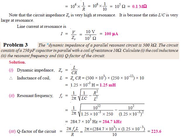
13 4.7 Tuned Amplifiers 70

14 71 EC T35/CIRCUIT THEORY

15 72 EC T35/CIRCUIT THEORY

16 73 EC T35/CIRCUIT THEORY
17 74 EC T35/CIRCUIT THEORY

18 75 EC T35/CIRCUIT THEORY

19 76 EC T35/CIRCUIT THEORY

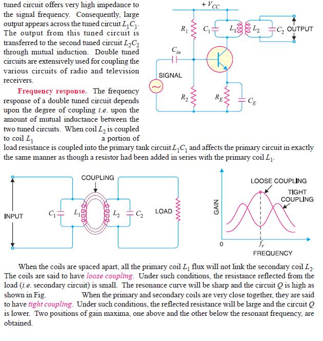
20 4.8 Double Tuned Amplifier 77
21 78 EC T35/CIRCUIT THEORY
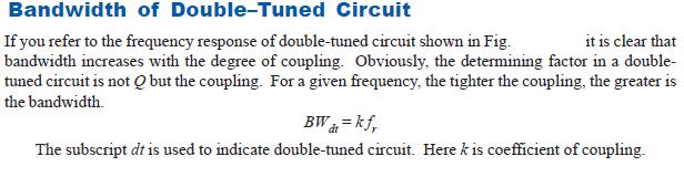
22 79 EC T35/CIRCUIT THEORY
Electromagnetic Induction
 Chapter 16 Electromagnetic Induction In This Chapter: Electromagnetic Induction Faraday s Law Lenz s Law The Transformer Self-Inductance Inductors in Combination Energy of a Current-Carrying Inductor Electromagnetic
EE 221 Circuits II. Chapter 13 Magnetically Coupled Circuits
 EE Circuits II Chapter 3 Magnetically Coupled Circuits Magnetically Coupled Circuits 3. What is a transformer? 3. Mutual Inductance 3.3 Energy in a Coupled Circuit 3.4 inear Transformers 3.5 Ideal Transformers
PHYS 1442 Section 004 Lecture #15
 PHYS 1442 Section 004 Lecture #15 Monday March 17, 2014 Dr. Andrew Brandt Chapter 21 Generator Transformer Inductance 3/17/2014 1 PHYS 1442-004, Dr. Andrew Brandt Announcements HW8 on Ch 21-22 will be
PESIT Bangalore South Campus Hosur road, 1km before Electronic City, Bengaluru -100 Department of Electronics & Communication Engineering
 CONTINUOUS INTERNAL EVALUATION TEST -1 Date : 27/2/2018 Marks:60 Subject & Code : Basic Electrical Engineering, 17ELE25 Section: A,B,C,D,E Time : 8:30 am 11:30 a.m Name of faculty: Mrs. Dhanashree Bhate,
Review: Lecture 9. Instantaneous and Average Power. Effective or RMS Value. Apparent Power and Power Factor. Complex Power. Conservation of AC Power
 Review: Lecture 9 Instantaneous and Average Power p( t) VmI m cos ( v i ) VmI m cos ( t v i ) Maximum Average Power Transfer Z L R L jx Effective or RMS Value I rms I m L R P * TH Apparent Power and Power
13. Magnetically Coupled Circuits
 13. Magnetically Coupled Circuits The change in the current flowing through an inductor induces (creates) a voltage in the conductor itself (self-inductance) and in any nearby conductors (mutual inductance)
An induced emf is the negative of a changing magnetic field. Similarly, a self-induced emf would be found by
 This is a study guide for Exam 4. You are expected to understand and be able to answer mathematical questions on the following topics. Chapter 32 Self-Induction and Induction While a battery creates an
PHYS 1441 Section 001 Lecture #22 Wednesday, Nov. 29, 2017
 PHYS 1441 Section 001 Lecture #22 Chapter 29:EM Induction & Faraday s Law Transformer Electric Field Due to Changing Magnetic Flux Chapter 30: Inductance Mutual and Self Inductance Energy Stored in Magnetic
PHYS 1444 Section 501 Lecture #20
 PHYS 1444 Section 501 Lecture #0 Monday, Apr. 17, 006 Transformer Generalized Faraday s Law Inductance Mutual Inductance Self Inductance Inductor Energy Stored in the Magnetic Field 1 Announcements Quiz
10 Electromagnetic Interactions
 Lab 10 Electromagnetic Interactions What You Need To Know: The Physics Electricity and magnetism are intrinsically linked and not separate phenomena. A changing magnetic field can create an electric field
Electric Circuits II Magnetically Coupled Circuits. Dr. Firas Obeidat
 Electric Circuits II Magnetically Coupled Circuits Dr. Firas Obeidat 1 Table of contents 1 Mutual Inductance 2 Dot Convention 3 Analyze Circuits Involving Mutual Inductance 4 Energy in a Coupled Circuit
Chapter 16: Mutual Inductance
 Chapter 16: Mutual Inductance Instructor: Jean-François MILLITHALER http://faculty.uml.edu/jeanfrancois_millithaler/funelec/spring2017 Slide 1 Mutual Inductance When two coils are placed close to each
EE2003 Circuit Theory Chapter 13 Magnetically Coupled Circuits
 EE003 Circuit Theory Chapter 3 Magnetically Coupled Circuits Copyright The McGraw-Hill Companies, Inc. Permission required for reproduction or display. Magnetically Coupled Circuit Chapter 3 3. What is
The SI unit of inductance is the henry, defined as:
 Inductors A coil of wire, or solenoid, can be used in a circuit to store energy in the magnetic field. We define the inductance of a solenoid having N turns, length l and cross-section area A as: The SI
#8A RLC Circuits: Free Oscillations
 #8A RL ircuits: Free Oscillations Goals In this lab we investigate the properties of a series RL circuit. Such circuits are interesting, not only for there widespread application in electrical devices,
Exclusive Technology Feature. Leakage Inductance (Part 1): Friend Or Foe? The Underlying Physics. ISSUE: October 2015
: Friend Or Foe? The Underlying Physics. ISSUE: October 2015") ISSUE: October 2015 Leakage Inductance (Part 1): Friend Or Foe? by Ernie Wittenbreder, Technical Witts, Flagstaff, Ariz There are situations in which leakage inductance in a transformer or coupled inductor
ISSUE: October 2015 Leakage Inductance (Part 1): Friend Or Foe? by Ernie Wittenbreder, Technical Witts, Flagstaff, Ariz There are situations in which leakage inductance in a transformer or coupled inductor
Chapter 13 Magnetically Coupled Circuits. Chapter Objectives:
 Chapter 13 Magnetically Coupled Circuits Chapter Objectives: Understand magnetically coupled circuits. Learn the concept of mutual inductance. Be able to determine energy in a coupled circuit. Learn how
EE 42/100 Lecture 16: Inductance. Rev B 3/15/2010 (8:55 PM) Prof. Ali M. Niknejad
 Prof. Ali M. Niknejad") A. M. Niknejad University of California, Berkeley EE 100 / 42 Lecture 16 p. 1/23 EE 42/100 Lecture 16: Inductance ELECTRONICS Rev B 3/15/2010 (8:55 PM) Prof. Ali M. Niknejad University of California, Berkeley
A. M. Niknejad University of California, Berkeley EE 100 / 42 Lecture 16 p. 1/23 EE 42/100 Lecture 16: Inductance ELECTRONICS Rev B 3/15/2010 (8:55 PM) Prof. Ali M. Niknejad University of California, Berkeley
Introduction. Inductors in AC Circuits.
 Module 3 AC Theory What you ll learn in Module 3. Section 3.1 Electromagnetic Induction. Magnetic Fields around Conductors. The Solenoid. Section 3.2 Inductance & Back e.m.f. The Unit of Inductance. Factors
Transformers. Dr. Gamal Sowilam
 Transformers Dr. Gamal Sowilam OBJECTIVES Become familiar with the flux linkages that exist between the coils of a transformer and how the voltages across the primary and secondary are established. Understand
ET1210: Module 5 Inductance and Resonance
 Part 1 Inductors Theory: When current flows through a coil of wire, a magnetic field is created around the wire. This electromagnetic field accompanies any moving electric charge and is proportional to
Unit-4. Magnetic Circuits
 Unit-4 Magnetic Circuits Topics to be Discussed Magnetic Coupling. Coefficient of Coupling (k). Sign of Mutual Voltage. Dot Convention. September 9, 0 Magnetic Circuits Magnetically Coupled Circuits A
Basic Analog Circuits
 Basic Analog Circuits Overview This tutorial is part of the National Instruments Measurement Fundamentals series. Each tutorial in this series, will teach you a specific topic of common measurement applications,
Flyback Converter for High Voltage Capacitor Charging
 Flyback Converter for High Voltage Capacitor Charging Tony Alfrey (tonyalfrey at earthlink dot net) A Flyback Converter is a type of switching power supply that may be used to generate an output voltage
Exam 3 Review Session
 Exam 3 Review Session I will hold a review for Exam 3 which covers Chapters 27, 28, 29 and 30, on Wednesday November 7 th at 7:15pm in MPHY 205. Exam 3 will be given in class on Thursday, November 8 th.
INDUCTOR. Inductors are electronic components that oppose a change in current. Air Core Inductor Symbol
 BASIC ELECTRICAL INDUCTOR INTRODUCTION are used for their ability to lter high frequencies out of the audio in a sound system. As an introduction to the focus of this lesson will be to discuss the different
total j = BA, [1] = j [2] total
![total j = BA, [1] = j [2] total](/thumbs/85/91692343.jpg "total j = BA, [1] = j [2] total") Name: S.N.: Experiment 2 INDUCTANCE AND LR CIRCUITS SECTION: PARTNER: DATE: Objectives Estimate the inductance of the solenoid used for this experiment from the formula for a very long, thin, tightly wound
Name: S.N.: Experiment 2 INDUCTANCE AND LR CIRCUITS SECTION: PARTNER: DATE: Objectives Estimate the inductance of the solenoid used for this experiment from the formula for a very long, thin, tightly wound
ELECTROMAGNETIC INDUCTION AND ALTERNATING CURRENT (Assignment)
") ELECTROMAGNETIC INDUCTION AND ALTERNATING CURRENT (Assignment) 1. In an A.C. circuit A ; the current leads the voltage by 30 0 and in circuit B, the current lags behind the voltage by 30 0. What is the
ELECTROMAGNETIC INDUCTION AND ALTERNATING CURRENT (Assignment) 1. In an A.C. circuit A ; the current leads the voltage by 30 0 and in circuit B, the current lags behind the voltage by 30 0. What is the
Inductance in DC Circuits
 Inductance in DC Circuits Anurag Srivastava Concept: Inductance is characterized by the behavior of a coil of wire in resisting any change of electric current through the coil. Arising from Faraday's law,
Alternating Current. Slide 1 / 69. Slide 2 / 69. Slide 3 / 69. Topics to be covered. Sources of Alternating EMF. Sources of alternating EMF
 Slide 1 / 69 lternating urrent Sources of alternating EMF Transformers ircuits and Impedance Topics to be covered Slide 2 / 69 LR Series ircuits Resonance in ircuit Oscillations Sources of lternating EMF
PART B. t (sec) Figure 1
 Figure 1") Code No: R16128 R16 SET 1 I B. Tech II Semester Regular Examinations, April/May 217 ELECTRICAL CIRCUIT ANALYSIS I (Electrical and Electronics Engineering) Time: 3 hours Max. Marks: 7 Note: 1. Question
Code No: R16128 R16 SET 1 I B. Tech II Semester Regular Examinations, April/May 217 ELECTRICAL CIRCUIT ANALYSIS I (Electrical and Electronics Engineering) Time: 3 hours Max. Marks: 7 Note: 1. Question
Alternating Current. Slide 2 / 69. Slide 1 / 69. Slide 3 / 69. Slide 4 / 69. Slide 6 / 69. Slide 5 / 69. Topics to be covered
 Slide 1 / 69 lternating urrent Sources of alternating EMF ircuits and Impedance Slide 2 / 69 Topics to be covered LR Series ircuits Resonance in ircuit Oscillations Slide 3 / 69 Sources of lternating EMF
Lab 7 - Inductors and LR Circuits
 Lab 7 Inductors and LR Circuits L7-1 Name Date Partners Lab 7 - Inductors and LR Circuits The power which electricity of tension possesses of causing an opposite electrical state in its vicinity has been
13 th Asian Physics Olympiad India Experimental Competition Wednesday, 2 nd May 2012
 13 th Asian Physics Olympiad India Experimental Competition Wednesday, nd May 01 Please first read the following instructions carefully: 1. The time available is ½ hours for each of the two experimental
AP Physics C. Alternating Current. Chapter Problems. Sources of Alternating EMF
 AP Physics C Alternating Current Chapter Problems Sources of Alternating EMF 1. A 10 cm diameter loop of wire is oriented perpendicular to a 2.5 T magnetic field. What is the magnetic flux through the
PHYSICS WORKSHEET CLASS : XII. Topic: Alternating current
 PHYSICS WORKSHEET CLASS : XII Topic: Alternating current 1. What is mean by root mean square value of alternating current? 2. Distinguish between the terms effective value and peak value of an alternating
Chapter Moving Charges and Magnetism
 100 Chapter Moving Charges and Magnetism 1. The power factor of an AC circuit having resistance (R) and inductance (L) connected in series and an angular velocity ω is [2013] 2. [2002] zero RvB vbl/r vbl
Chapter 11. Alternating Current
 Unit-2 ECE131 BEEE Chapter 11 Alternating Current Objectives After completing this chapter, you will be able to: Describe how an AC voltage is produced with an AC generator (alternator) Define alternation,
ECE 241L Fundamentals of Electrical Engineering. Experiment 8 A-C Transformer, Magnetization & Hysteresis
 ECE 241L Fundamentals of Electrical Engineering Experiment 8 A-C Transformer, Magnetization & Hysteresis A. Objectives: I. Measure leakage inductance and resistance loss II. Measure magnetization inductance
Lab 6 - Inductors and LR Circuits
 Lab 6 Inductors and LR Circuits L6-1 Name Date Partners Lab 6 - Inductors and LR Circuits The power which electricity of tension possesses of causing an opposite electrical state in its vicinity has been
Electromagnetic Induction - A
 Electromagnetic Induction - A APPARATUS 1. Two 225-turn coils 2. Table Galvanometer 3. Rheostat 4. Iron and aluminum rods 5. Large circular loop mounted on board 6. AC ammeter 7. Variac 8. Search coil
Power Electronics. Prof. B. G. Fernandes. Department of Electrical Engineering. Indian Institute of Technology, Bombay.
 Power Electronics Prof. B. G. Fernandes Department of Electrical Engineering Indian Institute of Technology, Bombay Lecture - 28 So far we have studied 4 different DC to DC converters. They are; first
Physics for Scientists & Engineers 2 2 = 1 LC. Review ( ) Review (2) Review (3) e! Rt. cos "t + # ( ) q = q max. Spring Semester 2005 Lecture 30 U E
 Review (2) Review (3) e! Rt. cos t + # ( ) q = q max. Spring Semester 2005 Lecture 30 U E") Review hysics for Scientists & Engineers Spring Semester 005 Lecture 30! If we have a single loop RLC circuit, the charge in the circuit as a function of time is given by! Where q = q max e! Rt L cos "t
Review hysics for Scientists & Engineers Spring Semester 005 Lecture 30! If we have a single loop RLC circuit, the charge in the circuit as a function of time is given by! Where q = q max e! Rt L cos "t
Faraday Laws of Electromagnetic Induction CLIL LESSON
 Faraday Laws of Electromagnetic Induction CLIL LESSON Experimental trials Michael Faraday-1931 This law shows the relationship between electric circuit and magnetic field A coil is connected to a galvanometer
Transformers. Objectives
 Transformers Objectives Explain mutual inductance Describe how a transformer is constructed and how it works Explain how a step-up transformer works Explain how a step-down transformer works Discuss the
ESO 210 Introduction to Electrical Engineering
 ESO 210 Introduction to Electrical Engineering Lecture-19 Magnetic Circuits and Introduction to Transformers 2 SERIES CONNECTION OF MUTUALLY COUPLED COILS A mutual term will alter the total inductance
SIDDHARTH GROUP OF INSTITUTIONS :: PUTTUR (AUTONOMOUS) Siddharth Nagar, Narayanavanam Road QUESTION BANK (DESCRIPTIVE) UNIT I INTRODUCTION
 Siddharth Nagar, Narayanavanam Road QUESTION BANK (DESCRIPTIVE) UNIT I INTRODUCTION") SIDDHARTH GROUP OF INSTITUTIONS :: PUTTUR (AUTONOMOUS) Siddharth Nagar, Narayanavanam Road 517583 QUESTION BANK (DESCRIPTIVE) Subject with Code : Electrical Circuits(16EE201) Year & Sem: I-B.Tech & II-Sem
SIDDHARTH GROUP OF INSTITUTIONS :: PUTTUR (AUTONOMOUS) Siddharth Nagar, Narayanavanam Road 517583 QUESTION BANK (DESCRIPTIVE) Subject with Code : Electrical Circuits(16EE201) Year & Sem: I-B.Tech & II-Sem
Chapter 24. Alternating Current Circuits
 Chapter 24 Alternating Current Circuits Objective of Lecture Generators and Motors Inductance RL Circuits (resistance and inductance) Transformers AC REMINDER: WORK ON THE EXAMPLES Read physics in perspective
Alternating Current Study Guide. Preface. This module is DIFFICULT.
 Preface This module is DIFFICULT. This material will take more effort to understand and more effort to pass than tests from previous modules. This is on par with a college-level electrical engineering
Name: Lab Partner: Section: The purpose of this lab is to study induction. Faraday s law of induction and Lenz s law will be explored. B = B A (8.
 Chapter 8 Induction - Faraday s Law Name: Lab Partner: Section: 8.1 Purpose The purpose of this lab is to study induction. Faraday s law of induction and Lenz s law will be explored. 8.2 Introduction It
Chapter 7. Response of First-Order RL and RC Circuits
 Chapter 7. Response of First-Order RL and RC Circuits By: FARHAD FARADJI, Ph.D. Assistant Professor, Electrical Engineering, K.N. Toosi University of Technology http://wp.kntu.ac.ir/faradji/electriccircuits1.htm
Advanced electromagnetism and electromagnetic induction
 Advanced electromagnetism and electromagnetic induction This worksheet and all related files are licensed under the Creative Commons Attribution License, version 1.0. To view a copy of this license, visit
CHAPTER 9. Sinusoidal Steady-State Analysis
 CHAPTER 9 Sinusoidal Steady-State Analysis 9.1 The Sinusoidal Source A sinusoidal voltage source (independent or dependent) produces a voltage that varies sinusoidally with time. A sinusoidal current source
UNIT 1 CIRCUIT ANALYSIS 1 What is a graph of a network? When all the elements in a network is replaced by lines with circles or dots at both ends.
 UNIT 1 CIRCUIT ANALYSIS 1 What is a graph of a network? When all the elements in a network is replaced by lines with circles or dots at both ends. 2 What is tree of a network? It is an interconnected open
Electromagnetic Oscillations and Currents. March 23, 2014 Chapter 30 1
 Electromagnetic Oscillations and Currents March 23, 2014 Chapter 30 1 Driven LC Circuit! The voltage V can be thought of as the projection of the vertical axis of the phasor V m representing the time-varying
V.S.B ENGINEERING COLLEGE DEPARTMENT OF ELECTRICAL AND ELECTRONICS ENGINEERING I EEE-II Semester all subjects 2 & 16 marks QB
 V.S.B ENGINEERING COLLEGE DEPARTMENT OF ELECTRICAL AND ELECTRONICS ENGINEERING I EEE-II Semester all subjects 2 & 16 marks QB Sl.No Subject Name Page No. 1 Circuit Theory 2 1 UNIT-I CIRCUIT THEORY TWO
1. If the flux associated with a coil varies at the rate of 1 weber/min,the induced emf is
 1. f the flux associated with a coil varies at the rate of 1 weber/min,the induced emf is 1 1. 1V 2. V 60 3. 60V 4. Zero 2. Lenz s law is the consequence of the law of conservation of 1. Charge 2. Mass
Bakiss Hiyana binti Abu Bakar JKE, POLISAS BHAB
 1 Bakiss Hiyana binti Abu Bakar JKE, POLISAS 1. Explain AC circuit concept and their analysis using AC circuit law. 2. Apply the knowledge of AC circuit in solving problem related to AC electrical circuit.
Look over Chapter 31 sections 1-4, 6, 8, 9, 10, 11 Examples 1-8. Look over Chapter 21 sections Examples PHYS 2212 PHYS 1112
 PHYS 2212 Look over Chapter 31 sections 1-4, 6, 8, 9, 10, 11 Examples 1-8 PHYS 1112 Look over Chapter 21 sections 11-14 Examples 16-18 Good Things To Know 1) How AC generators work. 2) How to find the
A.C. Circuits -- Conceptual Solutions
 A.C. Circuits -- Conceptual Solutions 1.) Charge carriers in a DC circuit move in one direction only. What do charge carriers do in an AC circuit? Solution: The voltage difference between the terminals
Unit-1(A) Circuit Analysis Techniques
 Circuit Analysis Techniques") Unit-1(A Circuit Analysis Techniques Basic Terms used in a Circuit 1. Node :- It is a point in a circuit where two or more circuit elements are connected together. 2. Branch :- It is that part of a network
Unit-1(A Circuit Analysis Techniques Basic Terms used in a Circuit 1. Node :- It is a point in a circuit where two or more circuit elements are connected together. 2. Branch :- It is that part of a network
TRANSFORMER THEORY. Mutual Induction
 Transformers Transformers are used extensively for AC power transmissions and for various control and indication circuits. Knowledge of the basic theory of how these components operate is necessary to
PHYS 1444 Section 003 Lecture #19
 PHYS 1444 Section 003 Lecture #19 Monday, Nov. 14, 2005 Electric Generators DC Generator Eddy Currents Transformer Mutual Inductance Today s homework is homework #10, due noon, next Tuesday!! 1 Announcements
11. AC-resistances of capacitor and inductors: Reactances.
 11. AC-resistances of capacitor and inductors: Reactances. Purpose: To study the behavior of the AC voltage signals across elements in a simple series connection of a resistor with an inductor and with
15. the power factor of an a.c circuit is.5 what will be the phase difference between voltage and current in this
 1 1. In a series LCR circuit the voltage across inductor, a capacitor and a resistor are 30 V, 30 V and 60 V respectively. What is the phase difference between applied voltage and current in the circuit?
CHAPTER 7. Response of First-Order RL and RC Circuits
 CHAPTER 7 Response of First-Order RL and RC Circuits RL and RC Circuits RL (resistor inductor) and RC (resistor-capacitor) circuits. Figure 7.1 The two forms of the circuits for natural response. (a) RL
REQUIRED SKILLS AND KNOWLEDGE UEENEEG101A. Electromagnetic devices and circuits. Topic and Description NIDA Lesson CARD # Magnetism encompassing:
 REQUIRED SKILLS AND KNOWLEDGE UEENEEG101A KS01-EG101A Electromagnetic devices and circuits T1 Magnetism encompassing: Topic and Description NIDA Lesson CARD # magnetic field pattern of bar and horse-shoe
Chapt ha e pt r e r 11 Inductors
 Chapter 11 Inductors The Basic Inductor When a length of wire is formed onto a coil, it becomes a basic inductor Magnetic lines of force around each loop in the winding of the coil effectively add to the
PROBLEMS. Figure13.74 For Prob Figure13.72 For Prob Figure13.75 For Prob Figure13.73 For Prob Figure13.76 For Prob
 CHAPTER 13 Magnetically Coupled Circuits 571 13.9 In order to match a source with internal impedance of 500 to a 15- load, what is needed is: (a) step-up linear transformer (b) step-down linear transformer
Reg. No. : BASIC ELECTRICAL TECHNOLOGY (ELE 101)
") Department of Electrical and Electronics Engineering Reg. No. : MNIPL INSTITUTE OF TECHNOLOGY, MNIPL ( Constituent Institute of Manipal University, Manipal) FIRST SEMESTER B.E. DEGREE MKEUP EXMINTION (REVISED
Department of Electrical and Electronics Engineering Reg. No. : MNIPL INSTITUTE OF TECHNOLOGY, MNIPL ( Constituent Institute of Manipal University, Manipal) FIRST SEMESTER B.E. DEGREE MKEUP EXMINTION (REVISED
ELECTRICAL CIRCUITS LABORATORY MANUAL (II SEMESTER)
") ELECTRICAL CIRCUITS LABORATORY MANUAL (II SEMESTER) LIST OF EXPERIMENTS. Verification of Ohm s laws and Kirchhoff s laws. 2. Verification of Thevenin s and Norton s Theorem. 3. Verification of Superposition
ELECTRICAL CIRCUITS LABORATORY MANUAL (II SEMESTER) LIST OF EXPERIMENTS. Verification of Ohm s laws and Kirchhoff s laws. 2. Verification of Thevenin s and Norton s Theorem. 3. Verification of Superposition
Electrical Theory 2 Lessons for Fall Semester:
 Electrical Theory 2 Lessons for Fall Semester: Lesson 1 Magnetism Lesson 2 Introduction to AC Theory Lesson 3 Lesson 4 Capacitance and Capacitive Reactance Lesson 5 Impedance and AC Circuits Lesson 6 AC
Experiment 7: Undriven & Driven RLC Circuits
 MASSACHUSETTS INSTITUTE OF TECHNOLOGY Department of Physics 8.02 Spring 2006 OBJECTIVES Experiment 7: Undriven & Driven RLC Circuits 1. To explore the time dependent behavior of RLC Circuits, both driven
Bucking Coils produce Energy Gain Cyril Smith, 2015
 Bucking Coils produce Energy Gain Cyril Smith, 015 1. Introduction There are many claims of overunity for systems that employ bucking coils. These are coils mounted on a common core and connected in series
Electromagnetism - Grade 11
 OpenStax-CNX module: m32837 1 Electromagnetism - Grade 11 Rory Adams Free High School Science Texts Project Mark Horner Heather Williams This work is produced by OpenStax-CNX and licensed under the Creative
Physics 202 Midterm Exam 3 Nov 30th, 2011
 Physics 202 Midterm Exam 3 Nov 30th, 2011 Name: Student ID: Section: TA (please circle): Daniel Crow Scott Douglas Yutao Gong Taylor Klaus Aaron Levine Andrew Loveridge Jason Milhone Hojin Yoo Instructions:
In this lecture. Electromagnetism. Electromagnetism. Oersted s Experiment. Electricity & magnetism are different aspects of the same basic phenomenon:
 In this lecture Electromagnetism Electromagnetic Effect Electromagnets Electromechanical Devices Transformers Electromagnetic Effect Electricity & magnetism are different aspects of the same basic phenomenon:
Electrical Fundamentals and Basic Components Chapters T2, T3, G4
 Electrical Fundamentals and Basic Components Chapters T2, T3, G4 Some Basic Math, Electrical Fundamentals, AC Power, The Basics of Basic Components, A Little More Component Detail, Reactance and Impedance
Practice problems for the 3 rd midterm (Fall 2010)
") Practice problems for the 3 rd midterm (Fall 2010) 1. A video camera is set in an unknown liquid. When you change the angle to look up the liquid-air boundary, at certain point, it looks like mirror on
Practice problems for the 3 rd midterm (Fall 2010) 1. A video camera is set in an unknown liquid. When you change the angle to look up the liquid-air boundary, at certain point, it looks like mirror on
Electrical Engineering / Electromagnetics
 Electrical Engineering / Electromagnetics. Plot voltage versus time and current versus time for the circuit with the following substitutions: A. esistor B. Capacitor C. Inductor t = 0 A/B/C A. I t t B.
Inductors & Resonance
 Inductors & Resonance The Inductor This figure shows a conductor carrying a current. A magnetic field is set up around the conductor as concentric circles. If a coil of wire has a current flowing through
General Licensing Class Circuits
 General Licensing Class Circuits Valid July 1, 2011 Through June 30, 2015 1 Amateur Radio General Class Element 3 Course Presentation ELEMENT 3 SUB-ELEMENTS (Groupings) Your Passing CSCE Your New General
ELECTROMAGNETIC COMPATIBILITY HANDBOOK 1. Chapter 8: Cable Modeling
 ELECTROMAGNETIC COMPATIBILITY HANDBOOK 1 Chapter 8: Cable Modeling Related to the topic in section 8.14, sometimes when an RF transmitter is connected to an unbalanced antenna fed against earth ground
Chapter 28 Alternating Current Circuits
 History teaches us that the searching spirit of man required thousands of years for the discovery of the fundamental principles of the sciences, on which the superstructure was then raised in a comparatively
PH213 Chapter 26 solutions
 PH213 Chapter 26 solutions 26.6. IDENTIFY: The potential drop is the same across the resistors in parallel, and the current into the parallel combination is the same as the current through the 45.0-Ω resistor.
Chapter 33. Alternating Current Circuits
 Chapter 33 Alternating Current Circuits Alternating Current Circuits Electrical appliances in the house use alternating current (AC) circuits. If an AC source applies an alternating voltage to a series
TRANSFORMERS INTRODUCTION
 Tyco Electronics Corporation Crompton Instruments 1610 Cobb International Parkway, Unit #4 Kennesaw, GA 30152 Tel. 770-425-8903 Fax. 770-423-7194 TRANSFORMERS INTRODUCTION A transformer is a device that
Chapter 33. Alternating Current Circuits
 Chapter 33 Alternating Current Circuits C HAP T E O UTLI N E 33 1 AC Sources 33 2 esistors in an AC Circuit 33 3 Inductors in an AC Circuit 33 4 Capacitors in an AC Circuit 33 5 The L Series Circuit 33
LM78S40 Switching Voltage Regulator Applications
 LM78S40 Switching Voltage Regulator Applications Contents Introduction Principle of Operation Architecture Analysis Design Inductor Design Transistor and Diode Selection Capacitor Selection EMI Design
Review 6. unlike poles cause the magnets to attract. like poles cause the magnets to repel.
 Review 6 1. The two characteristics of all magnets are: they attract and hold Iron, and, if free to move, they will assume roughly a south - north position. 2. Lines of flux always leave the north pole
VALLIAMMAI ENGINEERING COLLEGE
 P a g e 2 Question Bank Programme Subject Semester / Branch : BE : EE6201-CIRCUIT THEORY : II/EEE,ECE &EIE UNIT-I PART-A 1. Define Ohm s Law (B.L.T- 1) 2. List and define Kirchoff s Laws for electric circuits.
Experiment VI: The LRC Circuit and Resonance
 Experiment VI: The ircuit and esonance I. eferences Halliday, esnick and Krane, Physics, Vol., 4th Ed., hapters 38,39 Purcell, Electricity and Magnetism, hapter 7,8 II. Equipment Digital Oscilloscope Digital
Inductance. Chapter 30. PowerPoint Lectures for University Physics, Thirteenth Edition Hugh D. Young and Roger A. Freedman. Lectures by Wayne Anderson
 Chapter 30 Inductance PowerPoint Lectures for University Physics, Thirteenth Edition Hugh D. Young and Roger A. Freedman Lectures by Wayne Anderson Goals for Chapter 30 To learn how current in one coil
Experiment 9: AC circuits
 Experiment 9: AC circuits Nate Saffold nas2173@columbia.edu Office Hour: Mondays, 5:30PM-6:30PM @ Pupin 1216 INTRO TO EXPERIMENTAL PHYS-LAB 1493/1494/2699 Introduction Last week (RC circuit): This week:
Impedance, Resonance, and Filters. Al Penney VO1NO
 Impedance, Resonance, and Filters A Quick Review Before discussing Impedance, we must first understand capacitive and inductive reactance. Reactance Reactance is the opposition to the flow of Alternating
APPLICATION NOTE - 018
 APPLICATION NOTE - 018 Power Transformers Background Power Transformers are used within an AC power distribution systems to increase or decrease the operating voltage to achieve the optimum transmission
Downloaded from / 1
 PURWANCHAL UNIVERSITY II SEMESTER FINAL EXAMINATION-2008 LEVEL : B. E. (Computer/Electronics & Comm.) SUBJECT: BEG123EL, Electrical Engineering-I Full Marks: 80 TIME: 03:00 hrs Pass marks: 32 Candidates
Ac fundamentals and AC CIRCUITS. Q1. Explain and derive an expression for generation of AC quantity.
 Ac fundamentals and AC CIRCUITS Q1. Explain and derive an expression for generation of AC quantity. According to Faradays law of electromagnetic induction when a conductor is moving within a magnetic field,
Physics 227: Lecture 11 Circuits, KVL, KCL, Meters
 Physics 227: Lecture 11 Circuits, KVL, KCL, Meters Lecture 10 review: EMF ξ is not a voltage V, but OK for now. Physical emf source has V ab = ξ - Ir internal. Power in a circuit element is P = IV. For
Inductance, capacitance and resistance
 Inductance, capacitance and resistance As previously discussed inductors and capacitors create loads on a circuit. This is called reactance. It varies depending on current and frequency. At no frequency,