Alternating Current Study Guide. Preface. This module is DIFFICULT.
|
|
|
- Jonas Clark
- 6 years ago
- Views:
Transcription


1 Preface This module is DIFFICULT. This material will take more effort to understand and more effort to pass than tests from previous modules. This is on par with a college-level electrical engineering course. Let s break the module up into more manageable pieces, prioritize, and eat this elephant
2 Preface Sine Wave Generation Transformers Sine Wave Terminology and Characteristics Power in AC Circuits - Power Triangle - Power Factor Three Basic Circuit Load types: - Resistance - Inductance - capacitance Combination Load Circuits 35/2 ELI the ICE man
3 See pages 1 and 2 in the mod text. Alternating Current Study Guide Sine Wave Generation Two principles form the basis of all electromagnetic phenomena: - An electric current in a conductor creates a magnetic field that surrounds the conductor. - Relative motion between a conductor and a magnetic field when at least one component of that relative motion is in a direction that is perpendicular to the direction of the field, creates a voltage in a conductor.
4 See pages 1 and 2 in the mod text. Alternating Current Study Guide Sine Wave Generation Three factors affect the amount of voltage generated: 1. Strength of magnetic field (typically constant) 2. Length of wire loop (typically constant) 3. Phase angle (always changing) Here is the formula to find the magnitude of voltage at ANY phase angle: E = Emax sin Θ but what is a phase angle.
5 See pages 1 and 2 in the mod text. Alternating Current Study Guide Sine Wave Generation Here is the formula to find the magnitude of voltage at ANY phase angle: E = Emax sin Θ but what is a phase angle.
6 See pages 1 and 2 in the mod text. Alternating Current Study Guide Sine Wave Generation Here is the formula to find the magnitude of voltage at ANY phase angle: E = Emax sin Θ Learn how to use Google for calcs: sin 0 degrees sin 30 degrees sin 45 degrees sin 60 degrees sin 90 degrees
7 See pages 1 and 2 in the mod text. Alternating Current Study Guide Sine Wave Generation Here is the formula to find the magnitude of voltage at ANY phase angle: E = Emax sin Θ So if all the values of sine are fractional except for: sin 90 degrees = 1 sin 270 degrees = - 1 Therefore, the maximum value for voltage will occur at phase angles of?
8 See pages 3 thru 6 in the mod text. Alternating Current Study Guide Sine Wave Terminology and Characteristics Phase Angle (degrees) Frequency (Hz or cps) Amplitude (Volts and Amps) Time (secs) Cycle Period (secs) Alternation Peak (Volts and Amps) RMS (Volts) Average (Volts) Phase: in phase or out of phase
9 Magnitude of volts or amps See pages 3 thru 6 in the mod text. Alternating Current Study Guide Sine Wave Terminology and Characteristics Y Phase Angle or Time X
10 See pages 3 thru 6 in the mod text. Alternating Current Study Guide Sine Wave Terminology and Characteristics Cycle Alternation Each time a waveform changes from zero to peak and back to zero is called an? Two form a.
11 Sine Wave Terminology and Characteristics Frequency (Hz or cps) The frequency of a waveform is the number of times per second an identical pattern repeats itself or The number of cycles per second is the frequency What is the frequency of this wave form? In Hz? In cps? 1 sec frequency = cycles See pages 3 thru 6 in the mod text. secs
12 Sine Wave Terminology and Characteristics Frequency (Hz or cps) The frequency of a waveform is the number of times per second an identical pattern repeats itself. What is the frequency of this wave form? In Hz? In cps? 4 sec See pages 3 thru 6 in the mod text.
13 Sine Wave Terminology and Characteristics Frequency (Hz or cps) The frequency of a waveform is the number of times per second an identical pattern repeats itself. What is the frequency of this wave form? In Hz? In cps? 0.5 sec See pages 3 thru 6 in the mod text.
14 See pages 3 thru 6 in the mod text. Alternating Current Study Guide Sine Wave Terminology and Characteristics Period The period of a waveform is the time to complete one cycle t = time = period t = 1 cps
15 See pages 3 thru 6 in the mod text. Alternating Current Study Guide Sine Wave Terminology and Characteristics Period The period of a waveform is the time to complete one cycle t = 1 cps
16 See pages 3 thru 6 in the mod text. Alternating Current Study Guide Sine Wave Terminology and Characteristics Period The period of a waveform is the time to complete one cycle t = 1 cps 1.0
17 See pages 3 thru 6 in the mod text. Alternating Current Study Guide Sine Wave Terminology and Characteristics Period The period of a waveform is the time to complete one cycle t = 1 cps What is the period? 1 sec
18 See pages 3 thru 6 in the mod text. Alternating Current Study Guide Sine Wave Terminology and Characteristics Wavelength The wavelength lamba (Λ) is the distance traveled by a waveform during a period. Wavelength? Λ = tc t = 1/60 sec (for AC in United States or sec c = speed of electromagnetic radiation or 3 x 10 8 m/s or? sec 186,000 miles/sec or 9.8 x 10 8 ft/sec
19 See pages 3 thru 6 in the mod text. Alternating Current Study Guide Sine Wave Terminology and Characteristics Wavelength The wavelength lamba (Λ) is the distance traveled by a waveform during a period. Wavelength? Λ = tc Wavelength: 300,000,000/60 = 5,000,000 m 980,000,000/60 = 16,333,000 ft t = 1/60 sec (for AC in United States or sec c = speed of electromagnetic radiation or 3 x 10 8 m/s or? sec 186,000 miles/sec or 9.8 x 10 8 ft/sec Two wavelengths: 1/30 sec or secs
20 Sine Wave Terminology and Characteristics Peak RMS Average
21 Sine Wave Terminology and Characteristics Peak RMS Average Average = x Peak Peak = Average / RMS = x Peak Peak = RMS / KNOW THESE FORMULAS!!
22 Sine Wave Terminology and Characteristics Peak RMS Average If Peak-to-Peak is 700V, What is Peak?
23 Sine Wave Terminology and Characteristics Peak RMS Average If Peak-to-Peak is 700V, What is Peak? 350V If Peak is 350V, what is RMS? Average?
24 Sine Wave Terminology and Characteristics Peak RMS Average If Peak-to-Peak is 700V, What is Peak? 350V If Peak is 350V, what is RMS? 247V Average? 223V
25 Sine Wave Terminology and Characteristics Peak RMS Average If Peak-to-Peak is 340V, What is Peak? What is RMS? What is Avg?
26 Sine Wave Terminology and Characteristics Peak RMS Average If Peak-to-Peak is 340V, What is Peak? 170V If Peak is 170V what is RMS? 120V Average? 108V
27 Sine Wave Terminology and Characteristics Peak RMS Average If Peak is 392V What is RMS? What is Avg?
28 Sine Wave Terminology and Characteristics Peak RMS Average If Peak is 392V What is RMS? 277V What is Avg? 250V
29 Sine Wave Terminology and Characteristics Peak RMS Average If RMS is 200V What is Peak? What is Avg?
30 Sine Wave Terminology and Characteristics Peak RMS Average If RMS is 200V What is Peak? 283V What is Avg? 180V
31 Sine Wave Terminology and Characteristics Peak RMS Average If AVG is 300V What is RMS? What is Peak?
32 Sine Wave Terminology and Characteristics Peak RMS Average If AVG is 300V What is RMS? 333V What is Peak? 471V
33 Sine Wave Terminology and Characteristics Peak RMS Average If Peak is 150V What Peak-to-Peak?
34 Sine Wave Terminology and Characteristics Peak RMS Average If Peak is 150V What Peak-to-Peak? 300V
35 Sine Wave Terminology and Characteristics Peak RMS Average If AVG is 125V What is RMS? What is Peak?
36 Sine Wave Terminology and Characteristics Peak RMS Average If AVG is 125V What is RMS? 139V What is Peak? 196V
37 Sine Wave Terminology and Characteristics Peak RMS Average If RMS is 125V What is Peak-to-Peak? What is avg? What is Peak?
38 Sine Wave Terminology and Characteristics Peak RMS Average If RMS is 125V What is Peak-to-Peak? 354V What is AVG? 113V What is Peak? 177V

39 Sine Wave Terminology and Characteristics RMS relates directly to an equivalent DC value:
40 Peak, RMS, DC (constant value) Sine Wave Terminology and Characteristics What is peak? What is peak to peak?


41 Peak, RMS, DC (constant value) Sine Wave Terminology and Characteristics What is peak? 339V What is peak to peak? 678V In the field, we ALMOST ALWAYS work with RMS values for AC circuits. Unless explicitly indicated otherwise, assume you are using RMS voltage values.
42 Sine Wave Terminology and Characteristics Phase: -In phase -Out of phase Waves are in phase when they cross the zero points (x-axis) at the same time and the peaks occur, with the same sign (positive or negative) at the same time.
43 Sine Wave Terminology and Characteristics Phase: -In phase -Out of phase Waves are in phase when they cross the zero points (x-axis) at the same time and the peaks occur, with the same sign (positive or negative) at the same time. In phase or out of phase?

 at the same time.")
44 Sine Wave Terminology and Characteristics Phase: -In phase -Out of phase Waves are in phase when they cross the zero points (x-axis) at the same time and the peaks occur, with the same sign (positive or negative) at the same time. In phase or out of phase?
45 Sine Wave Terminology and Characteristics Phase: -In phase -Out of phase Waves are in phase when they cross the zero points (x-axis) at the same time and the peaks occur, with the same sign (positive or negative) at the same time. In phase or out of phase?
 In phase or out of phase?")
46 Sine Wave Terminology and Characteristics Phase: -In phase -Out of phase If we think of a wave as having peaks and valleys with a zero-crossing between them, the phase of the wave is defined as the distance between the first zero-crossing and the point in space defined as the origin. - and have the same sign (i.e., positive ot negative) In phase or out of phase? How many degrees out of phase?
47 Sine Wave Terminology and Characteristics Phase: -In phase -Out of phase Waves are in phase when they cross the zero points (x-axis) at the same time and the peaks occur, with the same sign (positive or negative) at the same time. In phase or out of phase? How many degrees out of phase?
48 Sine Wave Terminology and Characteristics Phase: -In phase -Out of phase Waves are in phase when they cross the zero points (x-axis) at the same time and the peaks occur, with the same sign (positive or negative) at the same time. In phase or out of phase? How many degrees out of phase?
49 Sine Wave Terminology and Characteristics Don t forget, there are non-sinusoidal wave forms. Phase angle is only used for the sine wave because it is the only one which results from rotation generation.
50 Sine Wave Terminology and Characteristics Quiz 1 1. The minimum voltage is generated by rotating wire when the conductor is moving. a. Across the field at 90 degrees b. With the field at 0 degrees and 180 degrees c. Across the fields at 45 degrees d. Against the field at 180 degrees 2. For an AC circuit, one full cycle represents. a. 0 degrees b. 90 degrees c. 270 degrees d. 360 degrees 3. What is the Hz rating of an AC circuit if the frequency is 60 cycles per ½ second? 4. A circuit has a peak value of 310V, what is the average value?
51 Sine Wave Terminology and Characteristics Quiz 1 1. The minimum voltage is generated by rotating wire when the conductor is moving. a. Across the field at 90 degrees b. With the field at 0 degrees and 180 degrees c. Across the fields at 45 degrees d. Against the field at 180 degrees 2. For an AC circuit, one full cycle represents. a. 0 degrees b. 90 degrees c. 270 degrees d. 360 degrees 3. What is the Hz rating of an AC circuit if the frequency is 60 cycles per ½ second? 120Hz 4. A circuit has a peak value of 310V, what is the average value? 197.5V
52 Sine Wave Terminology and Characteristics Quiz 2 1. In sine wave terminology, the RMS value is a x peak b x peak c x peak d. 2 x peak 2. If the time for one cycle is 0.01 second, the frequency is a Hz b. 0.1 Hz c. 10 Hz d. 100 Hz 3. Normal AC electricity in North America changes directions how many times per second? 4. Each change of direction is question 3 is known as a(n) 5. Normal AC electricity in North America cycles how many times per second? 6. What is the frequency of normal AC electricity in North America?
53 Sine Wave Terminology and Characteristics Quiz 2 1. In sine wave terminology, the RMS value is a x peak b x peak c x peak d. 2 x peak 2. If the time for one cycle is 0.01 second, the frequency is a Hz b. 0.1 Hz c. 10 Hz d. 100 Hz 3. Normal AC electricity in North America changes directions how many times per second? 120 times or 120 alternations 4. Each change of direction in question 3 is known as a(n) alternation 5. Normal AC electricity in North America cycles how many times per second? 60 times per second or 60 Hz 6. What is the frequency of normal AC electricity in North America? 60 Hz
54 Sine Wave Terminology and Characteristics Quiz 3 1. The typical voltage values encountered in field work for a single phase AC circuit for receptacles is 120V. This values is a a. Peak value b. Peak-to-peak value c. Average value d. RMS value 2. If the phase angles for two sine waves are both 180 degrees, then the two waves. a. Have the same amplitude b. Are in phase c. Have the same peak values d. Are out of phase 3. Given a circuit has an RMS value of 277V, what is the peak value? 4. Given a circuit has an RMS value of 277V what is the peak-to-peak value? 5. Given a circuit has an RMS value of 277V what is the average value?
55 Sine Wave Terminology and Characteristics Quiz 3 1. The typical voltage values encountered in field work for a single phase AC circuit for receptacles is 120V. This values is a a. Peak value b. Peak-to-peak value c. Average value d. RMS value 2. If the phase angles for two sine waves are both 180 degrees, then the two waves. a. Have the same amplitude b. Are in phase c. Have the same peak values d. Are out of phase 3. Given a circuit has an RMS value of 277V, what is the peak value? 391V 4. Given a circuit has an RMS value of 277V what is the peak-to-peak value? 782V 5. Given a circuit has an RMS value of 277V what is the average value? 250V

 2.")
56 Basic Load Types Resistance, Inductance, Capacitance What types of loads do these groups of symbols represent? 1.) 2.) 3.)
57 Basic Load Type Resistance, Inductance, Capacitance AC source of voltage: Sine wave in a circle Resistive load symbol: Saw tooth wave.
58 Basic Load Type Resistance, Inductance, Capacitance AC source of voltage: Sine wave in a circle Resistive load symbol: Saw tooth wave. In purely* resistive AC circuits, Ohm s Law applies just as if this were DC circuit. (*purely resistive means no other load type in series or parallel in the circuit). E = IR
59 Basic Load Type Resistance, Inductance, Capacitance AC source of voltage: Sine wave in a circle Resistive load symbol: Saw tooth wave. 4 Ohms What is the current in this circuit? In purely* resistive AC circuits, Ohm s Law applies just as if this were DC circuit. (*purely resistive means no other load type in series or parallel in the circuit). E = IR
60 Basic Load Type Resistance, Inductance, Capacitance AC source of voltage: Sine wave in a circle 30 Amps Resistive load symbol: Saw tooth wave. 4 Ohms In purely* resistive AC circuits, Ohm s Law applies just as if this were DC circuit. (*purely resistive means no other load type in series or parallel in the circuit). E = IR
61 Basic Load Type Resistance, Inductance, Capacitance AC source of voltage: Sine wave in a circle To find I T, we need to find R T first 4 Ohms 6 Ohms To find R T, we have to use a parallel resistors formula. E = IR
62 Basic Load Type Resistance, Inductance, Capacitance (Reciprocal formula) R T = Ohms 6 Ohms R T = 4 x 6 (Product over sum) E = IR
63 Basic Load Type Resistance, Inductance, Capacitance (Reciprocal formula) R T = = 2.4 Ω 4 Ohms 6 Ohms R T = (Product over sum) 4 x = 2.4 Ω E = IR
64 Basic Load Type Resistance, Inductance, Capacitance (Reciprocal formula) R T = = 2.4 Ω 4 Ohms 6 Ohms R T = (Product over sum) 4 x = 2.4 Ω Now use Ohm s Law. E = IR
65 Basic Load Type Resistance, Inductance, Capacitance What are the units?? I T = E R 120 V = = 50 A 2.4 Ω 4 Ohms 6 Ohms E = IR
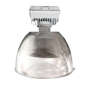
66 Basic Load Type Resistance, Inductance, Capacitance In purely* resistive AC circuits, Ohm s Law applies just as if this were DC circuit. (*purely resistive means no other load type in series or parallel in the circuit). What are examples of resistive loads?
. What are examples of resistive loads?")
67 Basic Load Type Resistance, Inductance, Capacitance In purely* resistive AC circuits, Ohm s Law applies just as if this were DC circuit. (*purely resistive means no other load type in series or parallel in the circuit). What are examples of resistive loads?
68 Basic Load Type Resistance, Inductance, Capacitance Capacitive load symbol:
69 Basic Load Type Resistance, Inductance, Capacitance Capacitor: A fundamental electrical element having two conducting surfaces separated by an insulating material and having the capacity to store charge on its plates. Capacitance: A measure of a capacitor s ability to store charge; measured in farads (F).
70 Basic Load Type Resistance, Inductance, Capacitance As the capacitor charges or discharges, a current flows through it which is restricted by the internal impedance of the capacitor. This internal impedance is commonly known as Capacitive Reactance and is given the symbol X C in Ohms. Unlike resistance which has a fixed value, for example, 100Ωs, 1kΩ, 10kΩ etc, (this is because resistance obeys Ohms Law), Capacitive Reactance varies with the applied frequency so any variation in supply frequency will have a big effect on the capacitors, capacitive reactance value. As the frequency applied to the capacitor increases, its effect is to decrease its reactance (measured in ohms). Likewise as the frequency across the capacitor decreases its reactance value increases. Notice frequency and capacitive resistance are INVERSELY related. Capacitance in farads 3.14 Frequency in HZ
71 Basic Load Type Resistance, Inductance, Capacitance Think of reactance as something that does the opposite of the main action it is a re-action and it resists the main action Hence reactance measured in ohms Capacitive Reactance Inductive Reactance Inductance measured In henrys. - Remember formulas with NFL and NFC. First make the jump that the symbol Π looks like a letter n. Now think of football the National Football Conference is a subset or subsidiary conference in the National Football League (put NFC in denominator) of the NFL.
72 Basic Load Type Resistance, Inductance, Capacitance Think of reactance as something that does the opposite of the main action it is a re-action and it resists the main action Hence reactance measured in ohms Capacitive Reactance Inductive Reactance Inductance measured In henrys. - Remember formulas with NFL and NFC. NFC is a subset (put NFC in denominator) of the NFL.
73 Basic Load Type Resistance, Inductance, Capacitance Factors that affect capacitance: Area of the plates: More area, more capacitance. Distance between plates: Less distance, more capacitance. Dielectric Permittivity: More permittivity, more capacitance.

74 Basic Load Type Resistance, Inductance, Capacitance Factors that affect capacitance: INVERSELY RELATED!!! Area of the plates: More area, more capacitance. Distance between plates: Less distance, more capacitance. Dielectric Permittivity: More permittivity, more capacitance.
75 Basic Load Type Resistance, Inductance, Capacitance When capacitors are in parallel this has the effect of making one capacitor with a larger area. This means capacitors in parallel can be added together to determine total capacitance. To determine overall capacitance in series, the reciprocal formula must be used. Putting capacitors in series has the effect of making the dielectric thicker. All of this means capacitors are calculated the opposite of resistors.!ay Caramba!
76 Basic Load Type Resistance, Inductance, Capacitance Given two capacitors are in series and one capacitor is 10 μf and another is 20 μf, what is C T? 10 μf 20 μf
77 Basic Load Type Resistance, Inductance, Capacitance Given two capacitors are in series and one capacitor is 10 μf and another is 20 μf, what is C T? 1 10 μf R T = μf Use reciprocal formula:
78 Basic Load Type Resistance, Inductance, Capacitance Given two capacitors are in series and one capacitor is 10 μf and another is 10 μf, what is C T? 1 10 μf R T = = 6.67 μf 10 μf Use reciprocal formula: Kirchoff s Law applies to voltage. E = V 1 + V 2 + V 3. Across each capacitor in series, the voltage will drop. In this case, this means each of the two equal capacitors has one-half the applied voltage.
79 Basic Load Type Resistance, Inductance, Capacitance Each of five equal capacitors in series has the applied voltage? a. 5% b. 5 times c. 50% d. 1/5
80 Basic Load Type Resistance, Inductance, Capacitance Each of five equal capacitors in series has the applied voltage? a. 5% b. 5 times c. 50% d. 1/5
81 Basic Load Type Resistance, Inductance, Capacitance Given two capacitors are in parallel and one capacitor is 10 μf and another is 20 μf, what is C T?
82 Basic Load Type Resistance, Inductance, Capacitance Given two capacitors are in parallel and one capacitor is 10 μf and another is 20 μf, what is C T? 10μF + 20 μf =30 μf
83 Basic Load Type Resistance, Inductance, Capacitance Examples of Capacitive loads: - capacitor banks (used to improve power factor) - electronic power supplies
84 Basic Load Type Resistance, Inductance, Capacitance AC source of voltage: Sine wave in a circle Inductor load symbol: Inductor: A fundamental element of electrical systems constructed of numerous turns of wire around a core. Inductance: a measure of the ability of a coil to oppose any change in current through the coil and to store energy in the form of a magnetic field in the region surrounding the coil. Inductance is the result of the expanding and collapsing field caused by the changing current no current change, no inductance.

85 Basic Load Type Resistance, Inductance, Capacitance
86 Basic Load Type Resistance, Inductance, Capacitance Inductive reactance. This is the counter EMF (CEMF). This is the same as saying the counter voltage, or force against the original force. More inductance, more inductive reactance. Higher Frequency, more inductive reactance. How does this compare to capacitive reactance:
87 Basic Load Type Resistance, Inductance, Capacitance Examples of Inductive Loads are:

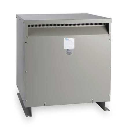
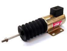
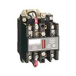
88 Basic Load Type Resistance, Inductance, Capacitance Examples of Inductive Loads are: Motors xfmr solenoid Relays and Contactors
89 Basic Load Type ELI the ICE man We have studied three types of loads on an electrical circuit. These loads are?
90 Basic Load Type ELI the ICE man We have studied three types of loads on an electrical circuit. These loads are? 1. Resistive 2. Capacitive 3. Inductive
91 Basic Load Type ELI the ICE man 1. Resistive 2. Capacitive 3. Inductive
92 Basic Load Type ELI the ICE man ELI the ICE man is a mnemonic that helps to remember the PHASE RELATIONSHIP Between CURRENT and VOLTAGE in inductive and capacitive circuits.
93 Basic Load Type ELI the ICE man A mnemonic is: a device such as a pattern of letters, ideas, or associations that assists in remembering something.
94 INDUCTIVE AC circuit CAPACITIVE AC circuit Alternating Current Study Guide Basic Load Type ELI the ICE man
95 Basic Load Type ELI the ICE man ELI the ICE man is a mnemonic that aids in remembering the phase relationship between the voltage and current in an AC circuit. E = voltage L = Inductance I = Current (electromotive force, measured in volts) (L is used due to Heinrich Lenz, measured in henrys) (intensité de courant French, measured in amps) C= Capacitance (F is used indicating farads, measure in farads.
96 Basic Load Type ELI the ICE man In an inductive circuit ELI the ICE man Voltage leads Current E = voltage L = Inductance I = Current (electromotive force, measured in volts) (L is used due to Heinrich Lenz, measured in henrys) (intensité de courant French, measured in amps) C= Capacitance (F is used indicating farads, measure in farads.
97 Basic Load Type ELI the ICE man In an capacitive circuit ELI the ICE man Current leads Voltage E = voltage L = Inductance I = Current (electromotive force, measured in volts) (L is used due to Heinrich Lenz, measured in henrys) (intensité de courant French, measured in amps) C= Capacitance (F is used indicating farads, measure in farads.
98 INDUCTIVE AC circuit CAPACITIVE AC circuit Alternating Current Study Guide Basic Load Type ELI the ICE man
99 RESISTIVE AC circuit Alternating Current Study Guide Basic Load Type ELI the ICE man
100 RESISTIVE AC circuit Alternating Current Study Guide Basic Load Type ELI the ICE man So ELI the ICE man has no application to RESISTIVE circuits because the relationship between voltage and current is IN PHASE.
101 RESISTIVE AC circuit Alternating Current Study Guide Basic Load Type ELI the ICE man So ELI the ICE man has no application to RESISTIVE circuits because the relationship between voltage and current is IN PHASE.
102 Basic Load Type ELI the ICE man Finally, remember: An inductor opposes changes is current. A capacitor opposes changes in voltage. ELI the ICE man help you to remember this, too! The current follows the voltage because the INDUCTOR opposes a change in current. The voltage follows the current because the CAPACITOR opposes a change in voltage.
103 QUIZ 1 Three Types of Loads 1. What does the E the L and the I stand for in ELI the ICE man? 2. What are the three types of circuit loads discussed in this module 3. Each of six equal capacitors in series has the applied voltage? a times b. 6 times c. 1/6 d Write the formula for capacitive reactance: 5. What is the numeric value of pi (Π)?
104 QUIZ 1 Three Types of Loads 1. What does the E the L and the I stand for in ELI the ICE man? E = voltage, I = current, L = inductive circuit 2. What are the three types of circuit loads discussed in this module Resistive, Capacitive, Inductive 3. Each of six equal capacitors in series has the applied voltage? a times b. 6 times c. 1/6 d Write the formula for capacitive reactance: 5. What is the numeric value of pi (Π)? 3.14 or
105 QUIZ 2 Three Types of Loads 1. What does the I the C and the E stand for in ELI the ICE man? 2. Write the formula for inductive reactance. 3. Based on the formula for inductive reactance, what increases inductive reactance. 4. Current leads the voltage in what type of circuit? 5. Current and voltage are in phase in what type of circuit?
106 QUIZ 2 Three Types of Loads 1. What does the I the C and the E stand for in ELI the ICE man? I = current, C = capacitive circuit, E = voltage 2. Write the formula for inductive reactance. 3. Based on the formula for inductive reactance, what increases inductive reactance. Frequency (f) and inductance (L) 4. Current leads the voltage in what type of circuit? Capacitive.ELI the ICE man 5. Current and voltage are in phase in what type of circuit? Resistive
107 QUIZ 3 Three Types of Loads 1. In a capacitive circuit the current leads the voltage? True/False 2. In a inductive circuit, the voltage leads the current? True/False 3. Based on the formula for inductive reactance, what increases inductive reactance. 4. If the area of capacitor plates are increased, the capacitance. Increases/Decreases 5. ELI the ICE man helps to remember the phase relationships between current and voltage in resistive circuits and inductive circuits. True/False
108 QUIZ 3 Three Types of Loads 1. In a capacitive circuit the current leads the voltage? True/False True ICE 2. In a inductive circuit, the voltage leads the current? True/False True ELI 3. Based on the formula for inductive reactance, what increases inductive reactance. Frequency and inductance 4. If the area of capacitor plates are increased, the capacitance. Increases/Decreases Increases 5. ELI the ICE man helps to remember the phase relationships between current and voltage in resistive circuits and inductive circuits. True/False between current and voltage in an inductive circuit and a capacitive circuit.
109 QUIZ 4 Three Types of Loads 1. Write Ohm s Law 2. Given: An AC circuit containing resistance only. What is the voltage if the resistance is 4 ohms and the current is 60 amps? 3. Given: An AC circuit containing resistance only. What is the current flow if the resistance is 8 ohms and the voltage is 120 volts? 4. If the distance between capacitor plates is increased, the capacitance. Increases/Decreases
110 QUIZ 4 Three Types of Loads 1. Write Ohm s Law E = IR 2. Given: An AC circuit containing resistance only. What is the voltage if the resistance is 4 ohms and the current is 60 amps? E = 4 x 60 = 240V 3. Given: An AC circuit containing resistance only. What is the current flow if the resistance is 8 ohms and the voltage is 120 volts? E/R = 120/8 = 15A 4. If the distance between capacitor plates is increased, the capacitance. Increases/Decreases
111 QUIZ 5 Three Types of Loads 1. Write the formula for capacitive reactance. 2. Based on the formula for capacitive reactance, what factors will increase capacitive reactance? 3. Find C T for two capacitors in parallel. Capacitor One = 4 μf and Capacitor Two = 4 μf. 4. Find C T for two capacitors in series. Capacitor One = 4 μf and Capacitor Two = 4 μf.
112 QUIZ 5 Three Types of Loads 1. Write the formula for capacitive reactance. 2. Based on the formula for capacitive reactance, what factors will increase capacitive reactance? Decrease frequency, decrease capacitance 3. Find C T for two capacitors in parallel. Capacitor One = 4 μf and Capacitor Two = 4 μf. 4. Find C T for two capacitors in series. Capacitor One = 4 μf and Capacitor Two = 4 μf. 4 μf + 4 μf = 8 μf Product Over Sum: (4x4) / (4 + 4) = 16 / 8 = 2 μf Capacitors of Equal Value: C/N = 4 / 2 = 2 μf Reciprocal Method: = 1 / ((1/4) + (1/4)) = 1 / (1/2) = 2 μf
113 Basic Load Type Power Triangle and Power Factor (True) The Power Triangle
114 Basic Load Type Power Triangle and Power Factor (True) The Power Triangle This is a vector diagram. The length of the vectors represent the magnitude.
 Trains prefer to travel on flat tracks. (The t-r in trains help to remember t-r in True Power.")
115 Basic Load Type Power Triangle and Power Factor Here is how I remember the triangle. It s stupid but it helps me remember. Sometimes a train has to Ascend a mountain. Ascend helps to remember Apparent Power. (True) Trains prefer to travel on flat tracks. (The t-r in trains help to remember t-r in True Power. Flat tracks helps to remember level line of triangle A train can never Rise straight up a mountain. Rise helps to remember Reactive Power.
116 Basic Load Type Power Triangle and Power Factor POWER FACTOR (True) 1. The power company makes VA 3. This is what we use after the reactance affects the supply. 2. Because of all the inductive loads and capacitive loads, there is some level of reactance causing a loss of efficiency
117 Basic Load Type Power Triangle and Power Factor POWER FACTOR (True) 1. The power company makes VA 3. This is what we use after the reactance affects the supply. PF = P True P Apparent 2. Because of all the inductive loads and capacitive loads, there is some level of reactance causing a loss of efficiency creating all of these electro-magnetic fields is necessary to perform work, but the magnetic fields don t actually do work.
118 Basic Load Type Power Triangle and Power Factor POWER FACTOR PF = P T P A This is an efficiency ratio. The value will e between 0 and 1. Of course 1 is perfect efficiency. Facilities try to target 0.9 or better. As the customer you want good efficiency because you are paying for P A and your getting P T as your output. Also the power company is going to start charging you a premium to clean up all the reactive power effects. Low PF is a double whammy!
119 QUIZ 1 Power Triangle and Power Factor 1. Draw the Power Triangle, showing what each of the three sides represents. 2. Reactive Power is greater than Apparent Power. True/False 3. True, or Real Power, is greater than Apparent Power. True/False 4. Power = I 2 R is the formula for a. True, or Real Power. b. Reactive Power. c. Apparent Power. d. Super Power
120 QUIZ 1 Power Triangle and Power Factor 1. Draw the Power Triangle, showing what each of the three sides represents. 2. Reactive Power is greater than Apparent Power. True/False Apparent is the hypotenuse, it will always be biggest 3. True, or Real Power, is greater than Apparent Power. True/False Apparent is the hypotenuse, it will always be biggest (True) 4. Power = I 2 R is the formula for a. True, or Real Power. b. Reactive Power. c. Apparent Power. d. Super Power
121 QUIZ 2 Power Triangle and Power Factor 1. What does PF stand for? 2. The ratio of Power to Apparent Power is called Power Factor? 3. Apparent Power is greater than Real, or True, Power True/False 4. Power = IE is the formula for a. True, or Real Power. b. Reactive Power. c. Apparent Power. d. Super Power
122 QUIZ 2 Power Triangle and Power Factor 1. What does PF stand for? POWER FACTOR REAL/TRUE 2. The ratio of Power to Apparent Power is called Power Factor? 3. Apparent Power is greater than Real, or True, Power True/False 4. Power = IE is the formula for a. True, or Real Power. b. Reactive Power. c. Apparent Power. d. Super Power
123 Transformers Let s think about what a transformer is. In your NCCER text a transformer is defined as: - A device that transforms electrical energy from one circuit to another by electromagnetic induction. The energy is transferred WITHOUT a change in frequency. If the primary circuit is 60Hz the secondary circuit is 60Hz. The Frequency is constant. However, the CURRENT and VOLTAGE do usually change when the energy is transferred in the transformer. In fact, most of the time when we install a transformer, it is primarily to change high voltage to lower voltage for things like receptacle panels.
124 Transformers Look at this basic transformer figure. Let s assume the first circuit is 480V (primary winding) and the other circuit (the secondary winding) will be a lower voltage, say 120V or 240V or 208V. We typically install a transformer because at some source we have a voltage too high for the load, so we have to transfer this electrical energy to a separate circuit (via electromagnetic induction (the transformer s job) to another, usually lower voltage, circuit.
125 Transformers Look at this basic transformer figure. Let s assume the first circuit is 480V (primary winding) and the other circuit (the secondary winding) will be a lower voltage, say 120V or 240V or 208V. We typically install a transformer because at some source we have a voltage too high for the load, so we have to transfer this electrical energy to a separate circuit (via electromagnetic induction (the transformer s job) to another, usually lower voltage, circuit. Secondary Circuit Primary Circuit TWO separate circuits
126 Transformers Look at this basic transformer figure. Let s assume the first circuit is 480V (primary winding) and the other circuit (the secondary winding) will be a lower voltage, say 120V or 240V or 208V. We typically install a transformer because at some source we have a voltage too high for the load, so we have to transfer this electrical energy to a separate circuit (via electromagnetic induction (the transformer s job) to another, usually lower voltage, circuit. 60 Hz 60 Hz Frequency is constant
127 Transformers Lower Voltage 208V Higher current 208A High voltage 480V Lower current 90A STEP-DOWN xfmr Typically installed for our field work
128 Transformers Lower Voltage 208V Higher current 208A High voltage 480V Lower current 90A STEP-DOWN xfmr Typically installed for our field work I P E POWER IS CONSTANT. The power provided by the primary circuit is equal to the power provided by the secondary circuit. Power = Volts x Amps 75,000 VA on primary side is equal to 75,000 VA on secondary side. This is a 75kVA transformer.
129 Transformers Secondary winding will always go to the electrical LOAD. Primary winding will always be from the electrical SOURCE.
130 Transformers - VOLTAGE RELATIONSHIP Not every transformer is a STEP-DOWN. You can have a STEP-UP transformer. High voltage at primary STEPPED DOWN to lower voltage at secondary. Low voltage at primary STEPPED UP to higher voltage at secondary.` Don t assume you can wire a transformer backwards to use lower voltage primary to get higher voltage secondary. The transformer has to be a STEP-UP or a regular transformer has to be REVERSE FEED CAPABLE
131 Voltage Alternating Current Study Guide Transformers PHASE RELATIONSHIP Some Transformers have the primary and secondary voltage IN PHASE. These are called LIKE-WOUND transformers 480V 208V Time

132 Voltage Alternating Current Study Guide Transformers PHASE RELATIONSHIP Some Transformers have the primary and secondary voltage 180 degrees out of phase. These are called UNLIKE-WOUND transformers 480V 208V Time
133 Transformers Turns and Turns Ratio The turns ratio affects the change in voltage from the primary side to the secondary side. In the turns ratio, the primary turns are always listed first, than the secondary turns. So using the figure below the turns ratio would be 10:5 (or reduce to 2:1) 5 Turns 10 Turns
134 Transformers - Turns and Turns Ratio The voltage change is directly proportional to this turns ratio. So in the figure below, with a 2:1 turns ratio, if the primary voltage was 120V what would the secondary voltage be? 5 Turns 10 Turns

135 Transformers Turns and Turns Ratio The voltage change is directly proportional to this turns ratio. So in the figure below, with a 2:1 turns ratio, if the primary voltage was 120V what would the secondary voltage be? 60V 5 Turns 10 Turns
136 Transformers Special Types Isolation Transformer Autotransformer Current Transformer
137 Transformers Special Types Isolation Transformer Autotransformer Current Transformers (one xfmr on each phase)


138 Transformers Special Types Current Transformer = CT


139 Transformers Special Types CTs which will feed a ammeter. CT Cabinet

140 Transformers Special Types More typical mounting of CTs for service conductors note that the CTs are hard-mounted and not floating. (sorry, best picture we could find for now.)
141 QUIZ 1 1. Electricity from the power source connects at the windings. Electricity from the windings goes out to the load. 2. A is a device that transforms electrical energy from one circuit to another by electromagnetic induction. 3. Frequency is the (same/different) at the primary and secondary windings of a transformer. 4. Transformers work via e i (aka transformer action).
142 QUIZ 1 primary 1. Electricity from the power source connects at the windings. secondary Electricity from the windings goes out to the load. transformer 2. A is a device that transforms electrical energy from one circuit to another by electromagnetic induction. 3. Frequency is the (same/different) at the primary and secondary windings of a transformer. 4. Transformers work via electro-magnetic induction (aka transformer action).
143 QUIZ 2 1. A transformer has a 4:1 turns ratio. The secondary voltage is 75V. What is the primary voltage. 2. In transformers turn ratios, the is always the first number in the ratio. 3. A transformer has a 3:1 turns ratio. The primary voltage is 75V. What is the secondary voltage. 4. It is not recommended to open a CT s secondary when the primary is under load - true/false
144 QUIZ 2 1. A transformer has a 4:1 turns ratio. The secondary voltage is 75V. What is the primary voltage. 300V primary 2. In transformers turn ratios, the is always the first number in the ratio. 3. A transformer has a 3:1 turns ratio. The primary voltage is 75V. What is the secondary voltage. 25V 4. It is not recommended to open a CT s secondary when the primary is under load - true/false
145 QUIZ 3 1. We typically install a step- transformer in the field to change the primary voltage of 480V down to a 208/120V panel. 2. A facility has a 208V service. A 480V HVAC unit has been installed. To supply the new unit with 480V you will need either a step- transformer or a properly sized reverse capable xfmr. 3. A given transformer has the following phase relationship: when the primary is +480V the secondary is Based on this phase relationship, what type of transformer is this: - wound. 4. A current transformer is also known as a (two letters).
146 QUIZ 3 1. We typically install a step- down transformer in the field to change the primary voltage of 480V down to a 208/120V panel. 2. A facility has a 208V service. A 480V HVAC unit has been installed. To supply the new unit with 480V you will need either a step- up transformer or a properly sized reverse feed capable xfmr. 3. A given transformer has the following phase relationship: when the primary is +480V the secondary is Based on this phase relationship, what type of transformer is this: like - wound. CT 4. A current transformer is also known as a (two letters).
147 QUIZ 4 1. There are three phase conductors for a service for a given facility. The service is active and loaded. What would happen if you were to remove the secondary wires from one of the CTs while it was under load? A dangerously high would likely occur.
148 QUIZ 4 1. There are three phase conductors for a service for a given facility. The service is active and loaded. What would happen if you were to remove the secondary wires from one of the CTs while it was under load? voltage A dangerously high would likely occur.
149 QUIZ 5 1. Based on figure below, these voltage curves indicate a step-up or step-down transformer? 2. Based on the figure below, these voltage curves indicate a like-wound or unlike-wound transformer?

150 QUIZ 5 1. Based on figure below, these voltage curves indicate a step-up or step-down transformer? Step-up (aka Buck and Boost 2. Based on the figure below, these voltage curves indicate a like-wound or unlike-wound transformer? unlike wound
Alternating Current Page 1 30
 Alternating Current 26201 11 Page 1 30 Calculate the peak and effective voltage of current values for AC Calculate the phase relationship between two AC waveforms Describe the voltage and current phase
Chapter 11. Alternating Current
 Unit-2 ECE131 BEEE Chapter 11 Alternating Current Objectives After completing this chapter, you will be able to: Describe how an AC voltage is produced with an AC generator (alternator) Define alternation,
Table of Contents. Introduction...2 Conductors and Insulators...3 Current, Voltage, and Resistance...6
 Table of Contents Introduction...2 Conductors and Insulators...3 Current, Voltage, and Resistance...6 Ohm s Law... 11 DC Circuits... 13 Magnetism...20 Alternating Current...23 Inductance and Capacitance...30
Bakiss Hiyana binti Abu Bakar JKE, POLISAS BHAB
 1 Bakiss Hiyana binti Abu Bakar JKE, POLISAS 1. Explain AC circuit concept and their analysis using AC circuit law. 2. Apply the knowledge of AC circuit in solving problem related to AC electrical circuit.
Electrical Theory. Power Principles and Phase Angle. PJM State & Member Training Dept. PJM /22/2018
 Electrical Theory Power Principles and Phase Angle PJM State & Member Training Dept. PJM 2018 Objectives At the end of this presentation the learner will be able to: Identify the characteristics of Sine
Unit 3 Magnetism...21 Introduction The Natural Magnet Magnetic Polarities Magnetic Compass...21
 Chapter 1 Electrical Fundamentals Unit 1 Matter...3 Introduction...3 1.1 Matter...3 1.2 Atomic Theory...3 1.3 Law of Electrical Charges...4 1.4 Law of Atomic Charges...4 Negative Atomic Charge...4 Positive
Preface...x Chapter 1 Electrical Fundamentals
 Preface...x Chapter 1 Electrical Fundamentals Unit 1 Matter...3 Introduction...3 1.1 Matter...3 1.2 Atomic Theory...3 1.3 Law of Electrical Charges...4 1.4 Law of Atomic Charges...5 Negative Atomic Charge...5
QUESTION BANK ETE (17331) CM/IF. Chapter1: DC Circuits
 CM/IF. Chapter1: DC Circuits") QUESTION BANK ETE (17331) CM/IF Chapter1: DC Circuits Q1. State & explain Ohms law. Also explain concept of series & parallel circuit with the help of diagram. 3M Q2. Find the value of resistor in fig.
QUESTION BANK ETE (17331) CM/IF Chapter1: DC Circuits Q1. State & explain Ohms law. Also explain concept of series & parallel circuit with the help of diagram. 3M Q2. Find the value of resistor in fig.
Question Paper Profile
 I Scheme Question Paper Profile Program Name : Electrical Engineering Program Group Program Code : EE/EP/EU Semester : Third Course Title : Electrical Circuits Max. Marks : 70 Time: 3 Hrs. Instructions:
An induced emf is the negative of a changing magnetic field. Similarly, a self-induced emf would be found by
 This is a study guide for Exam 4. You are expected to understand and be able to answer mathematical questions on the following topics. Chapter 32 Self-Induction and Induction While a battery creates an
SECTION 3 BASIC AUTOMATIC CONTROLS UNIT 12 BASIC ELECTRICITY AND MAGNETISM. Unit Objectives. Unit Objectives 2/29/2012
 SECTION 3 BASIC AUTOMATIC CONTROLS UNIT 12 BASIC ELECTRICITY AND MAGNETISM Unit Objectives Describe the structure of an atom. Identify atoms with a positive charge and atoms with a negative charge. Explain
Electrical Theory 2 Lessons for Fall Semester:
 Electrical Theory 2 Lessons for Fall Semester: Lesson 1 Magnetism Lesson 2 Introduction to AC Theory Lesson 3 Lesson 4 Capacitance and Capacitive Reactance Lesson 5 Impedance and AC Circuits Lesson 6 AC
Chapter 33. Alternating Current Circuits
 Chapter 33 Alternating Current Circuits Alternating Current Circuits Electrical appliances in the house use alternating current (AC) circuits. If an AC source applies an alternating voltage to a series
Basics of Electricity
 Basics of Electricity A quickstep Online Course Siemens industry, Inc. www.usa.siemens.com/step Trademarks Siemens is a trademark of Siemens AG. Product names mentioned may be trademarks or registered
CHAPTER 5 CONCEPTS OF ALTERNATING CURRENT
 CHAPTER 5 CONCEPTS OF ALTERNATING CURRENT INTRODUCTION Thus far this text has dealt with direct current (DC); that is, current that does not change direction. However, a coil rotating in a magnetic field
END-OF-SUBCOURSE EXAMINATION
 END-OF-SUBCOURSE EXAMINATION Circle the letter of the correct answer to each question. When you have answered all of the questions, use a Number 2 pencil to transfer your answers to the TSC Form 59. 1.
PHYS 1442 Section 004 Lecture #15
 PHYS 1442 Section 004 Lecture #15 Monday March 17, 2014 Dr. Andrew Brandt Chapter 21 Generator Transformer Inductance 3/17/2014 1 PHYS 1442-004, Dr. Andrew Brandt Announcements HW8 on Ch 21-22 will be
ELECTROMAGNETIC INDUCTION AND ALTERNATING CURRENT (Assignment)
") ELECTROMAGNETIC INDUCTION AND ALTERNATING CURRENT (Assignment) 1. In an A.C. circuit A ; the current leads the voltage by 30 0 and in circuit B, the current lags behind the voltage by 30 0. What is the
ELECTROMAGNETIC INDUCTION AND ALTERNATING CURRENT (Assignment) 1. In an A.C. circuit A ; the current leads the voltage by 30 0 and in circuit B, the current lags behind the voltage by 30 0. What is the
Introduction. Upon completion of Basics of Electricity you will be able to: Explain the difference between conductors and insulators
 Table of Contents Introduction...2 Electron Theory...4 Conductors, Insulators and Semiconductors...5 Electric Charges...7 Current...9 Voltage... 11 Resistance... 13 Simple Electric Circuit... 15 Ohm s
Chapt ha e pt r e r 11 Inductors
 Chapter 11 Inductors The Basic Inductor When a length of wire is formed onto a coil, it becomes a basic inductor Magnetic lines of force around each loop in the winding of the coil effectively add to the
Lab #5 ENG RC Circuits
 Name:. Lab #5 ENG 220-001 Date: Learning objectives of this experiment is that students will be able to: Measure the effects of frequency upon an RC circuit Calculate and understand circuit current, impedance,
Inductance, capacitance and resistance
 Inductance, capacitance and resistance As previously discussed inductors and capacitors create loads on a circuit. This is called reactance. It varies depending on current and frequency. At no frequency,
Look over Chapter 31 sections 1-4, 6, 8, 9, 10, 11 Examples 1-8. Look over Chapter 21 sections Examples PHYS 2212 PHYS 1112
 PHYS 2212 Look over Chapter 31 sections 1-4, 6, 8, 9, 10, 11 Examples 1-8 PHYS 1112 Look over Chapter 21 sections 11-14 Examples 16-18 Good Things To Know 1) How AC generators work. 2) How to find the
AC Theory, Circuits, Generators & Motors
 PDH-Pro.com AC Theory, Circuits, Generators & Motors Course Number: EE-02-306 PDH: 6 Approved for: AK, AL, AR, GA, IA, IL, IN, KS, KY, MD, ME, MI, MN, MO, MS, MT, NC, ND, NE, NH, NJ, NM, NV, OH, OK, OR,
Alternating current circuits- Series RLC circuits
 FISI30 Física Universitaria II Professor J.. ersosimo hapter 8 Alternating current circuits- Series circuits 8- Introduction A loop rotated in a magnetic field produces a sinusoidal voltage and current.
ET1210: Module 5 Inductance and Resonance
 Part 1 Inductors Theory: When current flows through a coil of wire, a magnetic field is created around the wire. This electromagnetic field accompanies any moving electric charge and is proportional to
ENGINEERING COUNCIL CERTIFICATE LEVEL ENGINEERING SCIENCE C103 TUTORIAL 18 ALTERNATING CURRENT
 ENGINEERING OUNIL ERTIFIATE LEVEL ENGINEERING SIENE 03 TUTORIAL 8 ALTERNATING URRENT On completion of this tutorial you should be able to do the following. Explain alternating current. Explain Root Mean
SIDDHARTH GROUP OF INSTITUTIONS :: PUTTUR (AUTONOMOUS) Siddharth Nagar, Narayanavanam Road QUESTION BANK (DESCRIPTIVE) UNIT I INTRODUCTION
 Siddharth Nagar, Narayanavanam Road QUESTION BANK (DESCRIPTIVE) UNIT I INTRODUCTION") SIDDHARTH GROUP OF INSTITUTIONS :: PUTTUR (AUTONOMOUS) Siddharth Nagar, Narayanavanam Road 517583 QUESTION BANK (DESCRIPTIVE) Subject with Code : Electrical Circuits(16EE201) Year & Sem: I-B.Tech & II-Sem
SIDDHARTH GROUP OF INSTITUTIONS :: PUTTUR (AUTONOMOUS) Siddharth Nagar, Narayanavanam Road 517583 QUESTION BANK (DESCRIPTIVE) Subject with Code : Electrical Circuits(16EE201) Year & Sem: I-B.Tech & II-Sem
Review 6. unlike poles cause the magnets to attract. like poles cause the magnets to repel.
 Review 6 1. The two characteristics of all magnets are: they attract and hold Iron, and, if free to move, they will assume roughly a south - north position. 2. Lines of flux always leave the north pole
Downloaded from / 1
 PURWANCHAL UNIVERSITY II SEMESTER FINAL EXAMINATION-2008 LEVEL : B. E. (Computer/Electronics & Comm.) SUBJECT: BEG123EL, Electrical Engineering-I Full Marks: 80 TIME: 03:00 hrs Pass marks: 32 Candidates
Chapter 28 Alternating Current Circuits
 History teaches us that the searching spirit of man required thousands of years for the discovery of the fundamental principles of the sciences, on which the superstructure was then raised in a comparatively
Chapter 6: Alternating Current. An alternating current is an current that reverses its direction at regular intervals.
 Chapter 6: Alternating Current An alternating current is an current that reverses its direction at regular intervals. Overview Alternating Current Phasor Diagram Sinusoidal Waveform A.C. Through a Resistor
Chapter 30 Inductance, Electromagnetic. Copyright 2009 Pearson Education, Inc.
 Chapter 30 Inductance, Electromagnetic Oscillations, and AC Circuits 30-7 AC Circuits with AC Source Resistors, capacitors, and inductors have different phase relationships between current and voltage
SHRI RAMSWAROOP MEMORIAL COLLEGE OF ENGG. & MANAGEMENT B.Tech. [SEM I (EE, EN, EC, CE)] QUIZ TEST-3 (Session: ) Time: 1 Hour ELECTRICAL ENGINEE
![SHRI RAMSWAROOP MEMORIAL COLLEGE OF ENGG. & MANAGEMENT B.Tech. [SEM I (EE, EN, EC, CE)] QUIZ TEST-3 (Session: ) Time: 1 Hour ELECTRICAL ENGINEE](/thumbs/94/118213481.jpg "SHRI RAMSWAROOP MEMORIAL COLLEGE OF ENGG. & MANAGEMENT B.Tech. [SEM I (EE, EN, EC, CE)] QUIZ TEST-3 (Session: ) Time: 1 Hour ELECTRICAL ENGINEE") SHRI RAMSWAROOP MEMORIAL COLLEGE OF ENGG. & MANAGEMENT B.Tech. [SEM I (EE, EN, EC, CE)] QUIZ TEST-3 (Session: 2014-15) Time: 1 Hour ELECTRICAL ENGINEERING Max. Marks: 30 (NEE-101) Roll No. Academic/26
SHRI RAMSWAROOP MEMORIAL COLLEGE OF ENGG. & MANAGEMENT B.Tech. [SEM I (EE, EN, EC, CE)] QUIZ TEST-3 (Session: 2014-15) Time: 1 Hour ELECTRICAL ENGINEERING Max. Marks: 30 (NEE-101) Roll No. Academic/26
Chapter 33. Alternating Current Circuits
 Chapter 33 Alternating Current Circuits C HAP T E O UTLI N E 33 1 AC Sources 33 2 esistors in an AC Circuit 33 3 Inductors in an AC Circuit 33 4 Capacitors in an AC Circuit 33 5 The L Series Circuit 33
Chapter Moving Charges and Magnetism
 100 Chapter Moving Charges and Magnetism 1. The power factor of an AC circuit having resistance (R) and inductance (L) connected in series and an angular velocity ω is [2013] 2. [2002] zero RvB vbl/r vbl
AP Physics C. Alternating Current. Chapter Problems. Sources of Alternating EMF
 AP Physics C Alternating Current Chapter Problems Sources of Alternating EMF 1. A 10 cm diameter loop of wire is oriented perpendicular to a 2.5 T magnetic field. What is the magnetic flux through the
Trade of Electrician. Introduction to AC
 Trade of Electrician Standards Based Apprenticeship Introduction to AC Phase 2 Module No. 2.1 Unit No. 2.1.9 COURSE NOTES Created by Gerry Ryan - Galway TC Revision 1. April 2000 by Gerry Ryan - Galway
AC Fundamental. Simple Loop Generator: Whenever a conductor moves in a magnetic field, an emf is induced in it.
 AC Fundamental Simple Loop Generator: Whenever a conductor moves in a magnetic field, an emf is induced in it. Fig.: Simple Loop Generator The amount of EMF induced into a coil cutting the magnetic lines
Chapter 25 Alternating Currents
 Chapter 25 Alternating Currents GOALS When you have mastered the contents of this chapter, you will be able to achieve the following goals: Definitions Define each of the following terms and use it in
1. If the flux associated with a coil varies at the rate of 1 weber/min,the induced emf is
 1. f the flux associated with a coil varies at the rate of 1 weber/min,the induced emf is 1 1. 1V 2. V 60 3. 60V 4. Zero 2. Lenz s law is the consequence of the law of conservation of 1. Charge 2. Mass
Goals. Introduction. To understand the use of root mean square (rms) voltages and currents.
 voltages and currents.") Lab 10. AC Circuits Goals To show that AC voltages cannot generally be added without accounting for their phase relationships. That is, one must account for how they vary in time with respect to one another.
Lab 10. AC Circuits Goals To show that AC voltages cannot generally be added without accounting for their phase relationships. That is, one must account for how they vary in time with respect to one another.
K6RIA, Extra Licensing Class. Circuits & Resonance for All!
 K6RIA, Extra Licensing Class Circuits & Resonance for All! Amateur Radio Extra Class Element 4 Course Presentation ELEMENT 4 Groupings Rules & Regs Skywaves & Contesting Outer Space Comms Visuals & Video
Goals. Introduction. To understand the use of root mean square (rms) voltages and currents.
 voltages and currents.") Lab 10. AC Circuits Goals To show that AC voltages cannot generally be added without accounting for their phase relationships. That is, one must account for how they vary in time with respect to one another.
Lab 10. AC Circuits Goals To show that AC voltages cannot generally be added without accounting for their phase relationships. That is, one must account for how they vary in time with respect to one another.
Lesson 3: Electronics & Circuits
 Lesson 3: Electronics & Circuits Preparation for Amateur Radio Technician Class Exam Topics Review Ohm s Law Energy & Power Circuits Inductors & Inductance Capacitors & Capacitance Analog vs Digital Exam
Basic Analog Circuits
 Basic Analog Circuits Overview This tutorial is part of the National Instruments Measurement Fundamentals series. Each tutorial in this series, will teach you a specific topic of common measurement applications,
Ac fundamentals and AC CIRCUITS. Q1. Explain and derive an expression for generation of AC quantity.
 Ac fundamentals and AC CIRCUITS Q1. Explain and derive an expression for generation of AC quantity. According to Faradays law of electromagnetic induction when a conductor is moving within a magnetic field,
Electromagnetic Induction - A
 Electromagnetic Induction - A APPARATUS 1. Two 225-turn coils 2. Table Galvanometer 3. Rheostat 4. Iron and aluminum rods 5. Large circular loop mounted on board 6. AC ammeter 7. Variac 8. Search coil
Chapter 6: Alternating Current
 hapter 6: Alternating urrent 6. Alternating urrent.o 6.. Define alternating current (A) An alternating current (A) is the electrical current which varies periodically with time in direction and magnitude.
A handy mnemonic (memory aid) for remembering what leads what is ELI the ICEman E leads I in an L; I leads E in a C.
 for remembering what leads what is ELI the ICEman E leads I in an L; I leads E in a C.") Amateur Extra Class Exam Guide Section E5A Page 1 of 5 E5A Resonance and Q: characteristics of resonant circuits: series and parallel resonance; Q; half-power bandwidth; phase relationships in reactive
Amateur Extra Class Exam Guide Section E5A Page 1 of 5 E5A Resonance and Q: characteristics of resonant circuits: series and parallel resonance; Q; half-power bandwidth; phase relationships in reactive
Aligarh College of Engineering & Technology (College Code: 109) Affiliated to UPTU, Approved by AICTE Electrical Engg.
 Affiliated to UPTU, Approved by AICTE Electrical Engg.") Aligarh College of Engineering & Technology (College Code: 19) Electrical Engg. (EE-11/21) Unit-I DC Network Theory 1. Distinguish the following terms: (a) Active and passive elements (b) Linearity and
Aligarh College of Engineering & Technology (College Code: 19) Electrical Engg. (EE-11/21) Unit-I DC Network Theory 1. Distinguish the following terms: (a) Active and passive elements (b) Linearity and
2.0 AC CIRCUITS 2.1 AC VOLTAGE AND CURRENT CALCULATIONS. ECE 4501 Power Systems Laboratory Manual Rev OBJECTIVE
 2.0 AC CIRCUITS 2.1 AC VOLTAGE AND CURRENT CALCULATIONS 2.1.1 OBJECTIVE To study sinusoidal voltages and currents in order to understand frequency, period, effective value, instantaneous power and average
CIRCLE DIAGRAMS. Learning Objectives. Combinations of R and C circuits
 H A P T E R18 earning Objectives ircle Diagram of a Series ircuit Rigorous Mathematical Treatment onstant Resistance but ariable Reactance Properties of onstant Reactance But ariable Resistance ircuit
Lab 1: Basic RL and RC DC Circuits
 Name- Surname: ID: Department: Lab 1: Basic RL and RC DC Circuits Objective In this exercise, the DC steady state response of simple RL and RC circuits is examined. The transient behavior of RC circuits
11. AC-resistances of capacitor and inductors: Reactances.
 11. AC-resistances of capacitor and inductors: Reactances. Purpose: To study the behavior of the AC voltage signals across elements in a simple series connection of a resistor with an inductor and with
WALJAT COLLEGES OF APPLIED SCIENCES In academic partnership with BIRLA INSTITUTE OF TECHNOLOGY Question Bank Course: EC Session:
 WLJT OLLEGES OF PPLIED SIENES In academic partnership with IRL INSTITUTE OF TEHNOLOGY Question ank ourse: E Session: 20052006 Semester: II Subject: E2001 asic Electrical Engineering 1. For the resistive
CHAPTER 2. Basic Concepts, Three-Phase Review, and Per Unit
 CHAPTER 2 Basic Concepts, Three-Phase Review, and Per Unit 1 AC power versus DC power DC system: - Power delivered to the load does not fluctuate. - If the transmission line is long power is lost in the
University of Jordan School of Engineering Electrical Engineering Department. EE 219 Electrical Circuits Lab
 University of Jordan School of Engineering Electrical Engineering Department EE 219 Electrical Circuits Lab EXPERIMENT 7 RESONANCE Prepared by: Dr. Mohammed Hawa EXPERIMENT 7 RESONANCE OBJECTIVE This experiment
Sirindhorn International Institute of Technology Thammasat University
 Sirindhorn International Institute of Technology Thammasat University School of Information, Computer and Communication Technology COURSE : ECS 34 Basic Electrical Engineering Lab INSTRUCTOR : Dr. Prapun
TRANSFORMER THEORY. Mutual Induction
 Transformers Transformers are used extensively for AC power transmissions and for various control and indication circuits. Knowledge of the basic theory of how these components operate is necessary to
MAHARASHTRA STATE BOARD OF TECHNICAL EDUCATION
 Important Instructions to examiners: 1. The answers should be examined by key words and not as word-to-word as given in the model answer scheme. 2. The model answer and the answer written by candidate
ECE 2006 University of Minnesota Duluth Lab 11. AC Circuits
 1. Objective AC Circuits In this lab, the student will study sinusoidal voltages and currents in order to understand frequency, period, effective value, instantaneous power and average power. Also, the
Introduction. Inductors in AC Circuits.
 Module 3 AC Theory What you ll learn in Module 3. Section 3.1 Electromagnetic Induction. Magnetic Fields around Conductors. The Solenoid. Section 3.2 Inductance & Back e.m.f. The Unit of Inductance. Factors
Experiment 45. Three-Phase Circuits. G 1. a. Using your Power Supply and AC Voltmeter connect the circuit shown OBJECTIVE
 Experiment 45 Three-Phase Circuits OBJECTIVE To study the relationship between voltage and current in three-phase circuits. To learn how to make delta and wye connections. To calculate the power in three-phase
AC Power Instructor Notes
 Chapter 7: AC Power Instructor Notes Chapter 7 surveys important aspects of electric power. Coverage of Chapter 7 can take place immediately following Chapter 4, or as part of a later course on energy
LCR CIRCUITS Institute of Lifelong Learning, University of Delhi
 L UTS nstitute of Lifelong Learning, University of Delhi L UTS PHYSS (LAB MANUAL) nstitute of Lifelong Learning, University of Delhi PHYSS (LAB MANUAL) L UTS ntroduction ircuits containing an inductor
EASY(ER) ELECTRICAL PRINCIPLES FOR GENERAL CLASS HAM LICENSE
 ELECTRICAL PRINCIPLES FOR GENERAL CLASS HAM LICENSE") EASY(ER) ELECTRICAL PRINCIPLES FOR GENERAL CLASS HAM LICENSE 2015-2019 Josip Medved 2015-05-28 FOREWORD Taking an exam in order to get a ham license is quite stressful ordeal as it comes. To make things
EASY(ER) ELECTRICAL PRINCIPLES FOR GENERAL CLASS HAM LICENSE 2015-2019 Josip Medved 2015-05-28 FOREWORD Taking an exam in order to get a ham license is quite stressful ordeal as it comes. To make things
Chapter 21. Alternating Current Circuits and Electromagnetic Waves
 Chapter 21 Alternating Current Circuits and Electromagnetic Waves AC Circuit An AC circuit consists of a combination of circuit elements and an AC generator or source The output of an AC generator is sinusoidal
Chapter 7. Copyright The McGraw-Hill Companies, Inc. Permission required for reproduction or display.
 Chapter 7 Copyright The McGraw-Hill Companies, Inc. Permission required for reproduction or display. Learning Objectives 1. Understand the meaning of instantaneous and average power, master AC power notation,
PHYSICS WORKSHEET CLASS : XII. Topic: Alternating current
 PHYSICS WORKSHEET CLASS : XII Topic: Alternating current 1. What is mean by root mean square value of alternating current? 2. Distinguish between the terms effective value and peak value of an alternating
Circuit Analysis-II. Circuit Analysis-II Lecture # 2 Wednesday 28 th Mar, 18
 Circuit Analysis-II Angular Measurement Angular Measurement of a Sine Wave ü As we already know that a sinusoidal voltage can be produced by an ac generator. ü As the windings on the rotor of the ac generator
AC CURRENTS, VOLTAGES, FILTERS, and RESONANCE
 July 22, 2008 AC Currents, Voltages, Filters, Resonance 1 Name Date Partners AC CURRENTS, VOLTAGES, FILTERS, and RESONANCE V(volts) t(s) OBJECTIVES To understand the meanings of amplitude, frequency, phase,
KINGS COLLEGE OF ENGINEERING DEPARTMENT OF ELECTRICAL AND ELECTRONICS ENGINEERING QUESTION BANK UNIT I BASIC CIRCUITS ANALYSIS PART A (2-MARKS)
") KINGS COLLEGE OF ENGINEERING DEPARTMENT OF ELECTRICAL AND ELECTRONICS ENGINEERING QUESTION BANK YEAR / SEM : I / II SUBJECT CODE & NAME : EE 1151 CIRCUIT THEORY UNIT I BASIC CIRCUITS ANALYSIS PART A (2-MARKS)
KINGS COLLEGE OF ENGINEERING DEPARTMENT OF ELECTRICAL AND ELECTRONICS ENGINEERING QUESTION BANK YEAR / SEM : I / II SUBJECT CODE & NAME : EE 1151 CIRCUIT THEORY UNIT I BASIC CIRCUITS ANALYSIS PART A (2-MARKS)
THE SINUSOIDAL WAVEFORM
 Chapter 11 THE SINUSOIDAL WAVEFORM The sinusoidal waveform or sine wave is the fundamental type of alternating current (ac) and alternating voltage. It is also referred to as a sinusoidal wave or, simply,
Exercise 9. Electromagnetism and Inductors EXERCISE OBJECTIVE DISCUSSION OUTLINE DISCUSSION. Magnetism, magnets, and magnetic field
 Exercise 9 Electromagnetism and Inductors EXERCISE OBJECTIVE When you have completed this exercise, you will be familiar with the concepts of magnetism, magnets, and magnetic field, as well as electromagnetism
ALTERNATING CURRENT. Lesson-1. Alternating Current and Voltage
 esson- ATENATING UENT Alternating urrent and oltage An alternating current or voltage is that variation of current or voltage respectively whose magnitude and direction vary periodically and continuously
N I N LI I. I t. (Note how L is independent of the current I.)
") UNIT- IV MAGNETICALLY COUPLED CIRCUITS Magnetically Coupled Circuits: Self inductance - Mutual inductance - Dot rule - Coefficient of coupling - Analysis of multi winding coupled circuits - Series, Parallel
UNIT- IV MAGNETICALLY COUPLED CIRCUITS Magnetically Coupled Circuits: Self inductance - Mutual inductance - Dot rule - Coefficient of coupling - Analysis of multi winding coupled circuits - Series, Parallel
Any wave shape can be reproduced by the sum of sine waves of the appropriate magnitude and frequency.
 How do we use an oscilloscope? Measure signals with unknown wave shapes and frequency other than 60 Hz sine waves and dc. To get a picture of the waveform. Distortion? Phase duration? Magnitude Any wave
SUBELEMENT T5 Electrical principles: math for electronics; electronic principles; Ohm s Law 4 Exam Questions - 4 Groups
 SUBELEMENT T5 Electrical principles: math for electronics; electronic principles; Ohm s Law 4 Exam Questions - 4 Groups 1 T5A Electrical principles, units, and terms: current and voltage; conductors and
University of Jordan School of Engineering Electrical Engineering Department. EE 219 Electrical Circuits Lab
 University of Jordan School of Engineering Electrical Engineering Department EE 219 Electrical Circuits Lab EXPERIMENT 4 TRANSIENT ANALYSIS Prepared by: Dr. Mohammed Hawa EXPERIMENT 4 TRANSIENT ANALYSIS
PART B. t (sec) Figure 1
 Figure 1") Code No: R16128 R16 SET 1 I B. Tech II Semester Regular Examinations, April/May 217 ELECTRICAL CIRCUIT ANALYSIS I (Electrical and Electronics Engineering) Time: 3 hours Max. Marks: 7 Note: 1. Question
Code No: R16128 R16 SET 1 I B. Tech II Semester Regular Examinations, April/May 217 ELECTRICAL CIRCUIT ANALYSIS I (Electrical and Electronics Engineering) Time: 3 hours Max. Marks: 7 Note: 1. Question
2π LC. = (2π) 2 4/30/2012. General Class Element 3 Course Presentation X C. Electrical Principles. ElectriElectrical Principlesinciples F 2 =
 2 4/30/2012. General Class Element 3 Course Presentation X C. Electrical Principles. ElectriElectrical Principlesinciples F 2 =") General Class Element 3 Course Presentation ti ELEMENT 3 SUB ELEMENTS General Licensing Class Subelement G5 3 Exam Questions, 3 Groups G1 Commission s Rules G2 Operating Procedures G3 Radio Wave Propagation
General Class Element 3 Course Presentation ti ELEMENT 3 SUB ELEMENTS General Licensing Class Subelement G5 3 Exam Questions, 3 Groups G1 Commission s Rules G2 Operating Procedures G3 Radio Wave Propagation
The G4EGQ RAE Course Lesson 4A AC theory
 AC. CIRCUITS This lesson introduces inductors into our AC. circuit. We then look at the result of having various combinations of capacitance, inductance and resistance in the same circuit. This leads us
VE7CNF - 630m Antenna Matching Measurements Using an Oscilloscope
 VE7CNF - 630m Antenna Matching Measurements Using an Oscilloscope Toby Haynes October, 2016 1 Contents VE7CNF - 630m Antenna Matching Measurements Using an Oscilloscope... 1 Introduction... 1 References...
Practical Tricks with Transformers. Larry Weinstein K0NA
 Practical Tricks with Transformers Larry Weinstein K0NA Practical Tricks with Transformers Quick review of inductance and magnetics Switching inductive loads How many voltages can we get out of a $10 Home
UEE11 Electrotechnology. Training Package
 UEE11 Electrotechnology Training Package UEENEEJ153A Find and rectify faults in motors and associated controls in refrigeration and air conditioning systems Learner Workbook Version 1 Training and Education
MECH 1100 Quiz 4 Practice
 Name: Class: Date: MECH 1100 Quiz 4 Practice True/False Indicate whether the statement is true or false. 1. An advantage of a of a three-phase induction motor is that it does not require starter windings.
Roeback s Final Project_EECT111
 Roeback s Final Project_EECT111 1 Using MultiSim, Excel and hand calculations create a set of notes that show how to: 1.) Combine multiple resistors in series and parallel. 2.) By example calculate RT,
AC Theory and Electronics
 AC Theory and Electronics An Alternating Current (AC) or Voltage is one whose amplitude is not constant, but varies with time about some mean position (value). Some examples of AC variation are shown below:
z z" z v 2 ft = 2k ft. 328 Concepts of Physics The energy dissipated in 1000 s = P * 1000 s
 38 Concepts of Physics. A series AC circuit contains an inductor ( mh), a capacitor ( (JF), a resistor ( ft) and an AC source of V, Hz. Find the energy dissipated in the circuit in s. Solution : The time
Inductance in DC Circuits
 Inductance in DC Circuits Anurag Srivastava Concept: Inductance is characterized by the behavior of a coil of wire in resisting any change of electric current through the coil. Arising from Faraday's law,
Transformers. gpmacademics.weebly.com
 TRANSFORMERS Syllabus: Principles of operation, Constructional Details, Losses and efficiency, Regulation of Transformer, Testing: OC & SC test. TRANSFORMER: It is a static device which transfers electric
Hours / 100 Marks Seat No.
 17323 14115 3 Hours / 100 Seat No. Instructions (1) All Questions are Compulsory. (2) Illustrate your answers with neat sketches wherever necessary. (3) Figures to the right indicate full marks. (4) Assume
A.C. Circuits -- Conceptual Solutions
 A.C. Circuits -- Conceptual Solutions 1.) Charge carriers in a DC circuit move in one direction only. What do charge carriers do in an AC circuit? Solution: The voltage difference between the terminals
Electromagnetic Induction
 Chapter 16 Electromagnetic Induction In This Chapter: Electromagnetic Induction Faraday s Law Lenz s Law The Transformer Self-Inductance Inductors in Combination Energy of a Current-Carrying Inductor Electromagnetic
BASIC ELECTRICAL AND INSTRUMENTATION DESIGN TRAINING SECTOR / ENGINEERING
 BASIC ELECTRICAL AND INSTRUMENTATION DESIGN TRAINING SECTOR / ENGINEERING TECHNICAL & CERTIFICATE OF ATTENDANCE TRAINING COURSE This five days course covers the electrical principles and components used
Electromagnetic Oscillations and Currents. March 23, 2014 Chapter 30 1
 Electromagnetic Oscillations and Currents March 23, 2014 Chapter 30 1 Driven LC Circuit! The voltage V can be thought of as the projection of the vertical axis of the phasor V m representing the time-varying
AC Basics - EM2 Competencies 1 Copyright 2017, ETA International, All Rights Reserved
 AC BASICS Electronics Module 2 (EM2) COMPETENCY REQUIREMENTS The five ETA Electronics Modules (EMs) are stand-alone certifications in five basic areas of electronics competency DC, AC, Analog, Digital,
EXPERIMENT 4: RC, RL and RD CIRCUITs
 EXPERIMENT 4: RC, RL and RD CIRCUITs Equipment List An assortment of resistor, one each of (330, 1k,1.5k, 10k,100k,1000k) Function Generator Oscilloscope 0.F Ceramic Capacitor 100H Inductor LED and 1N4001
Paper number: Principles of electrical and electronics technology Paper series: December Practice
 Paper number: 850-56 Paper series: December 04 Question Syllabus reference Question 0.0 a) i) Tesla. ii) Newton. iii) Henry. Marks mark each 4 0.0 0.0 0.0 i) Megavolt ii) Microvolt. a) Directly Inversely