WHAT ARE WE MEASURING?
|
|
|
- Stephen Fleming
- 5 years ago
- Views:
Transcription


1 WHAT ARE WE MEASURING? ASEG Workshop on Airborne Electromagnetics P th Perth November 7th 2012 P. Mutton, Consulting Geophysicist Southern Geoscience Consultants
2 WHAT ARE WE MEASURING? OUTLINE Electomagnetic Induction EM Survey technique Frequency and Time Domain Natural and Active Source Conductivity of Rocks Survey Signal Sources Conductive Earth Confined Conductors Ground Polarisation SPM


 Loop of wire (watch for")
3 INDUCED FIELDS Technique is an application Faraday s Law described with Maxwells equations Faraday s Law of Induction A changing magnetic field induces a current in a conductor Magnetic Field Lines Primary or inducing field Magnetic Field strength Induced delectric field strength (current flow) Loop of wire (watch for secondary fields)
4 INDUCED FIELDS Technique is an application Faraday s Law described with Maxwells equations Faraday s Law of Induction A changing magnetic field induces a current in a conductor Magnetic Field Lines Magnetic Field strength Loop of wire Induced delectric Field strength
5 AEM SURVEYING FREQUENCY AND TIME DOMAIN Measurements are completed in either FREQUENCY DOMAIN Measurements are of a limited number of frequencies (e.g. 5) Secondary field is described as an amplitude ( in phase ) and phase difference relative to the energising field ( quadrature ) TIME DOMAIN Current is turned on and off Energisation of the ground occurs as the current is turned on and off Measurement s are normally made of the decaying magnetic field after the primary current /magnetic field is off. in phase quadrature
6 EM SURVEYING FREQUENCY AND TIME DOMAIN Each frequency measured in a Frequency Domain survey has the same information as a single channel in a time domain survey... So there is much more conductivity information in any time domain EM reading than a FDEM reading. channel channel
 VLF transmitters (submarine communication)")
7 EM SURVEYING Our energising gfields for AEM surveys can be artificial or natural NATURAL SOURCE Lightning g g Sprites Solar wind Magnetosphere interactions ACTIVE SOURCE Current in a wire with aircraft (FD & TDEM) VLF transmitters (submarine communication) FD


8 EM SURVEYING NATURAL SOURCE Aircraft travels with a large coil sensor measuring the magnetic field at many (e.g. 5) different frequencies A stationary remote sensor measures the horizontal and vertical fields at the same frequencies The lower the frequency the deeper the information Inversion is often required to establish correct depths. Stationary sensor Exchange for AIRMT
9 EM SURVEYING ACTIVE SOURCE Aircraft travels with a wire loop/coil with varying current ( transmitter ) which generates a large magnetic field. A second coil of wire is used as the sensor ( receiver ) measure the changing field from currents induced in the earth (and primary field if it is on) Receiver is always towed by the aircraft and may be in or outside of the transmitter loop, above, or below it. ground Transmitter T i can be towed (llhem (all systems) or wrapped around nose, wings and tail of an aeroplane. ASEG AEM Workshop Perth November 2012
 measure the changing field from currents induced in the earth (and primary field if it is on) Receiver is always towed by the aircraft and may")
10 EM SURVEYING ACTIVE SOURCE Aircraft travels with a wire loop/coil with varying current ( transmitter ) which generates a large magnetic field. A second coil of wire is used as the sensor ( receiver ) measure the changing field from currents induced in the earth (and primary field if it is on) Receiver is always towed by the aircraft and may be in or outside of the transmitter loop, above, or below it. Transmitter can be towed (all HEM systems) or wrapped around nose, wings and tail of an aeroplane. ground
11 AEM SURVEYING CONDUCTIVE EARTH chalcocite pyrite pyrrhotite chalcopyrite 1kS/m 10kS/m 100kS/m After Palaky, massive sulphide range expanded Property we can measure is conductance (S) = conductivity (S/m) x thickness (m)
12 EM SURVEYING SIGNAL SOURCES Our transmitter signal fields (electric and magnetic) interact with the earth in a number of ways some of which we want and some of which we don t: WHAT WE WANT 1. Galvanic Currents: Inductive response from the ground (mapping, groundwater ) 2. Vortex Currents: Inductive response from discrete conductors (for Ni/Cu/Fe ore targets) WHAT WE DON T WANT 1. Ground polarisation effects 2. Superparamagentic effects 3. Noise (Spherics, Powerlines)
13 EM SURVEYING SIGNAL SOURCES Our transmitter signal fields (electric and magnetic) interact with the earth in a number of ways some of which we want and some of which we don t: WHAT WE WANT 1. Galvanic Currents: Inductive response from the ground (mapping, groundwater ) 2. Vortex Currents: Inductive response from discrete conductors (for Ni/Cu/Fe ore targets) WHAT WE DON T WANT 1. Ground polarisation effects 2. Superparamagentic effects 3. Noise (Spherics, Powerlines)


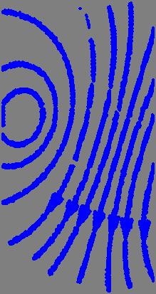
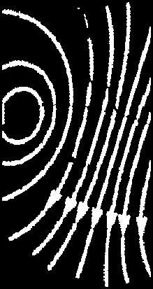
14 SIGNAL SOURCES CONDUCTIVE HOST ROCKS Pi Primary Magnetic Field! Rx Tx
15 SIGNAL SOURCES CONDUCTIVE HOST ROCKS Rx Tx Induced Currents!
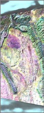
16 SIGNAL SOURCES CONDUCTIVE HOST ROCKS These currents move down rapidly in resistive ground and slowly in conductive ground. The rate that the signal drops off can be used to map the conductivity of the earth basis of Conductivity Depth Inversions. When the geology is layered and there are no lateral changes CDIs can map the earth very well. When the geology is not layered (eg: dipping strata, faults, folds, channels) the assumptions of the CDIs fail and so does the reliability of the inversions. 3D inversions are now possible but these are still slow and expensive.


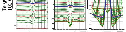
17 3km COMBINATION OF HOST AND CONFINED CONDUCTIVE RESPONSES Increasing channel/delay time Increasing depth of galvanic current systems
18 EM SURVEYING SIGNAL SOURCES Our transmitter signal fields (electric and magnetic) interact with the earth in a number of ways some of which we want and some of which we don t: WHAT WE WANT 1. Galvanic Currents: Inductive response from the ground (mapping, groundwater ) 2. Vortex Currents: Inductive response from discrete conductors (for Ni/Cu/Fe ore targets) WHAT WE DON T WANT 1. Ground polarisation effects 2. Superparamagentic effects 3. Noise (Spherics, Powerlines)


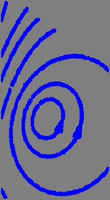
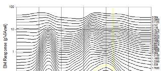
19 SIGNAL SOURCES DISCRETE CONDUCTOR Current induced in discrete conductors termed Vortex currents Commonly modelled using a rectangular thin plate Main anomaly is normally not over centre of conductor
20 SIGNAL SOURCES DISCRETE CONDUCTOR Depth de EM Amplitud VTE Easting
21 SIGNAL SOURCES DISCRETE CONDUCTOR Depth de EM Amplitud VTE Easting

22 SIGNAL SOURCES DISCRETE CONDUCTOR Depth de EM Amplitud VTE Easting
23 SIGNAL SOURCES DISCRETE CONDUCTOR Depth de EM Amplitud VTE Easting


24 SIGNAL SOURCES DISCRETE CONDUCTOR Depth de EM Amplitud VTE Easting

25 SIGNAL SOURCES DISCRETE CONDUCTOR Depth de EM Amplitud VTE Easting
26 SIGNAL SOURCES DISCRETE CONDUCTORS Currents are induced on the surface of the conductor and collapse in to the centre with time Rate of collapse inwards and current decay slow with increasing conductivity For extremely conductive bodies the current decay is so slow that the signal is below noise levels for coils sensor. Several systems offer a B field response Chan nging Magne etic field Magnetic field
27 SIGNAL SOURCES DISCRETE CONDUCTORS Currents are induced on the surface of the conductor and collapse in to the centre with time Rate of collapse inwards and current decay slow with increasing conductivity For extremely conductive bodies the current decay is so slow that the signal is below noise levels for coils sensor. Several systems offer a B field response Chan nging Magne etic field Magnetic field Early, Mid, Late, times or channels


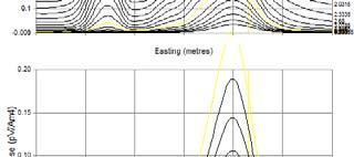
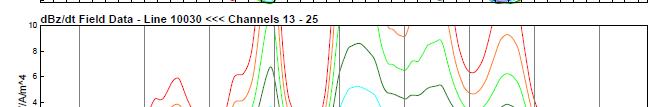
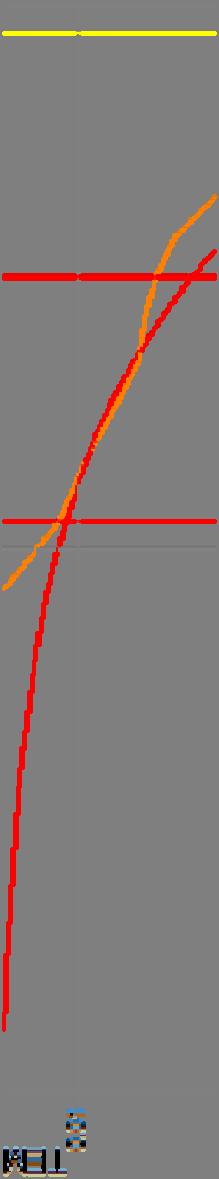
28 SIGNAL SOURCES DISCRETE CONDUCTOR Current in conductive ores are slow decaying and are most visible after the host response from weakly conductive host dies away
29 SIGNAL SOURCES DISCRETE CONDUCTOR Current in conductive ores are slow decaying and are most visible after the host response from weakly conductive host dies away Ch 16
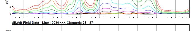
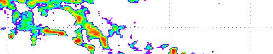
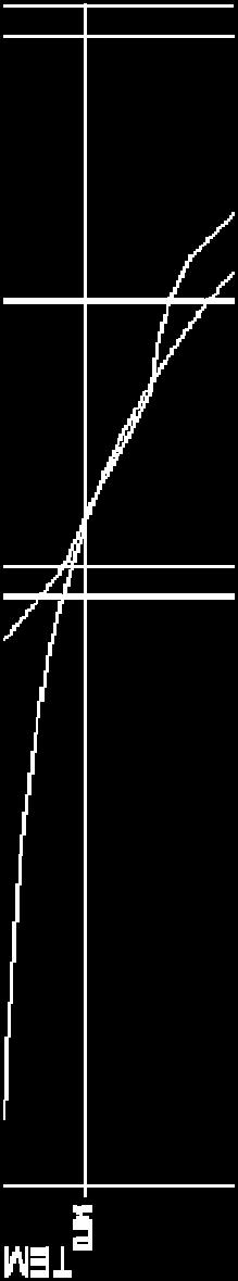
30 SIGNAL SOURCES DISCRETE CONDUCTOR Current in conductive ores are slow decaying and are most visible after the host response from weakly conductive host dies away Ch 25
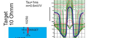
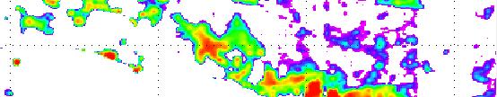
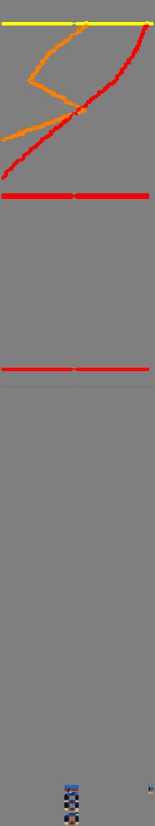
31 SIGNAL SOURCES DISCRETE CONDUCTOR Current in conductive ores are slow decaying and are most visible after the host response from weakly conductive host dies away Ch 35


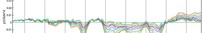
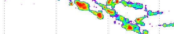
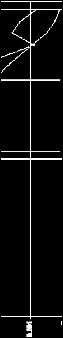
32 SIGNAL SOURCES DISCRETE CONDUCTOR 200m 100m Ch 45
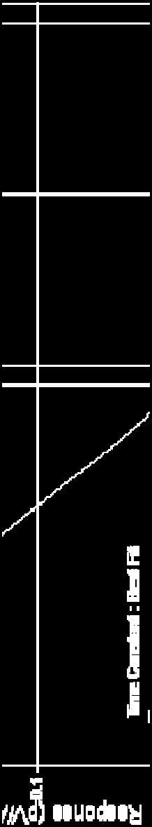
33 SIGNAL SOURCES DISCRETE CONDUCTOR TIME CONSTANT A discrete conductors time constant is a measure of the rate of decay of the induced currents For thin plate is mostly function of conductivity, thickness and dip extent Can be useful for influencing first pass follow up priority W t L S = t (ms) ( ) S(Siemens)W(km) ( ) ( ) Parameters of current vortex L: strike length or largest dimension unimportant W: intermediate dimension, measureofinteraction distance between forward and return currents in target t: thickness S: conductance


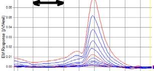
34 SIGNAL SOURCES DISCRETE CONDUCTOR HIGHLY CONDUCTIVE TARGETS YOU WILL NOT DETECT EVERYTHING The Base frequency effects the anomaly amplitude of conductive bodies Time constant are underestimated in AEM data Targets g with high time constant may remain undetected with AEM systems On time measurements help Fortunately most ore bodies have some parts that aren t highly conductive t Frequency of AEM Systems
35 + SIGNAL SOURCES DISCRETE CONDUCTOR HIGHLY CONDUCTIVE TARGETS Airborne EM frequency Airborne EM measuring time t AEM System Frequencies


36 SIGNAL SOURCES DISCRETE CONDUCTOR HIGHLY CONDUCTIVE TARGETS Early times AEM System Ground Coil Ground Fluxgate db/dt db/dt B field Example of suppression of conductor with high time constant AEM System B field calculation undetected Latest times undetected dominates all decay Detected in late times
37 EM SURVEYING SIGNAL SOURCES Our transmitter signal fields (electric and magnetic) interact with the earth in a number of ways some of which we want and some of which we don t: WHAT WE WANT 1. Galvanic Currents: Inductive response from the ground (mapping, groundwater ) 2. Vortex Currents: Inductive response from discrete conductors (for Ni/Cu/Fe ore targets) WHAT WE DON T WANT 1. Ground polarisation effects 2. Superparamagentic effects 3. Noise (Spherics, Powerlines)
38 SIGNAL SYSTEMS SOURCES IMPROVEMENT Dipole Moment Noise Levels Dipole moment (NIA) Tx dbz/dt (pv/a*m^4) Year Year
39 EM SURVEYING SIGNAL SOURCES Our transmitter signal fields (electric and magnetic) interact with the earth in a number of ways some of which we want and some of which we don t: WHAT WE WANT 1. Galvanic Currents: Inductive response from the ground (mapping, groundwater ) 2. Vortex Currents: Inductive response from discrete conductors (for Ni/Cu/Fe ore targets) WHAT WE DON T WANT 1. Ground polarisation effects 2. Superparamagentic effects 3. Noise (Spherics, Powerlines)
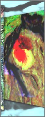
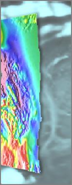
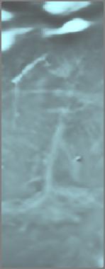
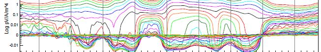
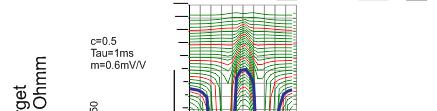
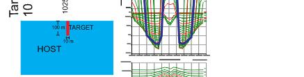
40 EM SURVEYING GROUND POLARISATION Be afraid... Frequency dependent conductivity variations and IP anomalies Caused by the strong electric fields (ie: near surface) from the transmitter loop Electric fields charge up the ground like a capacitor. Like capacitors the ground then discharges In I reality a very complex process Same parameters as measures by IP surveys Causes are most commonly clays, graphitic units, faults, and (uncommonly) disseminated sulphides Complexanomaliesfromeven even simplegeometries. Cannot be intuitively interpreted. Easily identified as negative anomalies but these may not be present or may be offset from source. Very y difficult to model using any software. Particularly dominating of signal in resistive areas.

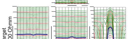


41 EM SURVEYING GROUND POLARISATION Increasing Conductivity Host 500m Incre easing Con nductivity of Chargeable bod dy
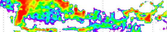
42 EM SURVEYING GROUND POLARISATION 5km
43 EM SURVEYING GROUND POLARISATION 5km

44 EM SURVEYING GROUND POLARISATION 5km

45 EM SURVEYING GROUND POLARISATION
46 EM SURVEYING SIGNAL SOURCES Our transmitter signal fields (electric and magnetic) interact with the earth in a number of ways some of which we want and some of which we don t: WHAT WE WANT 1. Galvanic Currents: Inductive response from the ground (mapping, groundwater ) 2. Vortex Currents: Inductive response from discrete conductors (for Ni/Cu/Fe ore targets) WHAT WE DON T WANT 1. Ground polarisation effects 2. Superparamagentic effects 3. Noise (Spherics, Powerlines)
47 aka. SPM or Magnetic Viscosity EM SURVEYING SUPERPARAMAGNETISM Magnetic state of very fine grained iron oxides. Normally they are what we commonly call non magnetic. Detectable by systems with very high signal and low noise (VTEM, Helitem, Spectem) Caused by the transmitters strong magnetic field briefly aligning gthe magnetic particles creating a secondary field which then decays when magnetic field is turned off. Key difference between decays is the decay rate ( Power Law vs Exponential decay) No applied field With applied field + = Strong Magnetic field
48 EM SURVEYING SUPERPARAMAGNETISM Flying height Soil measure Late time AEM d ment ata Flying Soil height Late tim measurement e AEM data AEM Anomaly due to SPM anomaly AEM Anomaly due to low flying height over ground with moderate SPM


49 BAD NEWS Anomalies often have similar sizes and shapes as orebody signatures Difficult to identify decay type in AEM data EM SURVEYING SUPERPARAMAGNETISM Real conductor 100m deep SPM at surface


50 BAD NEWS Anomalies often have similar sizes and shapes as orebody signatures EM SURVEYING SUPERPARAMAGNETISM Difficult to identify decay type in AEM data Measured decay (note noise) Log dbdt Power law Decay ( 1 gradient) Exponential curve Sample Sensor Ground Coil Sensor Log decay time
 l) EM SURVEYING SUPERPARAMAGNETISM Data Acquisition Unit Sample Sensor Field Sensor")
51 BAD NEWS Anomalies often have similar sizes and shapes as orebody signatures Difficult to identify decay type in AEM data (high base frequency) GOOD NEWS Easy to confirm with ground EM measurements Can be normally quickly and cheaply confirmed with soil measurements (unless deep source such as palaeochannel) l) EM SURVEYING SUPERPARAMAGNETISM Data Acquisition Unit Sample Sensor Field Sensor Core Probe Sensor
52 ACKNOWLEGEMENTS Ken Witherly (Condor Consulting) Jim Macnae (RMIT) Andrew Duncan (EMIT) Jean Legault (Geotech) + Many people who kindly paste info on the net!
Here the goal is to find the location of the ore body, and then evaluate its size and depth.
 Geophysics 223 March 2009 D3 : Ground EM surveys over 2-D resistivity models D3.1 Tilt angle measurements In D2 we discussed approaches for mapping terrain conductivity. This is appropriate for many hydrogeology
Sferic signals for lightning sourced electromagnetic surveys
 Sferic signals for lightning sourced electromagnetic surveys Lachlan Hennessy* RMIT University hennessylachlan@gmail.com James Macnae RMIT University *presenting author SUMMARY Lightning strikes generate
Geology 228/378 Environmental Geophysics Lecture 10. Electromagnetic Methods (EM) I And frequency EM (FEM)
 I And frequency EM (FEM)") Geology 228/378 Environmental Geophysics Lecture 10 Electromagnetic Methods (EM) I And frequency EM (FEM) Lecture Outline Introduction Principles Systems and Methods Case Histories Introduction Many EM
Geology 228/378 Environmental Geophysics Lecture 10 Electromagnetic Methods (EM) I And frequency EM (FEM) Lecture Outline Introduction Principles Systems and Methods Case Histories Introduction Many EM
HELICOPTER-BORNE GEOPHYSICAL SURVEY SYSTEMS
 HELICOPTER-BORNE GEOPHYSICAL SURVEY SYSTEMS APPLICATIONS: base & precious metals exploration diamondiferous kimberlite exploration geological mapping mapping of fault zones for engineering and mining applications
Electromagnetic Induction
 Electromagnetic Induction Recap the motivation for using geophysics We have problems to solve Slide 1 Finding resources Hydrocarbons Minerals Ground Water Geothermal Energy SEG Distinguished Lecture slide
Locating good conductors by using the B-field integrated from partial db/dt waveforms of timedomain
 Locating good conductors by using the integrated from partial waveforms of timedomain EM systems Haoping Huang, Geo-EM, LLC Summary An approach for computing the from time-domain data measured by an induction
7. Consider the following common offset gather collected with GPR.
 Questions: GPR 1. Which of the following statements is incorrect when considering skin depth in GPR a. Skin depth is the distance at which the signal amplitude has decreased by a factor of 1/e b. Skin
Detection of Pipelines using Sub-Audio Magnetics (SAM)
") Gap Geophysics Australia Pty Ltd. Detection of Pipelines using Sub-Audio Magnetics is a patented technique developed by Gap Geophysics. The technique uses a fast sampling magnetometer to monitor magnetic
Gap Geophysics Australia Pty Ltd. Detection of Pipelines using Sub-Audio Magnetics is a patented technique developed by Gap Geophysics. The technique uses a fast sampling magnetometer to monitor magnetic
Stratagem EH4 Geometrics, Inc.
 Stratagem EH4 Geometrics, Inc. Stratagem EH4 Hybrid-Source Magnetotellurics Frequency range of 10 Hz to 90k Hz Approx. depth of investigation from 5m to 1km Portable with rapid setup and teardown Full
Development of a TDEM Data Acquisition System Based on a SQUID Magnetometer for Mineral Exploration
 Development of a TDEM Data Acquisition System Based on a SQUID Magnetometer for Mineral Exploration Eiichi ARAI Toshihiko HAYASHI Tatsuoki NAGAISHI and Hajime OHTA Metals Exploration Group, Japan Oil,
Geology 228 Applied Geophysics Lecture 10. Electromagnetic Methods (EM) (Reynolds, Ch. 10, 11)
 (Reynolds, Ch. 10, 11)") Geology 228 Applied Geophysics Lecture 10 Electromagnetic Methods (EM) (Reynolds, Ch. 10, 11) Lecture Outline Introduction Principles Systems and Methods (FDEM & TDEM) Case Histories APPLICATIONS 1. Mineral
Geology 228 Applied Geophysics Lecture 10 Electromagnetic Methods (EM) (Reynolds, Ch. 10, 11) Lecture Outline Introduction Principles Systems and Methods (FDEM & TDEM) Case Histories APPLICATIONS 1. Mineral
Old & New? INTRODUCTION. The Best Proximal Geophysical Detector Ever!
 Measuring Soil Conductivity with Geonics Limited Electromagnetic Geophysical Instrumentation INTRODUCTION This presentation will briefly discuss the principles of operation and the practical applications
On the Origin of the HTEM Species
 Advances in Airborne Geophysics 1. Xstrata Zinc Canada, Laval, Québec Paper 21 On the Origin of the HTEM Species Allard, M. [1] ABSTRACT By the year 2, the airborne EM world was mainly dominated by two
LOGISTICS AND PROCESSING REPORT GEOTEM Airborne Electromagnetic and Magnetic Survey RENABIE WAWA, ONTARIO. Project No
 Fugro Airborne Surveys LOGISTICS AND PROCESSING REPORT GEOTEM Airborne Electromagnetic and Magnetic Survey RENABIE WAWA, ONTARIO Project No. 13416 Conquest Resources Limited Fugro Airborne Surveys LOGISTICS
In this lecture. Electromagnetism. Electromagnetism. Oersted s Experiment. Electricity & magnetism are different aspects of the same basic phenomenon:
 In this lecture Electromagnetism Electromagnetic Effect Electromagnets Electromechanical Devices Transformers Electromagnetic Effect Electricity & magnetism are different aspects of the same basic phenomenon:
Amplitude balancing for AVO analysis
 Stanford Exploration Project, Report 80, May 15, 2001, pages 1 356 Amplitude balancing for AVO analysis Arnaud Berlioux and David Lumley 1 ABSTRACT Source and receiver amplitude variations can distort
PHYS 1442 Section 004 Lecture #15
 PHYS 1442 Section 004 Lecture #15 Monday March 17, 2014 Dr. Andrew Brandt Chapter 21 Generator Transformer Inductance 3/17/2014 1 PHYS 1442-004, Dr. Andrew Brandt Announcements HW8 on Ch 21-22 will be
THE FEASIBILITY OF THE AIRBORNE FLUXGATE MAGNETOMETER AS AN EXPLORATION TOOL RESULTS FROM THREE DIMENSIONAL NUMERICAL MODELLING
 THE FEASIBILITY OF THE AIRBORNE FLUXGATE MAGNETOMETER AS AN EXPLORATION TOOL RESULTS FROM THREE DIMENSIONAL NUMERICAL MODELLING John Joseph CRC LEME, School of Earth and Environmental Sciences, University
TECHNICAL NOTE EXTREMELY LOW FREQUENCY (ELF) EM SYSTEM
 EM SYSTEM") TECHNICAL NOTE 2012-01 EXTREMELY LOW FREQUENCY (ELF) EM SYSTEM Dave Hildes, Ph.D, P. Geol Aurora Geoscicences Ltd. 34A Laberge Road, Whitehorse, YT, Y1A 5Y9 techniques such as MT / CSAMT / large-loop TEM.
TECHNICAL NOTE 2012-01 EXTREMELY LOW FREQUENCY (ELF) EM SYSTEM Dave Hildes, Ph.D, P. Geol Aurora Geoscicences Ltd. 34A Laberge Road, Whitehorse, YT, Y1A 5Y9 techniques such as MT / CSAMT / large-loop TEM.
Statement of Qualifications
 Revised January 29, 2011 ClearView Geophysics Inc. 12 Twisted Oak Street Brampton, ON L6R 1T1 Canada Phone: (905) 458-1883 Fax: (905) 792-1884 general@geophysics.ca www.geophysics.ca 1 1. Introduction
Exercise 10. Transformers EXERCISE OBJECTIVE DISCUSSION OUTLINE DISCUSSION. Introduction to transformers
 Exercise 10 Transformers EXERCISE OBJECTIVE When you have completed this exercise, you will be familiar with the basic operating principles of transformers, as well as with the different ratios of transformers:
REPORTONTHE ELECTROMAGNETIC SURVEY LV- PYCU- DEER LAKE AREA, LITTLE FORT, FOR BARRIER REEF RESOURCES LTD. (N. P. L. ) AND. MARION A. GOUDIE, B.Sc.
 AND. MARION A. GOUDIE, B.Sc.") w.a..s. NO....... MAP... vo V REPORTONTHE ELECTROMAGNETIC SURVEY LV- PYCU- DEER LAKE AREA, LITTLE FORT, KAMLOOPS MINING DIVISION, B. C. FOR BARRIER REEF RESOURCES LTD. (N. P. L. ) BY PHILIP G. HALLOF,
w.a..s. NO....... MAP... vo V REPORTONTHE ELECTROMAGNETIC SURVEY LV- PYCU- DEER LAKE AREA, LITTLE FORT, KAMLOOPS MINING DIVISION, B. C. FOR BARRIER REEF RESOURCES LTD. (N. P. L. ) BY PHILIP G. HALLOF,
Chapter 25. Electromagnetic Waves
 Chapter 25 Electromagnetic Waves EXAM # 3 Nov. 20-21 Chapter 23 Chapter 25 Powerpoint Nov. 4 Problems from previous exams Physics in Perspective (pg. 836 837) Chapter 25 Electromagnetic Waves Units of
Basics of electrical transformer
 Visit: https://engineeringbasic.com Complete basics and theory of Electrical Transformer Electrical Transformer is the most used electrical machine in power system. Both in the power transmission and distribution
4.4 The transient electromagnetic method (TEM)
") 4.4 The transient electromagnetic method (TEM) 4.4 The transient electromagnetic method (TEM) 4.4.1 Basic principles and measuring techniques in TEM By the transient electromagnetic method, TEM, the electrical
4.4 The transient electromagnetic method (TEM) 4.4 The transient electromagnetic method (TEM) 4.4.1 Basic principles and measuring techniques in TEM By the transient electromagnetic method, TEM, the electrical
A COMPARISON OF ELECTRODE ARRAYS IN IP SURVEYING
 A COMPARISON OF ELECTRODE ARRAYS IN IP SURVEYING John S. Sumner Professor of Geophysics Laboratory of Geophysics and College of Mines University of Arizona Tucson, Arizona This paper is to be presented
Electrical Resistivity Imaging
 Approved for Public Release; Distribution Unlimited Electrical Resistivity Imaging David Hull US Army Research Lab hull@arl.army.mil 17 Jun 2009 ARL Workshop on Personnel, Vehicle, and Tunnel Detection
In an unmagnetized piece of iron, the atoms are arranged in domains. In each domain the atoms are aligned, but the domains themselves are random.
 4/7 Properties of the Magnetic Force 1. Perpendicular to the field and velocity. 2. If the velocity and field are parallel, the force is zero. 3. Roughly (field and vel perp), the force is the product
GEOMETRICS technical report
 GEOMETRICS technical report MA-TR 15 A GUIDE TO PASSIVE MAGNETIC COMPENSATION OF AIRCRAFT A fixed installation of a total field magnetometer sensor on an aircraft is much more desirable than the towed
Kombolgie VTEM AEM Survey: Inversion Report
 Kombolgie VTEM AEM Survey: Inversion Report Geoscience Australia GeoCat 72582 by R.C. Brodie and M.T. Costelloe Department of Resources, Energy and Tourism Minister for Resources and Energy: The Hon. Martin
I p = V s = N s I s V p N p
 UNIT G485 Module 1 5.1.3 Electromagnetism 11 For an IDEAL transformer : electrical power input = electrical power output to the primary coil from the secondary coil Primary current x primary voltage =
Automated anomaly picking from broadband electromagnetic data in an unexploded ordnance (UXO) survey
 survey") GEOPHYSICS, VOL. 68, NO. 6 (NOVEMBER-DECEMBER 2003); P. 1870 1876, 10 FIGS., 1 TABLE. 10.1190/1.1635039 Automated anomaly picking from broadband electromagnetic data in an unexploded ordnance (UXO) survey
GEOPHYSICS, VOL. 68, NO. 6 (NOVEMBER-DECEMBER 2003); P. 1870 1876, 10 FIGS., 1 TABLE. 10.1190/1.1635039 Automated anomaly picking from broadband electromagnetic data in an unexploded ordnance (UXO) survey
Introduction to induced polarization surveying
 Introduction to induced polarization surveying Descriptive outline This module provides background about chargeability, and induced polarization surveying. There are no details about interpretation, inversion,
Presented by: Mike Catalano GEONICS LIMITED
 What s In The Ground: A Non-Invasive Soil Mapping Tool! Presented by: Mike Catalano GEONICS LIMITED INTRODUCTION Measuring Soil Conductivity with Geonics Limited Electromagnetic Geophysical Instrumentation
Geophysical Survey Rock Hill Bleachery TBA Site Rock Hill, South Carolina EP-W EPA, START 3, Region 4 TABLE OF CONTENTS Section Page Signature
 Geophysical Survey Rock Hill Bleachery TBA Site Rock Hill, South Carolina EP-W-05-054 EPA, START 3, Region 4 Prepared for: Tetra Tech EM, Inc. October 12, 2012 Geophysical Survey Rock Hill Bleachery TBA
BUREAU OF MINERAL RESOURCES, GEOLOGY AND GEOPHYSICS
 DEPARTMENT OF MINERALS AND ENERGY BUREAU OF MINERAL RESOURCES, GEOLOGY AND GEOPHYSICS 0 14130 RECORD 1974/126 THE DUAL LOOP CONFIGURATION OF THE TRANSIENT ELECTROMAGNETIC METHOD by BRIAN R. SPIES The,ikfärmation
Total B Field Technologies
 Gap Geophysics Australia Sub-Audio Magnetics () Total B Field Technologies Malcolm Cattach Director Gap Discovery Geophysics Chief Geophysicist Gap Geo Group CEO Gap Geophysics Australia CEO Gap GeoPak
Technical Note TN-30 WHY DOESN'T GEONICS LIMITED BUILD A MULTI-FREQUENCY EM31 OR EM38? J.D. McNeill
 Tel: (905) 670-9580 Fax: (905) 670-9204 GEONICS LIMITED E-mail:geonics@geonics.com 1745 Meyerside Dr. Unit 8 Mississauaga, Ontario Canada L5T 1C6 URL:http://www.geonics.com Technical Note TN-30 WHY DOESN'T
Using representative synthetic data to analyze effects of filters when processing full waveform airborne TEM data
 Using representative synthetic data to analyze effects of filters when processing full waveform airborne TEM data 1. New Resolution Geophysics, South Africa Combrinck, M. [1] OUTLINE Airborne time domain
TABLETOP MODELS FOR ELECTRICAL AND ELECTROMAGNETIC GEOPHYSICS
 TABLETOP MODELS FOR ELECTRICAL AND ELECTROMAGNETIC GEOPHYSICS Charles T. Young Department of Geological Engineering and Sciences, Michigan Technological University, Houghton, MI 49931, (906) 487-2072,
Ground Penetrating Radar
 Ground Penetrating Radar Begin a new section: Electromagnetics First EM survey: GPR (Ground Penetrating Radar) Physical Property: Dielectric constant Electrical Permittivity EOSC 350 06 Slide Di-electric
INVERSION OF EM DATA TO RECOVER 1-D CONDUCTIVITY AND A GEOMETRIC SURVEY PARAMETER. Sean Eugene Walker
 INVERSION OF EM DATA TO RECOVER 1-D CONDUCTIVITY AND A GEOMETRIC SURVEY PARAMETER By Sean Eugene Walker B. Sc. (Honours), Geology & Physics, McMaster University, 1996 a thesis submitted in partial fulfillment
Characterization of noise in airborne transient electromagnetic data using Benford s law
 Characterization of noise in airborne transient electromagnetic data using Benford s law Dikun Yang, Department of Earth, Ocean and Atmospheric Sciences, University of British Columbia SUMMARY Given any
Slide 1. Slide 2. Slide 3. Outline
 Slide 1 Exploration 07 plus 5: A half-decade of mineral exploration developments Ten years of passive airborne EM development for mineral exploration By Jean M. Legault and Paolo Berardelli Geotech Ltd.,
Department of Communications, Marine and Natural Resources
 THE NORANDA/ BILLITON AIRBORNE TEM AND MAGNETIC SURVEY (1997) OVER THE TULLAMORE AREA June 2002 Department of Communications, Marine and Natural Resources Department of Communications, Marine and Natural
Joint MT/CSEM Anisotropic Inversion Olympic Dam
 Joint MT/CSEM Anisotropic Inversion Olympic Dam T.J. Ritchie* P.A. Rowston* Practical 1 Day Workshop Geophysical Inversion for Mineral Explorers * Geophysical Resources and Services Pty. Ltd. Brisbane
Chapter 21. Alternating Current Circuits and Electromagnetic Waves
 Chapter 21 Alternating Current Circuits and Electromagnetic Waves AC Circuit An AC circuit consists of a combination of circuit elements and an AC generator or source The output of an AC generator is sinusoidal
PHYS 1441 Section 001 Lecture #22 Wednesday, Nov. 29, 2017
 PHYS 1441 Section 001 Lecture #22 Chapter 29:EM Induction & Faraday s Law Transformer Electric Field Due to Changing Magnetic Flux Chapter 30: Inductance Mutual and Self Inductance Energy Stored in Magnetic
GCM mapping Vildbjerg - HydroGeophysics Group - Aarhus University
 GCM mapping Vildbjerg - HydroGeophysics Group - Aarhus University GCM mapping Vildbjerg Report number 06-06-2017, June 2017 Indholdsfortegnelse 1. Project information... 2 2. DUALEM-421s... 3 2.1 Setup
Brown University Department of Physics. Physics 6 Spring 2006 A SIMPLE FLUXGATE MAGNETOMETER
 Brown University Department of Physics Physics 6 Spring 2006 1 Introduction A SIMPLE FLUXGATE MAGNETOMETER A simple fluxgate magnetometer can be constructed out available equipment in the lab. It can easily
PHYS 1444 Section 003 Lecture #19
 PHYS 1444 Section 003 Lecture #19 Monday, Nov. 14, 2005 Electric Generators DC Generator Eddy Currents Transformer Mutual Inductance Today s homework is homework #10, due noon, next Tuesday!! 1 Announcements
Magnetism can produce electric current can. produce magnetism Electromagnetic Induction
 Magnetism can produce electric current, and electric current can produce magnetism. In 1831, two physicists, Michael Faraday in England and Joseph Henry in the United States, independently discovered that
3D TEM-IP inversion workflow for galvanic source TEM data
 The University of British Columbia Geophysical Inversion Facility 3D TEM-IP inversion workflow for galvanic source TEM data Seogi Kang and Douglas W. Oldenburg IP workshop 2016 6 th June 2016 gif.eos.ubc.ca
11. AC-resistances of capacitor and inductors: Reactances.
 11. AC-resistances of capacitor and inductors: Reactances. Purpose: To study the behavior of the AC voltage signals across elements in a simple series connection of a resistor with an inductor and with
TULLY TOWNSHIP PROVINCE OF ONTARIO
 S 42A14S68152 63.2756 TOLLY 010 TEXMONT MINES LIMITED ELECTROMAGNETIC AND MAGNETOMETRIC SURVEYS TULLY TOWNSHIP PORCUPINE MINING DIVISION PROVINCE OF ONTARIO BY: C.F. DESSON March 1970 -3 - PROPERTY CLAIM
Technical Note TN-31 APPLICATION OF DIPOLE-DIPOLE ELECTROMAGNETIC SYSTEMS FOR GEOLOGICAL DEPTH SOUNDING. Introduction
 Technical Note TN-31 APPLICATION OF DIPOLE-DIPOLE ELECTROMAGNETIC SYSTEMS FOR GEOLOGICAL DEPTH SOUNDING Introduction In Geonics Limited Technical Note TN-30 Why Doesn t Geonics Limited Build a Multi- Frequency
Advanced Utility Locating Technologies (R01B)
") Advanced Utility Locating Technologies (R01B) Jacob Sheehan Senior Geophysicist Olson Engineering Phil Sirles Principal Geophysicist Olson Engineering Introduction: Utility Bundle Overview SHRP2 Strategic
Advanced Utility Locating Technologies (R01B) Jacob Sheehan Senior Geophysicist Olson Engineering Phil Sirles Principal Geophysicist Olson Engineering Introduction: Utility Bundle Overview SHRP2 Strategic
SIMULATION OF GPR SCENARIOS USING FDTD
 SIMULATION OF GPR SCENARIOS USING FDTD 1 GAMIL ALSHARAHI, 2 ABDELLAH DRIOUACH, 3 AHMED FAIZE 1,2 Department of physic, Abdelmalek Essaâdi University, Faculty of sciences, Morocco 3 Department of physic,
We 21P1 10 Spectral Time Domain IP - Factors Affecting Data Information Content and Applicability to Geological Characterization
 We 21P1 10 Spectral Time Domain IP - Factors Affecting Data Information Content and Applicability to Geological Characterization A. Rezvani* (Lund University), T. Dahlin (Lund University), P.I. Olsson
General Physics (PHY 2140)
") General Physics (PHY 2140) Lecture 11 Electricity and Magnetism AC circuits and EM waves Resonance in a Series RLC circuit Transformers Maxwell, Hertz and EM waves Electromagnetic Waves 6/18/2007 http://www.physics.wayne.edu/~alan/2140website/main.htm
General Physics (PHY 2140) Lecture 11 Electricity and Magnetism AC circuits and EM waves Resonance in a Series RLC circuit Transformers Maxwell, Hertz and EM waves Electromagnetic Waves 6/18/2007 http://www.physics.wayne.edu/~alan/2140website/main.htm
Electromagnetic Induction
 Chapter 16 Electromagnetic Induction In This Chapter: Electromagnetic Induction Faraday s Law Lenz s Law The Transformer Self-Inductance Inductors in Combination Energy of a Current-Carrying Inductor Electromagnetic
Using Representative Synthetic Data to Analyze Effects of Filters When Processing Full Waveform Airborne TEM data
 Paper 8 Using Representative Synthetic Data to Analyze Effects of Filters When Processing Full Waveform Airborne TEM data 1. Tau Geophysical Consultants, Calgary, Canada Combrinck, M. [1] ABSTRACT Airborne
AC Measurement of Magnetic Susceptibility
 AC Measurement of Magnetic Susceptibility Ferromagnetic materials such as iron, cobalt and nickel are made up of microscopic domains in which the magnetization of each domain has a well defined orientation.
WHY YOU NEED A CURRENT BALUN
 HF OPERATORS WHY YOU NEED A CURRENT BALUN by John White VA7JW NSARC HF Operators 1 What is a Balun? A BALUN is a device typically inserted at the feed point of a dipole-like antenna wire dipoles, Yagi
Electrical Engineering / Electromagnetics
 Electrical Engineering / Electromagnetics. Plot voltage versus time and current versus time for the circuit with the following substitutions: A. esistor B. Capacitor C. Inductor t = 0 A/B/C A. I t t B.
ELECTROMAGNETIC COMPATIBILITY HANDBOOK 1. Chapter 8: Cable Modeling
 ELECTROMAGNETIC COMPATIBILITY HANDBOOK 1 Chapter 8: Cable Modeling Related to the topic in section 8.14, sometimes when an RF transmitter is connected to an unbalanced antenna fed against earth ground
#8A RLC Circuits: Free Oscillations
 #8A RL ircuits: Free Oscillations Goals In this lab we investigate the properties of a series RL circuit. Such circuits are interesting, not only for there widespread application in electrical devices,
Analysis of lightning performance of 132KV transmission line by application of surge arresters
 Analysis of lightning performance of 132KV transmission line by application of surge arresters S. Mohajer yami *, A. Shayegani akmal, A.Mohseni, A.Majzoobi High Voltage Institute,Tehran University,Iran
37 Electromagnetic Induction. Magnetism can produce electric current, and electric current can produce magnetism.
 Magnetism can produce electric current, and electric current can produce magnetism. In 1831, two physicists, Michael Faraday in England and Joseph Henry in the United States, independently discovered that
On-time EM measurements: UTEM system developments
 On-time EM measurements: UTEM system developments Sixth Decennial International Conference on Mineral Exploration Workshop 6: Advances in Geophysical Technology Workshop - October 22, 2017 Yves Lamontagne,
PHYS 1444 Section 501 Lecture #20
 PHYS 1444 Section 501 Lecture #0 Monday, Apr. 17, 006 Transformer Generalized Faraday s Law Inductance Mutual Inductance Self Inductance Inductor Energy Stored in the Magnetic Field 1 Announcements Quiz
Identification of UXO by regularized inversion for Surface Magnetic Charges Nicolas Lhomme, Leonard Pasion and Doug W. Oldenburg
 Identification of UXO by regularized inversion for Surface Magnetic Charges Nicolas Lhomme, Leonard Pasion and Doug W. Oldenburg The University of British Columbia, Vancouver, BC, Canada Sky Research Inc.,
1 K Hinds 2012 TRANSFORMERS
 1 K Hinds 2012 TRANSFORMERS A transformer changes electrical energy of a given voltage into electrical energy at a different voltage level. It consists of two coils which are not electrically connected,
Maximizing the Fatigue Crack Response in Surface Eddy Current Inspections of Aircraft Structures
 Maximizing the Fatigue Crack Response in Surface Eddy Current Inspections of Aircraft Structures Catalin Mandache *1, Theodoros Theodoulidis 2 1 Structures, Materials and Manufacturing Laboratory, National
Note on Posted Slides
 Note on Posted Slides These are the slides that I intended to show in class on Tue. Mar. 25, 2014. They contain important ideas and questions from your reading. Due to time constraints, I was probably
A Method of Mapping Resistive or Conductive offshore Targets also an Apparatus for Applying the Method
 A Method of Mapping Resistive or Conductive offshore Targets also an Apparatus for Applying the Method BACKGROUND OF THE INVENTION 1. Field of the Invention The present invention is related to a method
Repeatability study of helicopter-borne electromagnetic data
 GEOPHYSICS, VOL. 71, NO. 6 NOVEMBER-DECEMBER 2006 ; P. G285 G290, 9 FIGS., 2 TABLES. 10.1190/1.2353797 Repeatability study of helicopter-borne electromagnetic data Haoping Huang 1 and Allen Cogbill 2 ABSTRACT
Fastener Hole Crack Detection Using Adjustable Slide Probes
 Fastener Hole Crack Detection Using Adjustable Slide Probes General The guidelines for the adjustable sliding probes are similar to the fixed types, therefore much of the information that is given here
ASHLEY GOLD MINES LIMITED. Induced Polarization Survey Over the. ROW LAKE PROPERTY GRID Katrine Township, Ontario
 PO Box 219 14579 Government Road Larder Lake, Ontario P0K 1L0, Canada Phone (705) 643-1122 Fax (705) 643-2191 ASHLEY GOLD MINES LIMITED Induced Polarization Survey Over the ROW LAKE PROPERTY GRID Katrine
Sw earth Dw Direct wave GRw Ground reflected wave Sw Surface wave
 WAVE PROPAGATION By Marcel H. De Canck, ON5AU Electromagnetic radio waves can propagate in three different ways between the transmitter and the receiver. 1- Ground waves 2- Troposphere waves 3- Sky waves
RESISTIVITY METHODS MT
 Presented at Short Course V on Exploration for Geothermal Resources, organized by UNU-GTP, GDC and KenGen, at Lake Bogoria and Lake Naivasha, Kenya, Oct. 29 Nov. 19, 2010. GEOTHERMAL TRAINING PROGRAMME
Characterizing Subsurface Structures using Very Low Frequency Electromagnetic Radiation - a Modeling Approach
 Characterizing Subsurface Structures using Very Low Frequency Electromagnetic Radiation - a Modeling Approach ERNST D. SCHMITTER University of Applied Sciences Department of Engineering and Computer Sciences
Marine time domain CSEM Growth of and Old/New Technology
 KMS Technologies KJT Enterprises Inc. An EMGS/RXT company Marine time domain CSEM Growth of and Old/New Technology Allegar, N., Strack, K.-M., Mittet, R., Petrov, A., and Thomsen, L. EAGE Rome 2008 Annual
Understanding Seismic Amplitudes
 Understanding Seismic Amplitudes The changing amplitude values that define the seismic trace are typically explained using the convolutional model. This model states that trace amplitudes have three controlling
Today: Finish Chapter 24. Begin Chapter 25 (Magnetic Induction)
") Today: Finish Chapter 24 Begin Chapter 25 (Magnetic Induction) Next Homework posted, due next Fri Dec 11 Electromagnetic Induction Voltage can be induced (created) by a changing magnetic field. C.f. last
Today: Finish Chapter 24 Begin Chapter 25 (Magnetic Induction) Next Homework posted, due next Fri Dec 11 Electromagnetic Induction Voltage can be induced (created) by a changing magnetic field. C.f. last
total j = BA, [1] = j [2] total
![total j = BA, [1] = j [2] total](/thumbs/85/91692343.jpg "total j = BA, [1] = j [2] total") Name: S.N.: Experiment 2 INDUCTANCE AND LR CIRCUITS SECTION: PARTNER: DATE: Objectives Estimate the inductance of the solenoid used for this experiment from the formula for a very long, thin, tightly wound
Name: S.N.: Experiment 2 INDUCTANCE AND LR CIRCUITS SECTION: PARTNER: DATE: Objectives Estimate the inductance of the solenoid used for this experiment from the formula for a very long, thin, tightly wound
Iron Powder Cores for High Q Inductors By: Jim Cox - Micrometals, Inc.
 HOME APPLICATION NOTES Iron Powder Cores for High Q Inductors By: Jim Cox - Micrometals, Inc. SUBJECT: A brief overview will be given of the development of carbonyl iron powders. We will show how the magnetic
Getting Started with Induced Polarization
 Getting Started with Induced Polarization The Induced Polarization How-To Guides walk you through tasks you perform in the Induced Polarization TM (IP) system. The procedures are divided into common procedures
DEVELOPMENT OF VERY LOW FREQUENCY SELF-NULLING PROBE FOR INSPECTION OF THICK LAYERED ALUMINUM STRUCTURES
 DEVELOPMENT OF VERY LOW FREQUENCY SELF-NULLING PROBE FOR INSPECTION OF THICK LAYERED ALUMINUM STRUCTURES Buzz Wincheski and Min Namkung NASA Langley Research Center Hampton, VA 23681 INTRODUCTION Nondestructive
Airborne EM Footprints
 Airborne EM Footprints David Beamish British Geological Survey, Keyworth, Nottingham, NG12 5GG, UK Beamish, D. Airborne EM footprints. Geophysical Prospecting, 2003, 51, 1 12. DOI: 10.1046/j.1365 2478.2003.00353.x
CHAPTER 5 Test B Lsn 5-6 to 5-8 TEST REVIEW
 IB PHYSICS Name: Period: Date: DEVIL PHYSICS BADDEST CLASS ON CAMPUS CHAPTER 5 Test B Lsn 5-6 to 5-8 TEST REVIEW 1. This question is about electric circuits. (a) (b) Define (i) (ii) electromotive force
1. A sinusoidal ac power supply has rms voltage V and supplies rms current I. What is the maximum instantaneous power delivered?
 1. A sinusoidal ac power supply has rms voltage V and supplies rms current I. What is the maximum instantaneous power delivered? A. VI B. VI C. VI D. VI. An alternating current supply of negligible internal
Metal Detector Description
 Metal Detector Description A typical metal detector used for detecting buried coins, gold, or landmines consists of a circular horizontal coil assembly held just above the ground. A pulsed or alternating
Experiment 9: AC circuits
 Experiment 9: AC circuits Nate Saffold nas2173@columbia.edu Office Hour: Mondays, 5:30PM-6:30PM @ Pupin 1216 INTRO TO EXPERIMENTAL PHYS-LAB 1493/1494/2699 Introduction Last week (RC circuit): This week:
Corrosion Steel Inspection under Steel Plate Using Pulsed Eddy Current Testing
 4th International Symposium on NDT in Aerospace 2012 - Poster 4 Corrosion Steel Inspection under Steel Plate Using Pulsed Eddy Current Testing D.M. SUH *, K.S. JANG **, J.E. JANG **, D.H. LEE ** * Raynar
Lab 1. Resonance and Wireless Energy Transfer Physics Enhancement Programme Department of Physics, Hong Kong Baptist University
 Lab 1. Resonance and Wireless Energy Transfer Physics Enhancement Programme Department of Physics, Hong Kong Baptist University 1. OBJECTIVES Introduction to the concept of resonance Observing resonance
Experiment 12: Microwaves
 MASSACHUSETTS INSTITUTE OF TECHNOLOGY Department of Physics 8.02 Spring 2005 OBJECTIVES Experiment 12: Microwaves To observe the polarization and angular dependence of radiation from a microwave generator
GCM mapping Gedved - HydroGeophysics Group - Aarhus University
 GCM mapping Gedved - HydroGeophysics Group - Aarhus University GCM mapping Gedved Report number 23-06-2017, June 2017 1. INDHOLDSFORTEGNELSE 1. Indholdsfortegnelse... 1 2. Project information... 2 3. DUALEM-421s...
Data Acquisition and Processing of a Distributed 3D Induced Polarisation Imaging system
 Data Acquisition and Processing of a Distributed 3D Induced Polarisation Imaging system J Bernard, IRIS Instruments, France IP Workshop W3: IP processing and QC - from amps in the ground to an Inversion
Questions on Electromagnetism
 Questions on Electromagnetism 1. The dynamo torch, Figure 1, is operated by successive squeezes of the handle. These cause a permanent magnet to rotate within a fixed coil of wires, see Figure 2. Harder