Geology 228 Applied Geophysics Lecture 10. Electromagnetic Methods (EM) (Reynolds, Ch. 10, 11)
|
|
|
- Gerard Parks
- 6 years ago
- Views:
Transcription
1 Geology 228 Applied Geophysics Lecture 10 Electromagnetic Methods (EM) (Reynolds, Ch. 10, 11)
2 Lecture Outline Introduction Principles Systems and Methods (FDEM & TDEM) Case Histories
3 APPLICATIONS 1. Mineral exploration - metallic elements are found in highly conductive massive sulfide ore bodies. 2. Groundwater investigations - groundwater contaminants such as salts and acids significantly increase the groundwater conductivity. UConn landfill. 3. Stratigraphy mapping - rock types may have different conductivities. 4. Geothermal energy - geothermal alteration due to hot water increases the conductivity of the host rock. Oil and gas. 5. Permafrost mapping - there is a significant conductivity contrast at the interface between frozen and unfrozen ground. 6. Environmental - locate hazards such as drums and tanks, contaminant plumes. UXO, landmine
4 ADVANTAGES 1. TDEM systems may be used in many different configurations. 2. A pulsed transmitter waveform allows the receiver to measure the electromagnetic response during the transmitter off-time without the presence of the primary field. 3. No direct electrical contact with the ground is required so that surveys can be equally effective in frozen environments. 4. The same basic techniques can be used to investigate the top few meters of ground or to depths over 1000 meters. 5. Generally fast and cost effective for the amount of data generated.
5 Limitations Do not work well for high resistive region. Susceptible to interference from nearby metal pipes, cables, fences, vehicles and induced noise from power lines. EM equipment tends to be somewhat more costly due to its greater complexity. Need more sophisticated interpretation skill. Not effective for very shallow measurements. Fixed depth of investigation depending on frequency used and Tx-Rx separation.
6 Types of EM Systems 1. TDEM vs FDEM Time-domain (TDEM) Measurements as a function of time Frequency-domain (FDEM) Measurements at one or more frequencies 2. Passive vs Active Passive: Uses natural ground signals (e.g., magnetotellurics), sources are lightning, magnetosphere activities, etc. Active: use transmitter to induce ground current Near-field ( ground conductivity meters) Far-field (VLF uses very low frequency signals used to communicate with submarines ).
7 Types of EM Systems Inductive Small loop Most FDEM (EM 31, EM 34, etc.) but some TDEM Most widely used in environmental investigations Large loop (5 m to 100 m loops) Many TDEM systems ( esp. airborne) Mineral exploration, environmental investigations Plane wave (VLF, Magnetotelluric) Mineral exploration, deep geologic structure
 Pole, two small coils, one transmitter")

8 Small Loop Systems FDEM ( frequency domain EM) Pole, two small coils, one transmitter and one receiver, separated by a constant spacing moved along a survey transect. Geonics EM31

9 Small loop systems Two coils( transmitter and receiver) connected by wires that permit several different separations and configurations Geonics EM34
10 Loop configurations HCP (horizontal co-planer) VCP (vertical co-planer) VCA (vertical Coaxial) Others


11 How does EM Induction work? Magnetism Magnetic lines of force ( owing to alignment of atoms, the H-field)

12 EM Theory (1) In 1820, Hans Oersted discovered that a magnetic compass could be deflected from its resting position if a wire carrying electric current were placed near the compass. Magnetic Field Any wire in which an electric current is flowing is surrounded by an invisible force field called a magnetic field. This phenomenon is described as the Ampere s law. H = Idl r 2πr 0 2

13 EM Theory (2) Electromagnetism The term electromagnetism is defined as the production of a magnetic field by current flowing in a conductor. Coiling a current-carrying conductor around a core material that can be easily magnetized, such as iron, can form an electromagnet. The magnetic field will be concentrated in the core. This arrangement is called a solenoid. The more turns we wrap on this core, the stronger the electromagnet and the stronger the magnetic lines of force become.
.")
14 Right hand being used to find the polarity of the magnetic field around a coil of wire (the thumb is pointing towards the North pole) when you know the direction of the current around the coil (the fingers are wrapping around the coil in the same direction as the current). Notice that all of the lines of force pass through the center of the coil material, regardless of how they extend outside the coil of wire.
15 EM Theory (3) The magnetic field that surrounds a currentcarrying conductor is made up of concentric lines of force. The strength of these circular lines of force gets progressively smaller the further away from the conductor. if a stronger current is made to flow through the conductor, the magnetic lines of force become stronger. the strength of the magnetic field is directly proportional to the current that flows through the conductor. H = Idl r 2πr 2 0
16 EM Theory (4) The term field intensity is used to describe the strength of the magnetic field. We have now seen that if electrical current is flowing in a conductor, there is an associated magnetic field created around the wire. In a similar manner, if we move a wire inside a magnetic field there will be an electrical current that will be generated in the wire. This is described as the Faraday s law.
17 EM Theory (5) Induction Current is produced in a conductor when it is moved through a magnetic field because the magnetic lines of force are applying a force on the free electrons in the conductor and causing them to move. The direction that the induced current flows is determined by the direction of the lines of force and by the direction the wire is moving in the field. If an AC current is fed through a piece of wire, the electromagnetic field that is produced is constantly growing and shrinking due to the constantly changing current in the wire. This growing and shrinking magnetic field can induce electrical current in another wire that is held close to the first wire. The current in the second wire will also be AC and in fact will look very similar to the current flowing in the first wire.

18 If we move a wire in a magnetic field, the movement will create a current in the wire. Essentially, as we cut through the magnetic lines of force, we cause the electrons to move in the wire. The faster we move the wire, the more current we generate. Again, the right hand helps determine which way the current is going to flow. If you hold your hand as is shown in the diagram below, point your index finger in the direction of the magnetic lines of force (N to S...) and your thumb in the direction of the movement of the wire relative to the lines of force, your middle finger will point in the direction of the current.
19 Principles of EM Surveying Generate EM field by passing an AC through a wire coil ( transmitter) EM field propagates above and below ground. If there is conductive material in ground, magnetic component of the EM wave induces eddy currents (AC) in conductor. The eddy currents produce a secondary EM field which is detected by the receiver. The receiver also detects the primary field (the resultant field is a combination of primary and secondary which differs from the primary field in phase and amplitude). After compensating for the primary field (which can be computed from the relative positions and orientations of the coils), both the magnitude and relative phase of the secondary field can be measured. The difference in the resultant field from the primary provides information about the geometry, size and electrical properties of the subsurface conductor.
20 Secondary field can be converted to components in-phase and 90 out of phase with the transmitted field. The out-of-phase (or quadrature-phase ) component, using certain simplifying assumptions, can be converted to a measure of apparent ground conductivity. The in-phase component, while generally not responsive to changes in bulk conductivity, is especially responsive to discrete, highly-conductive bodies such as metal objects. The apparent conductivity measurement is the average conductivity of one or more layers in the ground in the proximity of the instrument, to a depth of investigation dependent on the coil spacing, orientation, operating frequency of the instrument, and the individual conductivity of each ground layer.
21
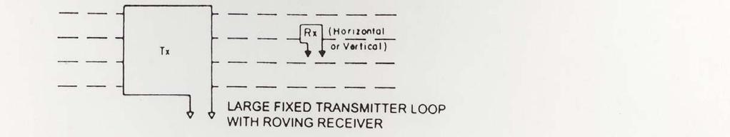
22 General Principles of EM Operation FDEM: Transmitter produces continuous EM field, secondary field is determined by nulling the primary field ( need two coils); TDEM Primary field is applied in pulses ( ms) then switched off and the secondary field measured ( same coil can be transmitter and receiver, more often large coil on ground and move small coil around).
23 Factors influencing subsurface electrical conductivity Mineralogy Clays more conductive (relates to CEC) Moisture content Porosity EC of the subsurface water Stratigraphy Structure Temporal Changes in soil EC due to soil moisture change, water table changes, soils are frozen ( Low EC), soil temperature changes (lowers EC of soil water). Adding or subtracting soluble constituents (contaminants) source strength variations and directions of ground water flow. Presence of NAPLs
24 Relative Response φ Horizontal dipole Vertical dipole z dz z = normalized depth: =depth/(inter-coil spacing); φ= relative contribution to Hs from a thin layer at depth z; For Vertical dipole, max contribution of layer is at.4z, not sensitive to surface conditions.

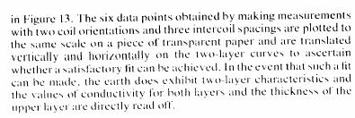
25 Using different spacing and configurations in Modeling
26 Advantages Relative to DC Resistivity Less sensitive to conditions at surface of ground No problems with coupling to ground since it is inductive. Perform simple multilayered earth calcs. Easy and Rapid Measurements On plane and boat
27 Disadvantages relative to DC resistivity Limited dynamic range ( mmhos/m) Low EC: can t readily induce current High EC: EC not linear function of H Setting instrument to zero Ideally needs to suspending in free space Reality set to zero rel. prevailing conditions Limited vertical sounding capability
28 Survey Instruments Frequency-domain Electromagnetic Methods (FDEM)
29 Frequency Domain Theory Measure the frequency response H(ω) and E(ω) Alternating field source In-phase and quadrature Host rock is ignored (assume electromagnetically transparent)
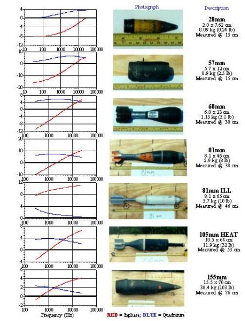
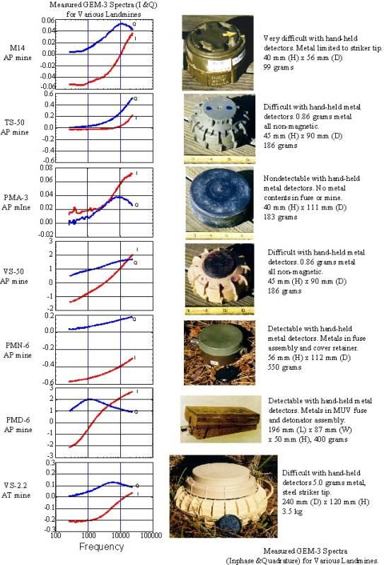
30 Measured Response Conductive and permeable sphere in free space ( ) cosθ ( ) H = H + H H + H s r, r θ, r 0 r, θ θ, θ 0 Radial Source H r,r and H r,θ Transverse Source H θ,r and H θ,θ r = r 0, θ = 0 for the GEM-3 sinθ Figure: Characterization of UXO-Like Targets Using Broadband Electromagnetic Induction Sensor, H. Huang and I.J. Won
31 Response Components m a H X iy n( n 1) P (cos θ ) 2n+ 1 r rr, = ( n+ n) + n+ 2 n 4 π n= 1 ( rr0 ) m a H X iy np 2n+ 1 r 1 r, θ = ( n + n) n+ 2 n 4 π n= 1 ( rr0 ) m a H X iy np 2n+ 1 r θ, r = ( n + n) n+ 2 n 4 π n= 1 ( rr0 ) m H X iy 2n+ 1 r θθ, = ( n + n) n+ 2 4 π n= 1 ( rr0 ) (cos θ ) (cos θ ) 2 n 1 npncosθ cotθpn ( cosθ) n 1 + where P is the nth-order Legendre polynomial n a
32 The Response Function Contains all the EM properties and the size of the sphere X n + iy = n 1 µ r n+ n nµ r I ka + kai ka 2 ( n 1) I ( ka) kai ( ka) ( ) ( ) 1 1 n+ n+ 2 2 ( ) k = i I ka 2 which ωµσ and n+ 12 is the modifed spherical ( ) Besselfunction of thefirst kind at order n + 1 2
33 Graphical Representation a = 0.1m, r = 0.6m σ = 10 6 S/m, µ = 200 Induction number Θ = (σµω) 1/2 a Figures: Characterization of UXO-Like Targets Using Broadband Electromagnetic Induction Sensor, H. Huang and I.J. Won

34 EM survey on move

35 EM 31 GEONICS
36 EM 31 Characteristics Intercoil spacing of 3.7 m. Effective depth of exploration = 6 m (pole horizontal), 3 m (pole vertical) Detect layering by rasing and lower instrument. Procedure: Lay out survey line with a measuring tape, walk to measurement location, turn on transmitter read apparent conductivity ( in millimhos/m)

37 EM 34 GEONICS
38 EM 34 Characteristics Two person instrument Intercoil spacing of 10, 20 and 40M Intercoil spacing is measured electronically, read meter to accurately set spacing.
39 Survey procedure: (1) Lay out survey line with tape (2) Transmitter operator stops at measurement station. (3) The receiver operator moves coil forward and back until his meter indicates correct intercoil spacing. (4) The transmitter operator reads apparent conductivity in millimhos/m. (5) Takes sec per reading. (6) Normally survey in horizontal dipole mode ( coils vertical) which is less subject to coil misalignment. (7) you can also use vertical dipole ( coils horizontal).
40 EM 31 and 34 relation of H to σ Instruments are designed to operate at: Specific fixed frequencies, Fixed inter-coil spacings and at Fixed Hp Given above instrument constraints: σ directly proportional to Hs/Hp Depth of penetration primarily function of instrument configuration

41 The basic GEM-3 Package consists of: a 64-cm diameter sensing head, handle boom, console and display unit, and battery charger. Standard software includes WinGEMv3, Windows-based operation software. The optional 96-cm head, due to its size, must be mounted on a cart. Programmable Operation Bandwidth 30 Hz to 24 khz Frequency domain Single, multiple, or stepping frequencies Maximum sampling rate Approx. 15 Hz at one frequency or 8 Hz at 10 frequencies

42


43 Airborne Surveying GEOTEM T and R separations m


44 The World s Most Advanced HEM System Redefining Helicopter Electromagnetics Reliable, Repeatable, Precise 3D RESISTIVITY Unsurpassed Horizontal and Vertical RESOLUTION RESOLVE your Questions. SOLVE your Exploration Problems RESOLVE -a unique six frequency system with horizontal coplanar coils capable of measuring the EM response at 400Hz, 1500Hz, 6400Hz, 25kHz, 100kHz, and one coaxial coil pair at 3300Hz. Designed for the calculation of 3D earth resitivity models, overburden thickness, layered inversions, EM-derived susceptibility and other advanced products. Horizontal coplanar coil pairs combined with a coaxial coil pair are excellent for interpreting conductors. RESOLVE is fully digital, offering lower noise and real-time signal processing as well as internal calibration coils for automatic phase and gain calibration in the air - out of ground effect - resulting in higher accuracy and reduced drift. RESOLVE offers the exploration professional horizontal and vertical resolution unparalleled in an airborne EM system. Multiple coplanar coils are exceptional for mapping horizontal layers.


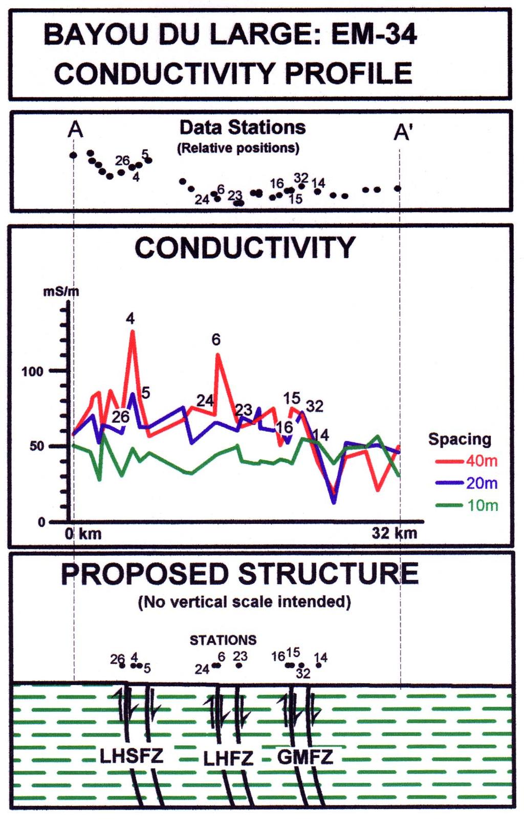
45 Saltwater intrusion along the Baton Rouge Fault (Kuecher, 2004)
46
47 Time-domain Electromagnetic Methods (TDEM)
48 TIME DOMAIN ELECTROMAGNETICS Time-Domain Electromagnetic (TDEM) methods are based on the principle of using electromagnetic induction to generate measurable responses from sub-surface features. When a steady current in a cable loop is terminated a time varying magnetic field is generated. As a result of this magnetic field, eddy currents are induced in underground conductive materials. The decay of the eddy currents in these materials is directly related to their conductive properties, and may be measured by a suitable receiver coil on the surface.

49 Physical Principle of TDEM
50 Maxwell s two curl equations Faraday s law Ampere s law Η Ε = µ t Η = Ε J + ε c t Where, σ : conductivity µ : magnetic permeability ε : permittivity J : conductive current, c J c = σe
51 Η Ε = µ t Η = Ε J + ε c t Η Ε= ( µ ) t = µ ( Η) t E = µ ( σe + ε ) t t E = t σµ µε 2 t E 2
52 E E E E ( ) E E E E t t t t t t t t σµ µε σµ µε σµ µε σµ µε Ε= Ε Ε= Ε = Ε= + 0
53 Similarly, Ε Ε 2 Ε = σµ + µε t t 2 Η Η 2 Η = σµ + µε t t 2 2 2
54 For example, let s think about H-field t H(r, t) = σµ + µε t Where, r = r( x, y, z) 2 2 H(r, ) H(r, ) Do Fourier transform to both side for E(r, t) with respect to t t 2 t 2 H(r, ω) = jσµωh(r, ω) 2 µεω H(r, ω) Diffusion component Wave propagation
55 Diffusion equation (Frequency domain) 2 H(r, ω) jσµωh(r, ω) Inverse Fourier transform Diffusion equation (Time domain) 2 H(r, t) H(r, t) σµ t 2 E(r, t) η H(r, t) σµ t, η : em impedence
56 σ ωµ ωε σ ωµ η σµ η ωε σ j j, ) H(r, ) E(r, 2 + = j t t t ) H(r, ) 0.707(1 ) H(r, ) E(r, 3 2 t t j t t t + ωσµ ησµ ] H,, [ α E t µ σ So:
57 Condition: In order to identify a specific feature, it is necessary that its inherent electrical conductivity contrast significantly with the conductivity of surrounding materials. In most successful TDEM applications, the targets sought possess enhanced conductivities relative to their host material.
58 Penetration of EM wave Skin depth : the amplitude of EM radiation as a Function of of depth (z) relative to its original amplitude A 0 is given by: Az = A0 / e.3679 A0, e = Skin depth (m) is given by δ = 2 ωσµ 503 f σ
 With true 23 bit resolution (at a single gain), system bandwidth of 270 khz, microsecond sampling gates and simultaneous three")
59 The PROTEM receiver enables the selection of either 20 gates per base frequency covering two decades of time, or 30 gates for a three decade range. Protem receiver box (EM 47/57/67) With true 23 bit resolution (at a single gain), system bandwidth of 270 khz, microsecond sampling gates and simultaneous three component (XYZ) measurements.

60 TEM47 TRANSMITTER BASE FREQUENCY: 30, 75, or 285 Hz where powerline frequency is 60 Hz 25, 62.5 or Hz where powerline frequency is 50 Hz TRANSMITTER LOOP: 5 x 5 to 100 Penetration x 100 m single up to turn 100 loop, m or 5 x 5 m 8-turn loop OUTPUT VOLTAGE0 to 9 V, continuously variable

61 TEM57 TRANSMITTER BASE FREQUENCY: 3, 7.5, or 30 Hz where powerline frequency is 60 Hz 2.5, 6.25, or 25 Hz where powerline frequency is 50 Hz Rates below 1 Hz available from PROTEM receiver through reference cable TRANSMITTER LOOP Single turn: any dimension; minimum resistance is 0.7 ohms, up to 300 x 600 m. 8-turn: 5 x 5 or 10 x 10 m Penetration up to 500 m

62 TEM67 TRANSMITTER Base frequency: 0.3, 0.75, 3, 7.5 or 30 Hz where power line frequency is 60 Hz 0.25, 0.625, 2.5 or 25 Hz where power line frequency 50 Hz TRANSMITTER LOOP Up to 2,000 x 2,000 m single turn OUTPUT CURRENT25 Penetration A maximumup to 1000 m
 SENSOR AREA-TURNS PRODUCT 5000 m2 for axial and 1250 m2 for radial sensors (with amplification) SENSOR-PREAMPLIFIER RESONANT FREQUENCY 10")
63 BH43-3 Borehole TDEM Probe The BH43-3 provides three dimensional time domain EM exploration from boreholes, in conjunction with a PROTEM system. SENSOR Three orthogonal coils (one axial and two radial) SENSOR AREA-TURNS PRODUCT 5000 m2 for axial and 1250 m2 for radial sensors (with amplification) SENSOR-PREAMPLIFIER RESONANT FREQUENCY 10 khz for all sensors Logging depth to 2 kilometers

64 GEONICS EM 61 The EM61, one of the newest instruments from GEONICS, is a time-domain metal detector which detects both ferrous and non-ferrous metals.
 and magnetotelluric (MT) surveys.")
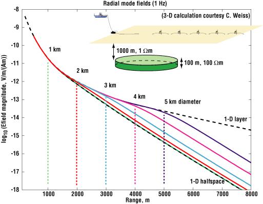
65 Marine EM Illustration of Controlled source EM (CSEM) and magnetotelluric (MT) surveys.
66 Data interpretation
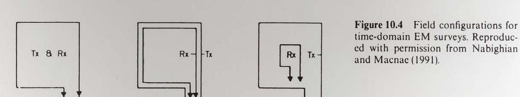
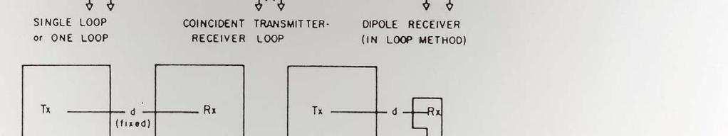
67 TX-RX Configurations
68 Transmitter Current
69
70 Measurement Sample gates
71 Dipole Configuration: TX and RX
72 Induction eddy currents
73 Receiver Output Voltage Curve
74 Output voltage e(t)= output voltage from a single-turn receiver coil of area 1 m 2 k 1 = a constant M = magnetic moment: product of Tx current and area (a-m 2 ) σ = terrain conductivity (siemens/m = S/m = 1/Ωm) t = time (s) Output apparent resistivity k 2 = a constant
75
76 Three typical EM response curves
77 TDEM response corrupted by noise due to Power line
78 Summary EM is capable to get subsurface information from greater depth; EM can reveal material changes other than the mechanic ones (elastic modulus and density); EM is becoming a widely used tool for geoelectrical sounding, on land, in the air and in the ocean.
Geology 228/378 Environmental Geophysics Lecture 10. Electromagnetic Methods (EM) I And frequency EM (FEM)
 I And frequency EM (FEM)") Geology 228/378 Environmental Geophysics Lecture 10 Electromagnetic Methods (EM) I And frequency EM (FEM) Lecture Outline Introduction Principles Systems and Methods Case Histories Introduction Many EM
Geology 228/378 Environmental Geophysics Lecture 10 Electromagnetic Methods (EM) I And frequency EM (FEM) Lecture Outline Introduction Principles Systems and Methods Case Histories Introduction Many EM
Electromagnetic Induction
 Electromagnetic Induction Recap the motivation for using geophysics We have problems to solve Slide 1 Finding resources Hydrocarbons Minerals Ground Water Geothermal Energy SEG Distinguished Lecture slide
Old & New? INTRODUCTION. The Best Proximal Geophysical Detector Ever!
 Measuring Soil Conductivity with Geonics Limited Electromagnetic Geophysical Instrumentation INTRODUCTION This presentation will briefly discuss the principles of operation and the practical applications
Here the goal is to find the location of the ore body, and then evaluate its size and depth.
 Geophysics 223 March 2009 D3 : Ground EM surveys over 2-D resistivity models D3.1 Tilt angle measurements In D2 we discussed approaches for mapping terrain conductivity. This is appropriate for many hydrogeology
Technical Note TN-30 WHY DOESN'T GEONICS LIMITED BUILD A MULTI-FREQUENCY EM31 OR EM38? J.D. McNeill
 Tel: (905) 670-9580 Fax: (905) 670-9204 GEONICS LIMITED E-mail:geonics@geonics.com 1745 Meyerside Dr. Unit 8 Mississauaga, Ontario Canada L5T 1C6 URL:http://www.geonics.com Technical Note TN-30 WHY DOESN'T
HELICOPTER-BORNE GEOPHYSICAL SURVEY SYSTEMS
 HELICOPTER-BORNE GEOPHYSICAL SURVEY SYSTEMS APPLICATIONS: base & precious metals exploration diamondiferous kimberlite exploration geological mapping mapping of fault zones for engineering and mining applications
Detecting metal objects in magnetic environments using a broadband electromagnetic method
 GEOPHYSICS, VOL. 68, NO. 6 (NOVEMBER-DECEMBER 2003); P. 1877 1887, 13 FIGS., 2 TABLES. 10.1190/1.1635040 Detecting metal objects in magnetic environments using a broadband electromagnetic method Haoping
WHAT ARE WE MEASURING?
 WHAT ARE WE MEASURING? ASEG Workshop on Airborne Electromagnetics P th Perth November 7th 2012 P. Mutton, Consulting Geophysicist Southern Geoscience Consultants www.sgc.com.au WHAT ARE WE MEASURING? OUTLINE
Ground Penetrating Radar
 Ground Penetrating Radar Begin a new section: Electromagnetics First EM survey: GPR (Ground Penetrating Radar) Physical Property: Dielectric constant Electrical Permittivity EOSC 350 06 Slide Di-electric
GEONICS LIMITED LEADERS IN ELECTROMAGNETICS GEOPHYSICAL INSTRUMENTATION FOR EXPLORATION & THE ENVIRONMENT
 GEONICS LIMITED LEADERS IN ELECTROMAGNETICS GEOPHYSICAL INSTRUMENTATION FOR EXPLORATION & THE ENVIRONMENT GEONICS LIMITED 1745 Meyerside Drive, Unit 8 Mississauga, Ontario Canada L5T 1C6 Telephone: +1
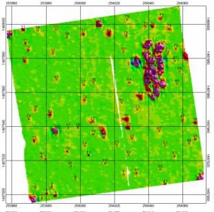
Automated anomaly picking from broadband electromagnetic data in an unexploded ordnance (UXO) survey
 survey") GEOPHYSICS, VOL. 68, NO. 6 (NOVEMBER-DECEMBER 2003); P. 1870 1876, 10 FIGS., 1 TABLE. 10.1190/1.1635039 Automated anomaly picking from broadband electromagnetic data in an unexploded ordnance (UXO) survey
GEOPHYSICS, VOL. 68, NO. 6 (NOVEMBER-DECEMBER 2003); P. 1870 1876, 10 FIGS., 1 TABLE. 10.1190/1.1635039 Automated anomaly picking from broadband electromagnetic data in an unexploded ordnance (UXO) survey
In this lecture. Electromagnetism. Electromagnetism. Oersted s Experiment. Electricity & magnetism are different aspects of the same basic phenomenon:
 In this lecture Electromagnetism Electromagnetic Effect Electromagnets Electromechanical Devices Transformers Electromagnetic Effect Electricity & magnetism are different aspects of the same basic phenomenon:
GEONICS LIMITED LEADERS IN ELECTROMAGNETICS GEOPHYSICAL INSTRUMENTATION FOR EXPLORATION & THE ENVIRONMENT
 GEONICS LIMITED LEADERS IN ELECTROMAGNETICS GEOPHYSICAL INSTRUMENTATION FOR EXPLORATION & THE ENVIRONMENT GEONICS LIMITED 1745 Meyerside Drive, Unit 8 Mississauga, Ontario Canada L5T 1C6 Telephone: +1
7. Consider the following common offset gather collected with GPR.
 Questions: GPR 1. Which of the following statements is incorrect when considering skin depth in GPR a. Skin depth is the distance at which the signal amplitude has decreased by a factor of 1/e b. Skin
Presented by: Mike Catalano GEONICS LIMITED
 What s In The Ground: A Non-Invasive Soil Mapping Tool! Presented by: Mike Catalano GEONICS LIMITED INTRODUCTION Measuring Soil Conductivity with Geonics Limited Electromagnetic Geophysical Instrumentation
GCM mapping Vildbjerg - HydroGeophysics Group - Aarhus University
 GCM mapping Vildbjerg - HydroGeophysics Group - Aarhus University GCM mapping Vildbjerg Report number 06-06-2017, June 2017 Indholdsfortegnelse 1. Project information... 2 2. DUALEM-421s... 3 2.1 Setup
A COMPARISON OF ELECTRODE ARRAYS IN IP SURVEYING
 A COMPARISON OF ELECTRODE ARRAYS IN IP SURVEYING John S. Sumner Professor of Geophysics Laboratory of Geophysics and College of Mines University of Arizona Tucson, Arizona This paper is to be presented
Electromagnetic Induction - A
 Electromagnetic Induction - A APPARATUS 1. Two 225-turn coils 2. Table Galvanometer 3. Rheostat 4. Iron and aluminum rods 5. Large circular loop mounted on board 6. AC ammeter 7. Variac 8. Search coil
CHAPTER 5 CONCEPTS OF ALTERNATING CURRENT
 CHAPTER 5 CONCEPTS OF ALTERNATING CURRENT INTRODUCTION Thus far this text has dealt with direct current (DC); that is, current that does not change direction. However, a coil rotating in a magnetic field
Technical Note TN-31 APPLICATION OF DIPOLE-DIPOLE ELECTROMAGNETIC SYSTEMS FOR GEOLOGICAL DEPTH SOUNDING. Introduction
 Technical Note TN-31 APPLICATION OF DIPOLE-DIPOLE ELECTROMAGNETIC SYSTEMS FOR GEOLOGICAL DEPTH SOUNDING Introduction In Geonics Limited Technical Note TN-30 Why Doesn t Geonics Limited Build a Multi- Frequency
3. Electromagnetic methods 3.1 Introduction
 3. Electromagnetic methods 3.1 Introduction The electromagnetic techniques have the broadest range of different instrumental systems. They can be classified as either time domain (TEM) of frequency domain
DEEP FLAW DETECTION WITH GIANT MAGNETORESISTIVE (GMR) BASED SELF-NULLING PROBE
 BASED SELF-NULLING PROBE") DEEP FLAW DETECTION WITH GIANT MAGNETORESISTIVE (GMR) BASED SELF-NULLING PROBE Buzz Wincheski and Min Namkung NASA Langley Research Center Hampton, VA 23681 INTRODUCTION The use of giant magnetoresistive
DEEP FLAW DETECTION WITH GIANT MAGNETORESISTIVE (GMR) BASED SELF-NULLING PROBE Buzz Wincheski and Min Namkung NASA Langley Research Center Hampton, VA 23681 INTRODUCTION The use of giant magnetoresistive
Development of a TDEM Data Acquisition System Based on a SQUID Magnetometer for Mineral Exploration
 Development of a TDEM Data Acquisition System Based on a SQUID Magnetometer for Mineral Exploration Eiichi ARAI Toshihiko HAYASHI Tatsuoki NAGAISHI and Hajime OHTA Metals Exploration Group, Japan Oil,
Liquidmetal Electromagnetic Properties & RF Shielding Overview
 Liquidmetal Electromagnetic Properties & RF Shielding Overview Liquidmetal alloy is more transparent to RF signals than many similar materials 1 Introduction H ow a material interacts with radio frequency
Sferic signals for lightning sourced electromagnetic surveys
 Sferic signals for lightning sourced electromagnetic surveys Lachlan Hennessy* RMIT University hennessylachlan@gmail.com James Macnae RMIT University *presenting author SUMMARY Lightning strikes generate
R. W. Erickson. Department of Electrical, Computer, and Energy Engineering University of Colorado, Boulder
 R. W. Erickson Department of Electrical, Computer, and Energy Engineering University of Colorado, Boulder 13.2.3 Leakage inductances + v 1 (t) i 1 (t) Φ l1 Φ M Φ l2 i 2 (t) + v 2 (t) Φ l1 Φ l2 i 1 (t)
CH 1. Large coil. Small coil. red. Function generator GND CH 2. black GND
 Experiment 6 Electromagnetic Induction "Concepts without factual content are empty; sense data without concepts are blind... The understanding cannot see. The senses cannot think. By their union only can
Geophysical Survey Rock Hill Bleachery TBA Site Rock Hill, South Carolina EP-W EPA, START 3, Region 4 TABLE OF CONTENTS Section Page Signature
 Geophysical Survey Rock Hill Bleachery TBA Site Rock Hill, South Carolina EP-W-05-054 EPA, START 3, Region 4 Prepared for: Tetra Tech EM, Inc. October 12, 2012 Geophysical Survey Rock Hill Bleachery TBA
ELECTROMAGNETIC INDUCTION AND ALTERNATING CURRENT (Assignment)
") ELECTROMAGNETIC INDUCTION AND ALTERNATING CURRENT (Assignment) 1. In an A.C. circuit A ; the current leads the voltage by 30 0 and in circuit B, the current lags behind the voltage by 30 0. What is the
ELECTROMAGNETIC INDUCTION AND ALTERNATING CURRENT (Assignment) 1. In an A.C. circuit A ; the current leads the voltage by 30 0 and in circuit B, the current lags behind the voltage by 30 0. What is the
Stratagem EH4 Geometrics, Inc.
 Stratagem EH4 Geometrics, Inc. Stratagem EH4 Hybrid-Source Magnetotellurics Frequency range of 10 Hz to 90k Hz Approx. depth of investigation from 5m to 1km Portable with rapid setup and teardown Full
GCM mapping Gedved - HydroGeophysics Group - Aarhus University
 GCM mapping Gedved - HydroGeophysics Group - Aarhus University GCM mapping Gedved Report number 23-06-2017, June 2017 1. INDHOLDSFORTEGNELSE 1. Indholdsfortegnelse... 1 2. Project information... 2 3. DUALEM-421s...
Antenna Engineering Lecture 3: Basic Antenna Parameters
 Antenna Engineering Lecture 3: Basic Antenna Parameters ELC 405a Fall 2011 Department of Electronics and Communications Engineering Faculty of Engineering Cairo University 2 Outline 1 Radiation Pattern
Detection of Pipelines using Sub-Audio Magnetics (SAM)
") Gap Geophysics Australia Pty Ltd. Detection of Pipelines using Sub-Audio Magnetics is a patented technique developed by Gap Geophysics. The technique uses a fast sampling magnetometer to monitor magnetic
Gap Geophysics Australia Pty Ltd. Detection of Pipelines using Sub-Audio Magnetics is a patented technique developed by Gap Geophysics. The technique uses a fast sampling magnetometer to monitor magnetic
Report. Mearns Consulting LLC. Former Gas Station 237 E. Las Tunas Drive San Gabriel, California Project # E
 Mearns Consulting LLC Report Former Gas Station 237 E. Las Tunas Drive San Gabriel, California Project #1705261E Charles Carter California Professional Geophysicist 20434 Corisco Street Chatsworth, CA
A Method of Mapping Resistive or Conductive offshore Targets also an Apparatus for Applying the Method
 A Method of Mapping Resistive or Conductive offshore Targets also an Apparatus for Applying the Method BACKGROUND OF THE INVENTION 1. Field of the Invention The present invention is related to a method
STANDARD OPERATING PROCEDURES SOP:: 2057 PAGE: 1 of 6 REV: 0.0 DATE: 07/11/03
 PAGE: 1 of 6 1.0 SCOPE AND APPLICATION 2.0 METHOD SUMMARY CONTENTS 3.0 SAMPLE PRESERVATION, CONTAINERS, HANDLING, AND STORAGE 4.0 INTERFERENCES AND POTENTIAL PROBLEMS 5.0 EQUIPMENT/APPARATUS 6.0 REAGENTS
Mapping of the resistivity, susceptibility, and permittivity of the earth using a helicopter-borne electromagnetic system
 GEOPHYSICS, VOL. 66, NO. 1 (JANUARY-FEBRUARY 2001); P. 148 157, 11 FIGS. Mapping of the resistivity, susceptibility, and permittivity of the earth using a helicopter-borne electromagnetic system Haoping
Electrical Resistivity Imaging
 Approved for Public Release; Distribution Unlimited Electrical Resistivity Imaging David Hull US Army Research Lab hull@arl.army.mil 17 Jun 2009 ARL Workshop on Personnel, Vehicle, and Tunnel Detection
Locating good conductors by using the B-field integrated from partial db/dt waveforms of timedomain
 Locating good conductors by using the integrated from partial waveforms of timedomain EM systems Haoping Huang, Geo-EM, LLC Summary An approach for computing the from time-domain data measured by an induction
DEVELOPMENT OF VERY LOW FREQUENCY SELF-NULLING PROBE FOR INSPECTION OF THICK LAYERED ALUMINUM STRUCTURES
 DEVELOPMENT OF VERY LOW FREQUENCY SELF-NULLING PROBE FOR INSPECTION OF THICK LAYERED ALUMINUM STRUCTURES Buzz Wincheski and Min Namkung NASA Langley Research Center Hampton, VA 23681 INTRODUCTION Nondestructive
2.5D Finite Element Simulation Eddy Current Heat Exchanger Tube Inspection using FEMM
 Vol.20 No.7 (July 2015) - The e-journal of Nondestructive Testing - ISSN 1435-4934 www.ndt.net/?id=18011 2.5D Finite Element Simulation Eddy Current Heat Exchanger Tube Inspection using FEMM Ashley L.
Electromagnetism - Grade 11
 OpenStax-CNX module: m32837 1 Electromagnetism - Grade 11 Rory Adams Free High School Science Texts Project Mark Horner Heather Williams This work is produced by OpenStax-CNX and licensed under the Creative
Airborne resistivity and susceptibility mapping in magnetically polarizable areas
 GEOPHYSICS, VOL. 65, NO. 2 (MARCH-APRIL 2000); P. 502 511, 10 FIGS., 1 TABLE. Airborne resistivity and susceptibility mapping in magnetically polarizable areas Haoping Huang and Douglas C. Fraser ABSTRACT
Lab E2: B-field of a Solenoid. In the case that the B-field is uniform and perpendicular to the area, (1) reduces to
 reduces to") E2.1 Lab E2: B-field of a Solenoid In this lab, we will explore the magnetic field created by a solenoid. First, we must review some basic electromagnetic theory. The magnetic flux over some area A is
E2.1 Lab E2: B-field of a Solenoid In this lab, we will explore the magnetic field created by a solenoid. First, we must review some basic electromagnetic theory. The magnetic flux over some area A is
Experiment 4: Grounding and Shielding
 4-1 Experiment 4: Grounding and Shielding Power System Hot (ed) Neutral (White) Hot (Black) 115V 115V 230V Ground (Green) Service Entrance Load Enclosure Figure 1 Typical residential or commercial AC power
Radiation and Antennas
 Chapter 9 Radiation and Antennas. Basic Formulations 2. Hertzian Dipole Antenna 3. Linear Antennas An antenna is a device to transmit or receive electromagnetic power more efficiently with a more directive
10 Electromagnetic Interactions
 Lab 10 Electromagnetic Interactions What You Need To Know: The Physics Electricity and magnetism are intrinsically linked and not separate phenomena. A changing magnetic field can create an electric field
Chapter Moving Charges and Magnetism
 100 Chapter Moving Charges and Magnetism 1. The power factor of an AC circuit having resistance (R) and inductance (L) connected in series and an angular velocity ω is [2013] 2. [2002] zero RvB vbl/r vbl
TECHNICAL NOTE EXTREMELY LOW FREQUENCY (ELF) EM SYSTEM
 EM SYSTEM") TECHNICAL NOTE 2012-01 EXTREMELY LOW FREQUENCY (ELF) EM SYSTEM Dave Hildes, Ph.D, P. Geol Aurora Geoscicences Ltd. 34A Laberge Road, Whitehorse, YT, Y1A 5Y9 techniques such as MT / CSAMT / large-loop TEM.
TECHNICAL NOTE 2012-01 EXTREMELY LOW FREQUENCY (ELF) EM SYSTEM Dave Hildes, Ph.D, P. Geol Aurora Geoscicences Ltd. 34A Laberge Road, Whitehorse, YT, Y1A 5Y9 techniques such as MT / CSAMT / large-loop TEM.
Rec. ITU-R F RECOMMENDATION ITU-R F *
 Rec. ITU-R F.162-3 1 RECOMMENDATION ITU-R F.162-3 * Rec. ITU-R F.162-3 USE OF DIRECTIONAL TRANSMITTING ANTENNAS IN THE FIXED SERVICE OPERATING IN BANDS BELOW ABOUT 30 MHz (Question 150/9) (1953-1956-1966-1970-1992)
Magnetic Field of the Earth
 Magnetic Field of the Earth Name Section Theory The earth has a magnetic field with which compass needles and bar magnets will align themselves. This field can be approximated by assuming there is a large
Dr. John S. Seybold. November 9, IEEE Melbourne COM/SP AP/MTT Chapters
 Antennas Dr. John S. Seybold November 9, 004 IEEE Melbourne COM/SP AP/MTT Chapters Introduction The antenna is the air interface of a communication system An antenna is an electrical conductor or system
ECNDT We.2.6.4
 ECNDT 006 - We..6.4 Towards Material Characterization and Thickness Measurements using Pulsed Eddy Currents implemented with an Improved Giant Magneto Resistance Magnetometer V. O. DE HAAN, BonPhysics
In an unmagnetized piece of iron, the atoms are arranged in domains. In each domain the atoms are aligned, but the domains themselves are random.
 4/7 Properties of the Magnetic Force 1. Perpendicular to the field and velocity. 2. If the velocity and field are parallel, the force is zero. 3. Roughly (field and vel perp), the force is the product
Optimized shield design for reduction of EMF from wireless power transfer systems
 This article has been accepted and published on J-STAGE in advance of copyediting. Content is final as presented. IEICE Electronics Express, Vol.*, No.*, 1 9 Optimized shield design for reduction of EMF
UNIT Explain the radiation from two-wire. Ans: Radiation from Two wire
 UNIT 1 1. Explain the radiation from two-wire. Radiation from Two wire Figure1.1.1 shows a voltage source connected two-wire transmission line which is further connected to an antenna. An electric field
Radio Frequency Electronics
 Radio Frequency Electronics Preliminaries II Guglielmo Giovanni Maria Marconi Thought off by many people as the inventor of radio Pioneer in long-distance radio communications Shared Nobel Prize in 1909
TABLETOP MODELS FOR ELECTRICAL AND ELECTROMAGNETIC GEOPHYSICS
 TABLETOP MODELS FOR ELECTRICAL AND ELECTROMAGNETIC GEOPHYSICS Charles T. Young Department of Geological Engineering and Sciences, Michigan Technological University, Houghton, MI 49931, (906) 487-2072,
Identification of UXO by regularized inversion for Surface Magnetic Charges Nicolas Lhomme, Leonard Pasion and Doug W. Oldenburg
 Identification of UXO by regularized inversion for Surface Magnetic Charges Nicolas Lhomme, Leonard Pasion and Doug W. Oldenburg The University of British Columbia, Vancouver, BC, Canada Sky Research Inc.,
RESISTIVITY METHODS MT
 Presented at Short Course V on Exploration for Geothermal Resources, organized by UNU-GTP, GDC and KenGen, at Lake Bogoria and Lake Naivasha, Kenya, Oct. 29 Nov. 19, 2010. GEOTHERMAL TRAINING PROGRAMME
Experiment 5: Grounding and Shielding
 Experiment 5: Grounding and Shielding Power System Hot (Red) Neutral (White) Hot (Black) 115V 115V 230V Ground (Green) Service Entrance Load Enclosure Figure 1 Typical residential or commercial AC power
EC Transmission Lines And Waveguides
 EC6503 - Transmission Lines And Waveguides UNIT I - TRANSMISSION LINE THEORY A line of cascaded T sections & Transmission lines - General Solution, Physical Significance of the Equations 1. Define Characteristic
Eddy Current Testing (ET) Technique
 Technique") Research Group Eddy Current Testing (ET) Technique Professor Pedro Vilaça * * Contacts: Address: Puumiehenkuja 3 (room 202), 02150 Espoo, Finland pedro.vilaca@aalto.fi October 2017 Contents Historical
Research Group Eddy Current Testing (ET) Technique Professor Pedro Vilaça * * Contacts: Address: Puumiehenkuja 3 (room 202), 02150 Espoo, Finland pedro.vilaca@aalto.fi October 2017 Contents Historical
Lab 1. Resonance and Wireless Energy Transfer Physics Enhancement Programme Department of Physics, Hong Kong Baptist University
 Lab 1. Resonance and Wireless Energy Transfer Physics Enhancement Programme Department of Physics, Hong Kong Baptist University 1. OBJECTIVES Introduction to the concept of resonance Observing resonance
R. W. Erickson. Department of Electrical, Computer, and Energy Engineering University of Colorado, Boulder
 R. W. Erickson Department of Electrical, Computer, and Energy Engineering University of Colorado, Boulder 13.3.2 Low-frequency copper loss DC resistance of wire R = ρ l b A w where A w is the wire bare
Single-turn and multi-turn coil domains in 3D COMSOL. All rights reserved.
 Single-turn and multi-turn coil domains in 3D 2012 COMSOL. All rights reserved. Introduction This tutorial shows how to use the Single-Turn Coil Domain and Multi-Turn Coil Domain features in COMSOL s Magnetic
Travelling Wave, Broadband, and Frequency Independent Antennas. EE-4382/ Antenna Engineering
 Travelling Wave, Broadband, and Frequency Independent Antennas EE-4382/5306 - Antenna Engineering Outline Traveling Wave Antennas Introduction Traveling Wave Antennas: Long Wire, V Antenna, Rhombic Antenna
UNIT Write short notes on travelling wave antenna? Ans: Travelling Wave Antenna
 UNIT 4 1. Write short notes on travelling wave antenna? Travelling Wave Antenna Travelling wave or non-resonant or aperiodic antennas are those antennas in which there is no reflected wave i.e., standing
Ground Penetrating Radar (day 1) EOSC Slide 1
 EOSC Slide 1") Ground Penetrating Radar (day 1) Slide 1 Introduction to GPR Today s Topics Setup: Motivational Problems Physical Properties - Dielectric Permittivity and Radiowaves - Microwave Example Basic Principles:
Ground Penetrating Radar (day 1) Slide 1 Introduction to GPR Today s Topics Setup: Motivational Problems Physical Properties - Dielectric Permittivity and Radiowaves - Microwave Example Basic Principles:
CHAPTER 5 Test B Lsn 5-6 to 5-8 TEST REVIEW
 IB PHYSICS Name: Period: Date: DEVIL PHYSICS BADDEST CLASS ON CAMPUS CHAPTER 5 Test B Lsn 5-6 to 5-8 TEST REVIEW 1. This question is about electric circuits. (a) (b) Define (i) (ii) electromotive force
Increasing the Probability of Detection and Evaluation of Buried Metallic Objects by Data Fusion GPR- Low Frequency Electromagnetic Sensor Array
 4th European-American Workshop on Reliability of NDE - Poster 4 Increasing the Probability of Detection and Evaluation of Buried Metallic Objects by Data Fusion GPR- Low Frequency Electromagnetic Sensor
Active induction balance method for metal detector sensing head utilizing transmitterbucking and dual current source
 University of Zagreb Faculty of Electrical Engineering and Computing Department of Electronic Systems and Information Processing Active induction balance method for metal detector sensing head utilizing
ELECTROMAGNETIC COMPATIBILITY HANDBOOK 1. Chapter 8: Cable Modeling
 ELECTROMAGNETIC COMPATIBILITY HANDBOOK 1 Chapter 8: Cable Modeling Related to the topic in section 8.14, sometimes when an RF transmitter is connected to an unbalanced antenna fed against earth ground
Dipole Antennas. Prof. Girish Kumar Electrical Engineering Department, IIT Bombay. (022)
") Dipole Antennas Prof. Girish Kumar Electrical Engineering Department, IIT Bombay gkumar@ee.iitb.ac.in (022) 2576 7436 Infinitesimal Dipole An infinitesimally small current element is called the Hertz Dipole
Dipole Antennas Prof. Girish Kumar Electrical Engineering Department, IIT Bombay gkumar@ee.iitb.ac.in (022) 2576 7436 Infinitesimal Dipole An infinitesimally small current element is called the Hertz Dipole
MAGNETOSCOP Measurement of magnetic field strengths in the range 0.1 nanotesla to 1 millitesla
 MAGNETOSCOP Measurement of magnetic field strengths in the range 0.1 nanotesla to 1 millitesla Extremely high sensitivity of 0.1 nanotesla with field and gradient probe Measurement of material permeabilities
VLSI is scaling faster than number of interface pins
 High Speed Digital Signals Why Study High Speed Digital Signals Speeds of processors and signaling Doubled with last few years Already at 1-3 GHz microprocessors Early stages of terahertz Higher speeds
Radar Methods General Overview
 Environmental and Exploration Geophysics II Radar Methods General Overview tom.h.wilson tom.wilson@mail.wvu.edu Department of Geology and Geography West Virginia University Morgantown, WV Brown (2004)
Conceptual Physics Fundamentals
 Conceptual Physics Fundamentals Chapter 11: MAGNETISM AND ELECTROMAGNET INDUCTION This lecture will help you understand: Magnetic Poles Magnetic Fields Magnetic Domains Electric Currents and Magnetic Fields
Inductors & Resonance
 Inductors & Resonance The Inductor This figure shows a conductor carrying a current. A magnetic field is set up around the conductor as concentric circles. If a coil of wire has a current flowing through
UNDERWATER COMMUNICATION THROUGHT MAGNETIC INDUCTION (MI)
") UNDERWATER COMMUNICATION THROUGHT MAGNETIC INDUCTION (MI) by Sana Ramadan Submitted in partial fulfilment of the requirements for the degree of Master of Applied Science at Dalhousie University Halifax,
UNDERWATER COMMUNICATION THROUGHT MAGNETIC INDUCTION (MI) by Sana Ramadan Submitted in partial fulfilment of the requirements for the degree of Master of Applied Science at Dalhousie University Halifax,
A Simple Wideband Transmission Line Model
 A Simple Wideband Transmission Line Model Prepared by F. M. Tesche Holcombe Dept. of Electrical and Computer Engineering College of Engineering & Science 337 Fluor Daniel Building Box 34915 Clemson, SC
VE7CNF - 630m Antenna Matching Measurements Using an Oscilloscope
 VE7CNF - 630m Antenna Matching Measurements Using an Oscilloscope Toby Haynes October, 2016 1 Contents VE7CNF - 630m Antenna Matching Measurements Using an Oscilloscope... 1 Introduction... 1 References...
Trees, vegetation, buildings etc.
 EMC Measurements Test Site Locations Open Area (Field) Test Site Obstruction Free Trees, vegetation, buildings etc. Chamber or Screened Room Smaller Equipments Attenuate external fields (about 100dB) External
CHAPTER 5 THEORY AND TYPES OF ANTENNAS. 5.1 Introduction
 CHAPTER 5 THEORY AND TYPES OF ANTENNAS 5.1 Introduction Antenna is an integral part of wireless communication systems, considered as an interface between transmission line and free space [16]. Antenna
Characterizing Subsurface Structures using Very Low Frequency Electromagnetic Radiation - a Modeling Approach
 Characterizing Subsurface Structures using Very Low Frequency Electromagnetic Radiation - a Modeling Approach ERNST D. SCHMITTER University of Applied Sciences Department of Engineering and Computer Sciences
4.4 The transient electromagnetic method (TEM)
") 4.4 The transient electromagnetic method (TEM) 4.4 The transient electromagnetic method (TEM) 4.4.1 Basic principles and measuring techniques in TEM By the transient electromagnetic method, TEM, the electrical
4.4 The transient electromagnetic method (TEM) 4.4 The transient electromagnetic method (TEM) 4.4.1 Basic principles and measuring techniques in TEM By the transient electromagnetic method, TEM, the electrical
Electromagnet Motor Generator
 Magnetism and Electromagnetic Induction Study Guide Chapter 36 & 37 Key Terms: Magnetic Pole Magnetic Field Magnetic Domain Electromagnet Motor Generator Electromagnetic Induction Faraday s Law Transformer
An Introduction to Antennas
 May 11, 010 An Introduction to Antennas 1 Outline Antenna definition Main parameters of an antenna Types of antennas Antenna radiation (oynting vector) Radiation pattern Far-field distance, directivity,
SCHWARZBECK MESS - ELEKTRONIK An der Klinge 29 D Schönau Tel.: 06228/1001 Fax.: (49)6228/1003
6228/1003") Calibration of Vertical Monopole Antennas (9kHz - 30MHz) 11112gs VAMPINFO 1. Introduction Vertical Monopole Antennas are used for the measurement of the electric component of EM fields, especially in the
Calibration of Vertical Monopole Antennas (9kHz - 30MHz) 11112gs VAMPINFO 1. Introduction Vertical Monopole Antennas are used for the measurement of the electric component of EM fields, especially in the
Advanced Utility Locating Technologies (R01B)
") Advanced Utility Locating Technologies (R01B) Jacob Sheehan Senior Geophysicist Olson Engineering Phil Sirles Principal Geophysicist Olson Engineering Introduction: Utility Bundle Overview SHRP2 Strategic
Advanced Utility Locating Technologies (R01B) Jacob Sheehan Senior Geophysicist Olson Engineering Phil Sirles Principal Geophysicist Olson Engineering Introduction: Utility Bundle Overview SHRP2 Strategic
Downloaded 05/02/16 to Redistribution subject to SEG license or copyright; see Terms of Use at
 easuring orizontal Resistivity R in orizontal Well Logging Downloaded 5//16 to 64.15.9.1. Redistribution subject to SEG license or copyright; see Terms of Use at http://library.seg.org/ T. agiwara Terry
The use of high frequency transducers, MHz, allowing the resolution to target a few cm thick in the first half meter suspect.
 METHODOLOGY GPR (GROUND PROBING RADAR). In recent years the methodology GPR (Ground Probing Radar) has been applied with increasing success under the NDT thanks to the high speed and resolving power. As
Chapter 2. Inductor Design for RFIC Applications
 Chapter 2 Inductor Design for RFIC Applications 2.1 Introduction A current carrying conductor generates magnetic field and a changing current generates changing magnetic field. According to Faraday s laws
Lect2: EM Radio Waves and Antenna Operation
 Lect2: EM Radio Waves and Antenna Operation Dr. Yazid Khattabi Communication Systems Course EE Department University of Jordan 2018 Dr. Yazid Khattabi. The University of Jordan. 1 EM Radio Waves In wireless
Characterization of UXO-Like Targets Using Broadband Electromagnetic Induction Sensors
 652 IEEE TRANSACTIONS ON GEOSCIENCE AND REMOTE SENSING, VOL. 41, NO. 3, MARCH 2003 Characterization of UXO-Like Targets Using Broadband Electromagnetic Induction Sensors Haoping Huang and I. J. Won Abstract
Enhanced subsurface response for marine CSEM surveying Frank A. Maaø* and Anh Kiet Nguyen, EMGS ASA
 rank A. Maaø* and Anh Kiet Nguyen, EMGS ASA Summary A new robust method for enhancing marine CSEM subsurface response is presented. The method is demonstrated to enhance resolution and depth penetration
GPR Part II: Effects of conductivity. Surveying geometries. Noise in GPR data. Summary notes with essential equations. Some Case histories
 GPR Part II: Effects of conductivity Surveying geometries Noise in GPR data Summary notes with essential equations Some Case histories EOSC 350 06 Slide 1 GPR Ground Penetrating Radar R = ε ε 2 2 + ε ε
FISCHER CUSTOM COMMUNICATIONS, INC.
 FISCHER CUSTOM COMMUNICATIONS, INC. Current Probe Catalog FISCHER CUSTOM COMMUNICATIONS, INC. Fischer Custom Communications, Inc., is a manufacturer of custom electric and magnetic field sensors for military
General Physics (PHY 2140)
") General Physics (PHY 2140) Lecture 11 Electricity and Magnetism AC circuits and EM waves Resonance in a Series RLC circuit Transformers Maxwell, Hertz and EM waves Electromagnetic Waves 6/18/2007 http://www.physics.wayne.edu/~alan/2140website/main.htm
General Physics (PHY 2140) Lecture 11 Electricity and Magnetism AC circuits and EM waves Resonance in a Series RLC circuit Transformers Maxwell, Hertz and EM waves Electromagnetic Waves 6/18/2007 http://www.physics.wayne.edu/~alan/2140website/main.htm
Iron Powder Cores for High Q Inductors By: Jim Cox - Micrometals, Inc.
 HOME APPLICATION NOTES Iron Powder Cores for High Q Inductors By: Jim Cox - Micrometals, Inc. SUBJECT: A brief overview will be given of the development of carbonyl iron powders. We will show how the magnetic