Photograph of the rectangular waveguide components
|
|
|
- Angel Willis
- 6 years ago
- Views:
Transcription
1 Waveguides

2 Photograph of the rectangular waveguide components
3 BACKGROUND A transmission line can be used to guide EM energy from one point (generator) to another (load). A transmission line can support only a transverse electromagnetic (TEM) wave at microwave frequencies (roughly GHz), transmission lines become inefficient due to skin effect and dielectric losses; A transmission line may operate from dc ( / = 0) to a high frequency; A waveguide is another means of achieving the same goal. A waveguide can support many possible field configurations i.e. TE, TM, TEM. Waveguides are used at that range of frequencies to obtain larger bandwidth and lower signal attenuation. Waveguide can operate only above a certain frequency called the cutoff frequency and therefore acts as a high-pass filter.
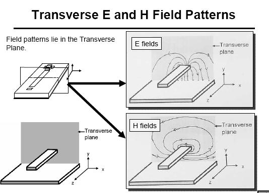
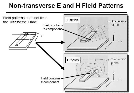
4 Waveguides Transmission lines that consists of two or more conductor may support transverse electromagnetic (TEM) waves It is characterized by the lack of longitudinal field components TEM waves have a uniquely defined voltages, current and characteristics impedance Waveguides, often consisting of a single conductor, support transverse electric (TE) and/or transverse magnetic (TM) waves It is characterized by the presence of longitudinal magnetic or electric, respectively, field components.
5 Electromagnetic wave (1/) x E x Direction of Propagation k z z y B y H y An electromagnetic wave is a travelling wave which has time varying electric and magnetic fields which are perpendicular to each other and the direction of propagation, z S.O. Kasap, Optoelectronics (Prentice Hall)
6
7
8
9
10
 rectangular waveguide (c)")
 fiber")
11 Non-TEM mode waveguide structures (a) rectangular waveguide (c) dielectric slab waveguide (b) circular waveguide, (d) fiber optic waveguide.
12 TERMINOLOGY Kc Cut off wave number: How many wave passes per meter? Cut off frequecy: A waveguide can operate a certain frequency is called cutoff frequency. It is act as a high pass filter. Below this frequency attenuation occurs and above which propagation takes place. Each set of integers m and n gives a different field pattern or mode, referred to as TMmn mode in the wave guide. Integer m equals the number of half cycle variations in the x direction and n in the y direction. The dominant mode is the mode with lowest cut off frequency. Mode: There are a number of ways in which electrical energy can propagate along a wave guide. All these modes must satisfy certain boundary conditions. TEM=Waves in free space known as transverse electromgnetic (TEM). Transmission lines that consist of two or more conductors may support TEM waves, characterize by lack of longitudinal field components. Waveguides, often consisting of a single conductor support transverse electric (TE) and/or TM waves, characterized by the presence of longitudinal magnetic or electric field component.
13 General solutions for TEM, TE, AND TM Waves General solutions to Maxwell equation for the specific case of TEM, TE and TM wave propagation in waveguides. Conductor boundaries that are parallel to the z-axis. The wavenumber, k k k=is the unbounded propagation wave number Cutoff wavenumber, k c k k If dielectric loss is present, c Where, β = phase constant) o r ( 1 j tan )
14 TEM Waves Transverse electromagnetic (TEM) waves are characterized by E z = H z = 0. The wave impedance of a TEM mode can be found as the ratio of the transverse electric and magnetic fields: Z TEM E H x y The other pair of transverse field components Z TEM H E x y
15 The procedure for analyzing a TEM line can be summarized as: Solve Laplace s equation which contain several unknown constants Find these constants by applying the boundary conditions for the known voltages on the conductors Compute e, E,h,H Compute V from I The characteristic impedance is given by Z o = V/I
16 TE Waves The starting point will be the homogenous wave equation. Transverse electric (TE) waves, (also referred to as H-waves) E z =0 and H z 0 The TE wave impedance can be found as Z TE E H x y H E x y k Which is seen to be frequency dependent TE waves can be supported inside closed conductors, as well as between two or more conductors.
17 TM Waves TM waves (transverse magnetic) also referred to as E-waves are characterized E z 0 and H z =0 The TM wave impedance can be found as Z TM E H x y H E x y k Which is frequency dependent TM waves can be supported inside closed conductors, as well as between two or more conductors.
18 Attenuation Due to Dielectric Loss Attenuation in a transmission line or waveguide can be caused by either dielectric loss or conductor loss. If d is the attenuation constant due to dielectric loss, and c is the attenuation constant due to conductor loss, then the total attenuation constant is = d + c. If the line or guide is completely filled with a homogeneous dielectric, the attenuation due to lossy dielectric can be calculated from the propagation constant, and this result will apply to any guide or line with a homogenous dielectric filling.
19 In practice, most dielectric materials have a very small loss (tan << 1) so these expression can be reduces to: ) tan (1 j k k k j r o o c c d j k k k jk k k jk k k c c c tan tan tan Using the complex dielectric constant allows the complex propagation constant to be written as
20 The real wave number in the absence of loss is o o r k c k j (phase constant) The result applies to any TE or TM wave; If the guide is completely filled with the dielectric, it can also be used for TEM (k c = 0, = k) kc d d k k tan tan Np/m (TEM waves)
21 RECTANGULAR WAVEGUIDE Rectangular waveguides were one of the earliest types of transmission lines used to transport microwave signals and are still used today for many applications. The hollow rectangular waveguide can propagate TM and TE modes, but not TEM waves, since only one conductor is present. We will see that the TE and TM modes of a rectangular waveguide have cutoff frequencies below which propagation is not possible, similar to the TM and TE modes of the parallel plate guide.


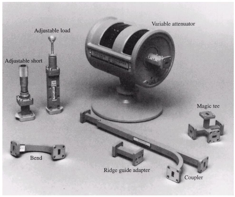
22 Photograph of Ka-band (WR-8) rectangular waveguide components.
23
24
25 TE Mode It is characterized by fields E z =

26 TE Mode It is characterized by fields E z =0. The guide is filled with a material of permittivity and permeability. Waveguide along the x-axis, so that a>b. Fig: Geometry of a rectangular waveguide
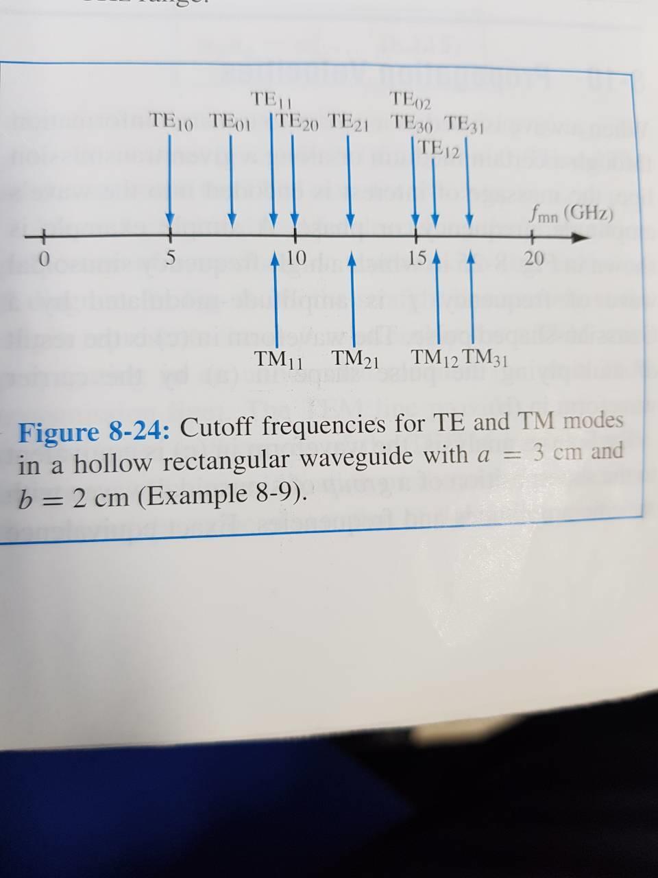
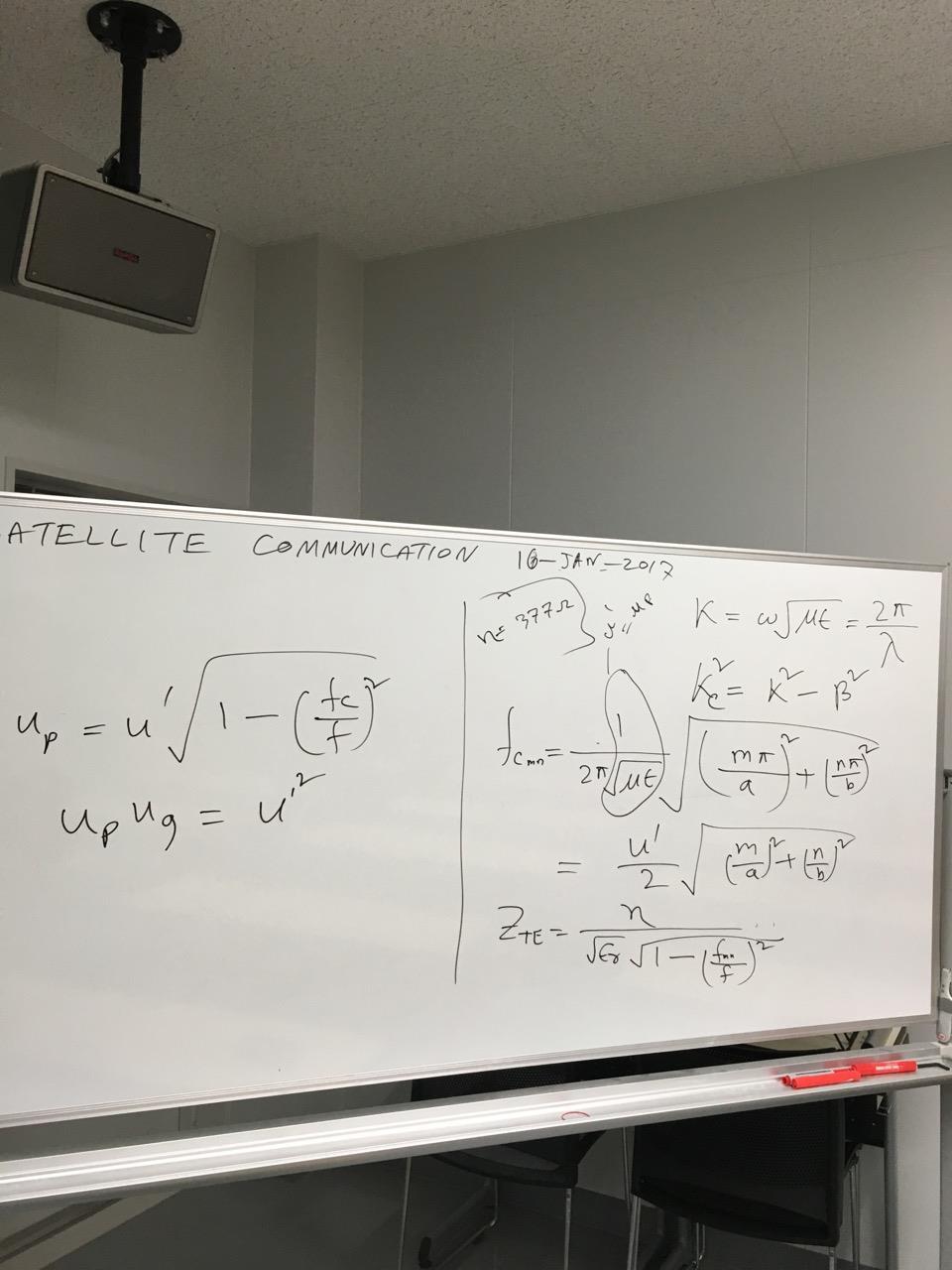
27 The propagation constant; m n k kc k a b Cutoff frequency, f cmn f c mn k c 1 m a n b Or f c u ' m n a b Where, u p = u = 1 με lossless = phase velocity of the uniform plane wave in the dielectric medium (σ = 0, μ, ε) filling the waveguide. The cutoff wavelength λ c is given by λ c =u /fc.
28 The mode with the lowest cutoff frequency is called the dominant mode. Since we have assumed a>b, the lowest f cmn occurs for the TE 10 (m=1, n=0). for TE, (m,n) may be (0,1) or (1,0) but not (0,0). Both m and n cannot be zero at the same time because this will force the filed component to vanish.
29 From the homogenous wave equation E E x = jωμ nπ k c b H mπx 0 Cos Sin( nπy a b ) e jβz This equation consists of cosine and sine component. So all the fields will not vanish if m and n assume a value of 0. Thus the TE 10 mode is the dominant. There is no TE 00 mode. 1 f c 10 a At a given operation f, only those modes having f c <f will propagate. Modes with f c >f will lead to an imaginary β, meaning that all field component will decay exponentially away from the source of excitation. Such modes are referred to as cutoff, or evanescent modes.
30 If more than one mode is propagating, the waveguide is said to be overmoded. Wave impedance the ration can be constituted the wave impedance in the guide ; Z TE E H x y H E x y k Type equation here. Z TE = η 1 (fmn/f) = η r 1 (fmn/f) η= μ/ε ηo = μ o ε o 10π = 377 η=the intrinsic impedance of the dielectric material filling the guide η 0 =the intrinsic impedance of the free space
31 Guide wavelength g k g is thus greater than. the wavelength of a plane wave in the filling medium. Phase velocity u p k 1/ This shows u p u (un bounded medium). If u =c, then u p is greater than the speed of light in vacuum. The group velocity u g is the velocity with which the resultant repeated reflected waves are traveling down the guide and is given u g The group velocity in the guide is always less than or equal to u. So it is evident that U p u g =u Which is greater than the speed of light (plane wave) in the filling medium. In the vast majority of applications the operating frequency and guide dimensions are chosen so that only the dominant TE 10 mode will propagate. fc u' 1 f
32 Which is greater than the speed of light (plane wave) in the filling medium. In the vast majority of applications the operating frequency and guide dimensions are chosen so that only the dominant TE 10 mode will propagate.
33 The attenuation due to conductor loss for the TE 10 mode Np/m ) ( ) / / ( k a b k b a R b a a a b R P P s s l c
34 TM Modes Characterized by fields with H z =???????
35 TM Modes Characterized by fields with H z =0 while E z must satisfy the reduced wave equation. Propagation constant c From the homophonous wave equation E k k k Ez = e z e jβz = E 0 Sin mπx Sin( nπy a b ) e jβz As the equation consists of sine component only so a value of zero for m or n will become zero and all other field component will vanish as well. Cutoff frequency is same as that of the TE mn mode. The lowest order TM mn to propagete is the TM 11 mode. There is no TM 00, TM 01, or TM 10 modes. (as the filed expression for E and H are identically zero if either m or n is zero) m a n b
36 Having a cutoff frequency for TM 11 f c 1 11 a b Which is seen to be larger than f c10 forte 10 mode Wave impedance can be computed in the same way as for the TE modes. Z TM E H x y H E x y k Figure summarizes results for TE and TM wave propagation in rectangular waveguide.

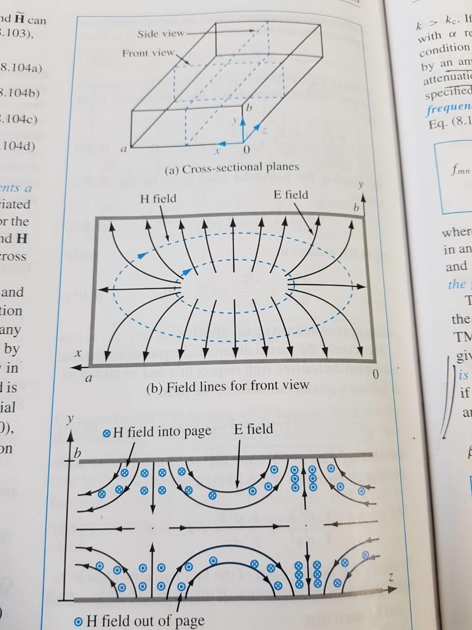
37 Figure : Field lines for some of the lower order modes of a rectangular waveguide.
38
39 Problem 1: A standard air-filled rectangular waveguide with dimensions a = cm, b = cm is fed by a 4-GHz carrier from a coaxial cable. Determine if a TE 10 mode will be propagated. If so, calculate the phase velocity and the group velocity.
40 Problem (a). Show that a rectangular waveguide does not support TM 10 and TM 01 modes. (b) Explain the difference TE mn and TM mn

41 Show that a rectangular waveguide does not support TM10 and TM01 modes. (b) Explain the difference TE mn and TM mn
42 Problem : A tunnel is modeled as an air-filled metallic rectangular waveguide with dimensions a = 8 m and b = 16 m. Determine whether the tunnel will pass: (a) a 1.5-MHz AM broadcast signal, (b) a 10-MHz FM broadcast signal.
43 Problem 3: Design an air-filled rectangular waveguide with the cut-off frequency of a TE 10 mode, f cte10 = 5 GHz whereas the TE 01 mode, f cte01 = 1 GHz.
44 Problem 4: A X3 cm waveguide is filled with a dielectric material with ε r =5. If the waveguide operates at 0 GHz with TE 11 mode, find the a) The cut off frequency
45 Problem 5: A waveguide, with dimensions a = 1 cm and b =0.7 cm, is to be used at 0 GHz. Determine the wave impedance for the dominant mode when i) the guide is empty, and ii) the guide is filled with polyethylene (whose ε r =:5).
46 Problem 6: A hollow rectangular waveguide is used to transmit signals at a carrier frequency of 6 GHz. Design the waveguide so that the cut-off frequency of the dominant TE mode is lower than the carrier by 5% and the next mode is at least 5% higher than the carrier frequency.
47 A hollow rectangular waveguide is used to transmit signals at a carrier frequency of 6 GHz. Design the waveguide so that the cut-off frequency of the dominant TE mode is lower than the carrier by 5% and the next mode is at least 5% higher than the carrier frequency.
48 THANK YOU
Waveguides GATE Problems
 Waveguides GATE Problems One Mark Questions. The interior of a 20 20 cm cm rectangular waveguide is completely 3 4 filled with a dielectric of r 4. Waves of free space wave length shorter than..can be
Waveguides. Metal Waveguides. Dielectric Waveguides
 Waveguides Waveguides, like transmission lines, are structures used to guide electromagnetic waves from point to point. However, the fundamental characteristics of waveguide and transmission line waves
TOPIC 2 WAVEGUIDE AND COMPONENTS
 TOPIC 2 WAVEGUIDE AND COMPONENTS COURSE LEARNING OUTCOME (CLO) CLO1 Explain clearly the generation of microwave, the effects of microwave radiation and the propagation of electromagnetic in a waveguide
EC TRANSMISSION LINES AND WAVEGUIDES TRANSMISSION LINES AND WAVEGUIDES
 TRANSMISSION LINES AND WAVEGUIDES UNIT I - TRANSMISSION LINE THEORY 1. Define Characteristic Impedance [M/J 2006, N/D 2006] Characteristic impedance is defined as the impedance of a transmission line measured
Lec7 Transmission Lines and waveguides (II)
") Lec7 Transmission Lines and waveguides (II) 3.4 CIRCULAR WAVEGUIDE A hollow, round metal pipe also supports TE and TM waveguide modes. we can derive the cylindrical components of the transverse fields
Lec7 Transmission Lines and waveguides (II) 3.4 CIRCULAR WAVEGUIDE A hollow, round metal pipe also supports TE and TM waveguide modes. we can derive the cylindrical components of the transverse fields
EC Transmission Lines And Waveguides
 EC6503 - Transmission Lines And Waveguides UNIT I - TRANSMISSION LINE THEORY A line of cascaded T sections & Transmission lines - General Solution, Physical Significance of the Equations 1. Define Characteristic
UNIT - V WAVEGUIDES. Part A (2 marks)
") Part A (2 marks) UNIT - V WAVEGUIDES 1. What is the need for guide termination? (Nov / Dec 2011) To avoid reflection loss. The termination should provide a wave impedance equal to that of the transmission
Part A (2 marks) UNIT - V WAVEGUIDES 1. What is the need for guide termination? (Nov / Dec 2011) To avoid reflection loss. The termination should provide a wave impedance equal to that of the transmission
Unit 5 Waveguides P a g e 1
 Unit 5 Waveguides P a g e Syllabus: Introduction, wave equation in Cartesian coordinates, Rectangular waveguide, TE, TM, TEM waves in rectangular guides, wave impedance, losses in wave guide, introduction
Rectangular waveguides
 Introduction Rectangular waveguides Waveguides are transmission lines commonly used in electronics, especially in higher frequency ranges like microwaves. A waveguide can be simply described as a metal
EC6503 Transmission Lines and WaveguidesV Semester Question Bank
 UNIT I TRANSMISSION LINE THEORY A line of cascaded T sections & Transmission lines General Solution, Physicasignificance of the equations 1. Derive the two useful forms of equations for voltage and current
Electromagnetic Wave Analysis of Waveguide and Shielded Microstripline 1 Srishti Singh 2 Anupma Marwaha
 Electromagnetic Wave Analysis of Waveguide and Shielded Microstripline 1 Srishti Singh 2 Anupma Marwaha M.Tech Research Scholar 1, Associate Professor 2 ECE Deptt. SLIET Longowal, Punjab-148106, India
ECSE 352: Electromagnetic Waves
 December 2008 Final Examination ECSE 352: Electromagnetic Waves 09:00 12:00, December 15, 2008 Examiner: Zetian Mi Associate Examiner: Andrew Kirk Student Name: McGill ID: Instructions: This is a CLOSED
FINAL EXAM 12/12/03 EECS FALL 2003
 EECS 412 - FALL 2003 FINAL EXAM 12/12/03 NAME: CWRUnet e-mail address: IMPORTANT INFORMATION: 1. All questions are worth the same. 2. Exam is due December 12 th at 12 noon in Glennan 518. Possible 1. 10
Microwave and optical systems Introduction p. 1 Characteristics of waves p. 1 The electromagnetic spectrum p. 3 History and uses of microwaves and
 Microwave and optical systems Introduction p. 1 Characteristics of waves p. 1 The electromagnetic spectrum p. 3 History and uses of microwaves and optics p. 4 Communication systems p. 6 Radar systems p.
04th - 16th August, th International Nathiagali Summer College 1 CAVITY BASICS. C. Serpico
 39th International Nathiagali Summer College 1 CAVITY BASICS C. Serpico 39th International Nathiagali Summer College 2 Outline Maxwell equations Guided propagation Rectangular waveguide Circular waveguide
Microwave Engineering
 Microwave Circuits 1 Microwave Engineering 1. Microwave: 300MHz ~ 300 GHz, 1 m ~ 1mm. a. Not only apply in this frequency range. The real issue is wavelength. Historically, as early as WWII, this is the
2/18/ Transmission Lines and Waveguides 1/3. and Waveguides. Transmission Line A two conductor structure that can support a TEM wave.
 2/18/2009 3 Transmission Lines and Waveguides 1/3 Chapter 3 Transmission Lines and Waveguides First, some definitions: Transmission Line A two conductor structure that can support a TEM wave. Waveguide
 VALLIAMMAI ENGINEERING COLLEGE SRM Nagar, Kattankulathur-603 203 DEPARTMENT OF ELECTRONICS AND COMMUNICATION ENGINEERING EC6503 TRANSMISSION LINES AND WAVEGUIDES YEAR / SEMESTER: III / V ACADEMIC YEAR:
1. Evolution Of Fiber Optic Systems
 OPTICAL FIBER COMMUNICATION UNIT-I : OPTICAL FIBERS STRUCTURE: 1. Evolution Of Fiber Optic Systems The operating range of optical fiber system term and the characteristics of the four key components of
A Mode Based Model for Radio Wave Propagation in Storm Drain Pipes
 PIERS ONLINE, VOL. 4, NO. 6, 008 635 A Mode Based Model for Radio Wave Propagation in Storm Drain Pipes Ivan Howitt, Safeer Khan, and Jumanah Khan Department of Electrical and Computer Engineering The
We are IntechOpen, the world s leading publisher of Open Access books Built by scientists, for scientists. International authors and editors
 We are IntechOpen, the world s leading publisher of Open Access books Built by scientists, for scientists 3,900 116,000 120M Open access books available International authors and editors Downloads Our
Fiber Optic Communication Systems. Unit-04: Theory of Light. https://sites.google.com/a/faculty.muet.edu.pk/abdullatif
 Unit-04: Theory of Light https://sites.google.com/a/faculty.muet.edu.pk/abdullatif Department of Telecommunication, MUET UET Jamshoro 1 Limitations of Ray theory Ray theory describes only the direction
RAJIV GANDHI COLLEGE OF ENGINEERING AND TECHNOLOGY Kirumampakkam,Puducherry DEPARTMENT OF ELECTRONICS AND COMMUNICATION ENGINEERING
 RAJIV GANDHI COLLEGE OF ENGINEERING AND TECHNOLOGY Kirumampakkam,Puducherry-607402 DEPARTMENT OF ELECTRONICS AND COMMUNICATION ENGINEERING QUESTION BANK FOR EC T55 - TRANSMISSION LINES AND WAVEGUIDES G.LAXMINARAYANAN,
ELEC4604. RF Electronics. Experiment 2
 ELEC4604 RF Electronics Experiment MICROWAVE MEASUREMENT TECHNIQUES 1. Introduction and Objectives In designing the RF front end of a microwave communication system it is important to appreciate that the
Fundamentals of Electromagnetics With Engineering Applications by Stuart M. Wentworth Copyright 2005 by John Wiley & Sons. All rights reserved.
 Figure 7-1 (p. 339) Non-TEM mmode waveguide structures include (a) rectangular waveguide, (b) circular waveguide., (c) dielectric slab waveguide, and (d) fiber optic waveguide. Figure 7-2 (p. 340) Cross
Progress In Electromagnetics Research, Vol. 113, , 2011
 Progress In Electromagnetics Research, Vol. 113, 143 160, 2011 BROADBAND COMPLEX PERMITTIVITY MEASUREMENT OF LOW LOSS MATERIALS OVER LARGE TEMPERATURE RANGES BY STRIPLINE RESONATOR CAVITY USING SEGMENTATION
University of KwaZulu-Natal
 University of KwaZulu-Natal School of Engineering Electrical, Electronic & Computer Engineering Instructions to Candidates: UNIVERSITY EXAMINATIONS DECEMBER 2016 ENEL3EM: EM THEORY Time allowed: 2 hours
Γ L = Γ S =
 TOPIC: Microwave Circuits Q.1 Determine the S parameters of two port network consisting of a series resistance R terminated at its input and output ports by the characteristic impedance Zo. Q.2 Input matching
DESIGN AND FABRICATION OF CAVITY RESONATORS
 &2@?%3 DESIGN AND FABRICATION OF CAVITY RESONATORS CHAPTER 3 DESIGN AND FABRICATION OFCAVITY RESONATORS 3.1 Introduction In the cavity perturbation techniques, generally rectangular or cylindrical waveguide
MICROWAVE WAVEGUIDES and COAXIAL CABLE
 MICROWAVE WAVEGUIDES and COAXIAL CABLE In general, a waveguide consists of a hollow metallic tube of arbitrary cross section uniform in extent in the direction of propagation. Common waveguide shapes are
SRI VENKATESWARA COLLEGE OF ENGINEERING DEPARTMENT OF ELECTRONICS AND COMMUNICATION ENGINEERING Date : UNIVERSITY QUESTIONS AND ANSWERS
 SRI VENKATESWARA COLLEGE OF ENGINEERING DEPARTMENT OF ELECTRONICS AND COMMUNICATION ENGINEERING Date : 02.07.2015 UNIVERSITY QUESTIONS AND ANSWERS Subject : Transmission lines & Wave Guides Sub Code :
Projects in microwave theory 2009
 Electrical and information technology Projects in microwave theory 2009 Write a short report on the project that includes a short abstract, an introduction, a theory section, a section on the results and
7. Experiment K: Wave Propagation
 7. Experiment K: Wave Propagation This laboratory will be based upon observing standing waves in three different ways, through coaxial cables, in free space and in a waveguide. You will also observe some
INTRODUCTION OF WAVEGUIDES
 INTRODUCTION OF WAVEGUIDES Under guidance of Joydeep Sengupta sir VNIT BT14ECE031 CHARAN SAI KATAKAM 1 INTRODUCTION TO WAVEGUIDES In a waveguide energy is transmitted in the form of electromagnetic waves
Dielectric Circular Waveguide Loaded with Dielectric Material
 Dielectric Circular Waveguide Loaded with Dielectric Material Dimple N. Agrawal 1, Raj Hakani 2 PG Student, Dept. of Electronics and Communication, Silver Oak College of Engineering and Technology, Ahmedabad,
Projects in microwave theory 2017
 Electrical and information technology Projects in microwave theory 2017 Write a short report on the project that includes a short abstract, an introduction, a theory section, a section on the results and
Guided Propagation Along the Optical Fiber. Xavier Fernando Ryerson University
 Guided Propagation Along the Optical Fiber Xavier Fernando Ryerson University The Nature of Light Quantum Theory Light consists of small particles (photons) Wave Theory Light travels as a transverse electromagnetic
Waveguides and Optical Fibers
 Waveguides and Optical Fibers Dielectric Waveguides Light Light Light n n Light n > n A planar dielectric waveguide has a central rectangular region of higher refractive index n than the surrounding region
Lecturer Note. Lecturer-10
 Lecturer Note Sub: MWE Subject code: PCEC 4402 Sem: 8 th Prepared by: Mr. M. R. Jena Lecturer-10 Components in a signal flow graph Nodes: each port, i, of a microwave network has two nodes, a, and b. Node
ECE 3065: Electromagnetic Applications Final Exam (Spring 2004)
") Name: GTID: ECE 3065: Electromagnetic Applications Final Exam (Spring 2004) Please read all instructions before continuing with the test. This is a closed notes, closed book, closed calculator, closed
Name: GTID: ECE 3065: Electromagnetic Applications Final Exam (Spring 2004) Please read all instructions before continuing with the test. This is a closed notes, closed book, closed calculator, closed
Propagation Mechanism
 Propagation Mechanism ELE 492 FUNDAMENTALS OF WIRELESS COMMUNICATIONS 1 Propagation Mechanism Simplest propagation channel is the free space: Tx free space Rx In a more realistic scenario, there may be
Guided Propagation Along the Optical Fiber. Xavier Fernando Ryerson Comm. Lab
 Guided Propagation Along the Optical Fiber Xavier Fernando Ryerson Comm. Lab The Nature of Light Quantum Theory Light consists of small particles (photons) Wave Theory Light travels as a transverse electromagnetic
Introduction: Planar Transmission Lines
 Chapter-1 Introduction: Planar Transmission Lines 1.1 Overview Microwave integrated circuit (MIC) techniques represent an extension of integrated circuit technology to microwave frequencies. Since four
R.K.YADAV. 2. Explain with suitable sketch the operation of two-cavity Klystron amplifier. explain the concept of velocity and current modulations.
 Question Bank DEPARTMENT OF ELECTRONICS AND COMMUNICATION SUBJECT- MICROWAVE ENGINEERING(EEC-603) Unit-III 1. What are the high frequency limitations of conventional tubes? Explain clearly. 2. Explain
ELECTROMAGNETIC WAVES AND ANTENNAS
 Syllabus ELECTROMAGNETIC WAVES AND ANTENNAS - 83888 Last update 20-05-2015 HU Credits: 4 Degree/Cycle: 1st degree (Bachelor) Responsible Department: Applied Phyisics Academic year: 1 Semester: 2nd Semester
I.E.S-(Conv.)-1996 Some useful data:
-1996 Some useful data:") I.E.S-(Conv.)-1996 ELECTRONICS AND TELECOMMUNICATION ENGINEERING PAPER - I Time allowed: 3 Hours Maximum Marks : 200 Candidates should attempt question ONE which is compulsory and any FOUR of the remaining
I.E.S-(Conv.)-1996 ELECTRONICS AND TELECOMMUNICATION ENGINEERING PAPER - I Time allowed: 3 Hours Maximum Marks : 200 Candidates should attempt question ONE which is compulsory and any FOUR of the remaining
(i) Determine the admittance parameters of the network of Fig 1 (f) and draw its - equivalent circuit.
 Determine the admittance parameters of the network of Fig 1 (f) and draw its - equivalent circuit.") I.E.S-(Conv.)-1995 ELECTRONICS AND TELECOMMUNICATION ENGINEERING PAPER - I Some useful data: Electron charge: 1.6 10 19 Coulomb Free space permeability: 4 10 7 H/m Free space permittivity: 8.85 pf/m Velocity
I.E.S-(Conv.)-1995 ELECTRONICS AND TELECOMMUNICATION ENGINEERING PAPER - I Some useful data: Electron charge: 1.6 10 19 Coulomb Free space permeability: 4 10 7 H/m Free space permittivity: 8.85 pf/m Velocity
COAXIAL / CIRCULAR HORN ANTENNA FOR A STANDARD
 COAXIAL / CIRCULAR HORN ANTENNA FOR 802.11A STANDARD Petr Všetula Doctoral Degree Programme (1), FEEC BUT E-mail: xvsetu00@stud.feec.vutbr.cz Supervised by: Zbyněk Raida E-mail: raida@feec.vutbr.cz Abstract:
Physics 102: Lecture 14 Electromagnetic Waves
 Physics 102: Lecture 14 Electromagnetic Waves Physics 102: Lecture 14, Slide 1 Review: Phasors & Resonance At resonance Z is minimum (=R) I max is maximum (=V gen,max /R) V gen is in phase with I X L =
Objectives of transmission lines
 Introduction to Transmission Lines Applications Telephone Cable TV (CATV, or Community Antenna Television) Broadband network High frequency (RF) circuits, e.g., circuit board, RF circuits, etc. Microwave
Dual-band Antenna Feed Solution for 5G. A dual-band coaxial- and waveguide fed antenna feed for reflector LUKAS MARED
 Dual-band Antenna Feed Solution for 5G A dual-band coaxial- and waveguide fed antenna feed for reflector antenna systems Master s thesis in Wireless, photonics and space engineering LUKAS MARED Department
VALLIAMMAI ENGINEERING COLLEGE
 VALLIAMMAI ENGINEERING COLLEGE SRM Nagar, Kattankulathur 603 203 DEPARTMENT OF ELECTRONICS AND COMMUNICATION ENGINEERING QUESTION BANK V SEMESTER EC6503 TRANSMISSION LINES AND WAVEGUIDES Regulation 2013
USE OF MICROWAVES FOR THE DETECTION OF CORROSION UNDER INSULATION
 USE OF MICROWAVES FOR THE DETECTION OF CORROSION UNDER INSULATION R. E. JONES, F. SIMONETTI, M. J. S. LOWE, IMPERIAL COLLEGE, London, UK I. P. BRADLEY, BP Exploration and Production Company, Sunbury on
6.014 Lecture 14: Microwave Communications and Radar
 6.014 Lecture 14: Microwave Communications and Radar A. Overview Microwave communications and radar systems have similar architectures. They typically process the signals before and after they are transmitted
Department of Electrical Engineering University of North Texas
 Name: Shabuktagin Photon Khan UNT ID: 10900555 Instructor s Name: Professor Hualiang Zhang Course Name: Antenna Theory and Design Course ID: EENG 5420 Email: khan.photon@gmail.com Department of Electrical
Guided Propagation Along the Optical Fiber
 Guided Propagation Along the Optical Fiber The Nature of Light Quantum Theory Light consists of small particles (photons) Wave Theory Light travels as a transverse electromagnetic wave Ray Theory Light
Lecture 38: MON 24 NOV Ch.33 Electromagnetic Waves
 Physics 2113 Jonathan Dowling Heinrich Hertz (1857 1894) Lecture 38: MON 24 NOV Ch.33 Electromagnetic Waves Maxwell Equations in Empty Space: E da = 0 S B da = 0 S C C B ds = µ ε 0 0 E ds = d dt d dt S
Exercise problems of topic 1: Transmission line theory and typical waveguides
 Exercise problems of topic 1: Transmission line theory and typical waveguides Return your answers in the contact sessions on a paper; either handwritten or typescripted. You can return them one by one.
Electromagnetics, Microwave Circuit and Antenna Design for Communications Engineering
 Electromagnetics, Microwave Circuit and Antenna Design for Communications Engineering Second Edition Peter Russer ARTECH HOUSE BOSTON LONDON artechhouse.com Contents Preface xvii Chapter 1 Introduction
Interference and Diffraction of Microwaves
 Interference and Diffraction of Microwaves References: Equipment: Ford, Kenneth W., Classical and Modern Physics Vol2 Xerox College Publishing 1972 pp. 850-871. Pasco Instruction Manual and Experiment
Antennas and Propagation. Chapter 4: Antenna Types
 Antennas and Propagation : Antenna Types 4.4 Aperture Antennas High microwave frequencies Thin wires and dielectrics cause loss Coaxial lines: may have 10dB per meter Waveguides often used instead Aperture
Critical Study of Open-ended Coaxial Sensor by Finite Element Method (FEM)
") International Journal of Applied Science and Engineering 3., 4: 343-36 Critical Study of Open-ended Coaxial Sensor by Finite Element Method (FEM) M. A. Jusoha*, Z. Abbasb, M. A. A. Rahmanb, C. E. Mengc,
International Journal of Applied Science and Engineering 3., 4: 343-36 Critical Study of Open-ended Coaxial Sensor by Finite Element Method (FEM) M. A. Jusoha*, Z. Abbasb, M. A. A. Rahmanb, C. E. Mengc,
A NOVEL DUAL-BAND PATCH ANTENNA FOR WLAN COMMUNICATION. E. Wang Information Engineering College of NCUT China
 Progress In Electromagnetics Research C, Vol. 6, 93 102, 2009 A NOVEL DUAL-BAND PATCH ANTENNA FOR WLAN COMMUNICATION E. Wang Information Engineering College of NCUT China J. Zheng Beijing Electro-mechanical
6.014 Lecture 18: Optical Communications
 6.014 Lecture 18: Optical Communications A. Overview Optical communications is as old as smoke signals, modulated campfires, and mirrors reflecting sunlight. Today it is even more important, particularly
TEM Cell design for Material Characterization
 Master s Thesis TEM Cell design for Material Characterization Edward Lindenholst Filip Olsson Department of Electrical and Information Technology, Faculty of Engineering, LTH, Lund University, 2016. main
BANDWIDTH ENHANCEMENT OF CIRCULAR MICROSTRIP ANTENNAS
 BANDWIDTH ENHANCEMENT OF CIRCULAR MICROSTRIP ANTENNAS Ali Hussain Ali Yawer 1 and Abdulkareem Abd Ali Mohammed 2 1 Electronic and Communications Department, College of Engineering, Al- Nahrain University,
University of KwaZulu-Natal
 University of KwaZulu-Natal School of Engineering Electrical, Electronic & Computer Engineering UNIVERSITY EXAMINATIONS NOVEMBER 2015 ENEL3EM: EM THEORY Time allowed: 2 hours Instructions to Candidates:
Fiber Optic Communications Communication Systems
 INTRODUCTION TO FIBER-OPTIC COMMUNICATIONS A fiber-optic system is similar to the copper wire system in many respects. The difference is that fiber-optics use light pulses to transmit information down
Lecture #3 Microstrip lines
 November 2014 Ahmad El-Banna Benha University Faculty of Engineering at Shoubra Post-Graduate ECE-601 Active Circuits Lecture #3 Microstrip lines Instructor: Dr. Ahmad El-Banna Agenda Striplines Forward
Lab Manual Experiment No. 2
 Lab Manual Experiment No. 2 Aim of Experiment: Observe the transient phenomenon of terminated coaxial transmission lines in order to study their time domain behavior. Requirement: You have to install a
FATIMA MICHAEL COLLEGE OF ENGINEERING AND TECHNOLOGY/ DEPARTMENT OF ECE EC 2305: Transmission Lines and Wave Guides-Question Bank UNIT-I/ PART A
 FATIMA MICHAEL COLLEGE OF ENGINEERING AND TECHNOLOGY/ DEPARTMENT OF ECE EC 2305: Transmission Lines and Wave Guides-Question Bank UNIT-I/ PART A S.No Question Exam 1. For a symmetrical network, define
UWB leaky lens antenna design and simulation for waveguide measurements
 Master s Thesis UWB leaky lens antenna design and simulation for waveguide measurements By Liu Jin Department of Electrical and Information Technology Faculty of Engineering, LTH, Lund University SE-221
Introduction to the Technological, Pedagogical and Content Knowledge TPACK) Curriculum
 Curriculum") Introduction to the Technological, Pedagogical and Content Knowledge TPACK) Curriculum The TPACK curriculum developed by Teaching Learning Centre, Indian Institute of Technology-Madras (IIT Madras), is
Introduction to the Technological, Pedagogical and Content Knowledge TPACK) Curriculum The TPACK curriculum developed by Teaching Learning Centre, Indian Institute of Technology-Madras (IIT Madras), is
Fields and Waves I. Lecture 26. Intro to Antennas & Propagation K. A. Connor
 Fields and Waves I Lecture 26 Intro to Antennas & Propagation K. A. Connor Electrical, Computer, and Systems Engineering Department Rensselaer Polytechnic Institute, Troy, NY These Slides Were Prepared
THE ELECTROMAGNETIC FIELD THEORY. Dr. A. Bhattacharya
 1 THE ELECTROMAGNETIC FIELD THEORY Dr. A. Bhattacharya The Underlying EM Fields The development of radar as an imaging modality has been based on power and power density It is important to understand some
Monoconical RF Antenna
 Page 1 of 8 RF and Microwave Models : Monoconical RF Antenna Monoconical RF Antenna Introduction Conical antennas are useful for many applications due to their broadband characteristics and relative simplicity.
Microwave Magnetics. Graduate Course Electrical Engineering (Communications) 2 nd Semester, Sharif University of Technology
 2 nd Semester, Sharif University of Technology") Microwave Magnetics Graduate Course Electrical Engineering (Communications) 2 nd Semester, 389-39 Sharif University of Technology General information Contents of lecture 8: Waveguide resonators General
Microwave Magnetics Graduate Course Electrical Engineering (Communications) 2 nd Semester, 389-39 Sharif University of Technology General information Contents of lecture 8: Waveguide resonators General
Ground Penetrating Radar
 Ground Penetrating Radar Begin a new section: Electromagnetics First EM survey: GPR (Ground Penetrating Radar) Physical Property: Dielectric constant Electrical Permittivity EOSC 350 06 Slide Di-electric
SUPPLEMENTARY INFORMATION
 A full-parameter unidirectional metamaterial cloak for microwaves Bilinear Transformations Figure 1 Graphical depiction of the bilinear transformation and derived material parameters. (a) The transformation
Cut-off of Resonant Modes in Truncated Conical Cavities
 Cut-off of Resonant Modes in Truncated Conical Cavities José J. Rodal, Ph.D. June 2015 Although the fact that a truncated conical cavity displays an absence of sharp cut-off frequencies has been remarked
6.013 Lecture 19: Waveguides and Applications
 6.013 Lecture 19: Waveguides and Applications A. Parallel-Plate Waveguides Parallel-plate waveguides trap propagating energy between two perfectly conducting parallel plates. The electromagnetic waves
DEPARTMENT OF ELECTRONICS AND COMMUNICATION ENGINEERING SUBJECT CODE: EC 1305 SUBJECT: TRANSMISSION LINES AND WAVEGUIDES (FOR FIFTH SEMESTER ECE)
") DEPARTMENT OF ELECTRONICS AND COMMUNICATION ENGINEERING SUBJECT CODE: EC 1305 SUBJECT: TRANSMISSION LINES AND WAVEGUIDES (FOR FIFTH SEMESTER ECE) TWO MARKS QUESTIONS UNIT I-TRANSMISSION LINE THEORY 1.Define
DEPARTMENT OF ELECTRONICS AND COMMUNICATION ENGINEERING SUBJECT CODE: EC 1305 SUBJECT: TRANSMISSION LINES AND WAVEGUIDES (FOR FIFTH SEMESTER ECE) TWO MARKS QUESTIONS UNIT I-TRANSMISSION LINE THEORY 1.Define
Split waveguide and a waveguide acting as an antenna
 2013-10-01 Department of Physics Olexii Iukhymenko oleksii.iukhymenko@physics.umu.se Computerlab 4 Split waveguide and a waveguide acting as an antenna Introduction: Split waveguide: Picture 1 This is
Index Terms - Attenuation Constant(α), MB-OFDM Signal, Propagation Constant( β), TWI.
, MB-OFDM Signal, Propagation Constant( β), TWI.") Through-The-Wall Propagation and Channel Modeling G. Nagaraja 1,G.Balaji 2 1 Research Scholar in Department of Electronics and Communications Engineering, Shri Venkateshwara University, Gajraula, Amorha,
Through-The-Wall Propagation and Channel Modeling G. Nagaraja 1,G.Balaji 2 1 Research Scholar in Department of Electronics and Communications Engineering, Shri Venkateshwara University, Gajraula, Amorha,
Standing waves. Consider a string with 2 waves of equal amplitude moving in opposite directions. or, if you prefer cos T
 Waves 2 1. Standing waves 2. Transverse waves in nature: electromagnetic radiation 3. Polarisation 4. Dispersion 5. Information transfer and wave packets 6. Group velocity 1 Standing waves Consider a string
MEASUREMENT OF COMPLEX PERMITTIVITY AND COMPLEX PERMEABILITY OF MATERIALS. H. Alenkowicz*, B. Levitas**
 MEAUREMEN OF COMPLEX PERMIIVIY AND COMPLEX PERMEABILIY OF MAERIAL H. Alenkowicz*, B. Levitas** ime Domain measurement of complex permittivity and complex permeability in the 8 to 18 GHz frequency band
A Broadband Low-Loss WR 10 Waveguide to Microstrip Line Transition with T-Shaped Probe
 Progress In Electromagnetics Research Letters, Vol. 73, 17 22, 2018 A Broadband Low-Loss WR 10 Waveguide to Microstrip Line Transition with T-Shaped Probe Gerhard F. Hamberger *, Uwe Siart, and Thomas
Design of a UHF Pyramidal Horn Antenna Using CST
 Volume 114 No. 7 2017, 447-457 ISSN: 1311-8080 (printed version); ISSN: 1314-3395 (on-line version) url: http://www.ijpam.eu ijpam.eu Design of a UHF Pyramidal Horn Antenna Using CST Biswa Ranjan Barik
Keysight Technologies Techniques for Advanced Cable Testing
 Keysight Technologies Techniques for Advanced Cable Testing Using FieldFox handheld analyzers Application Note Transmission lines are used to guide the flow of energy from one point to another. Line types
MICROWAVE ENGINEERING LAB VIVA QUESTIONS AND ANSWERS
 MICROWAVE ENGINEERING LAB VIVA QUESTIONS AND ANSWERS. Why can t conventional tubes be used at microwave frequencies? Conventional tubes can t be used at microwave frequencies because of transit time effect.
Telecommunication Systems February 14 th, 2019
 Telecommunication Systems February 14 th, 019 1 3 4 5 do not write above SURNAME AND NAME ID NUMBER SIGNATURE Problem 1 A radar with zenithal pointing, working at f = 5 GHz, illuminates an aircraft with
Practical Measurements of Dielectric Constant and Loss for PCB Materials at High Frequency
 8 th Annual Symposium on Signal Integrity PENN STATE, Harrisburg Center for Signal Integrity Practical Measurements of Dielectric Constant and Loss for PCB Materials at High Frequency Practical Measurements
Lab 1: Pulse Propagation and Dispersion
 ab 1: Pulse Propagation and Dispersion NAME NAME NAME Introduction: In this experiment you will observe reflection and transmission of incident pulses as they propagate down a coaxial transmission line
Characterization of the Electromagnetic Fields Inside a Wire Mesh Cage for Biotelemetry
 Marquette University e-publications@marquette Master's Theses (2009 -) Dissertations, Theses, and Professional Projects Characterization of the Electromagnetic Fields Inside a Wire Mesh Cage for Biotelemetry
A NOVEL EPSILON NEAR ZERO (ENZ) TUNNELING CIRCUIT USING MICROSTRIP TECHNOLOGY FOR HIGH INTEGRABILITY APPLICATIONS
 TUNNELING CIRCUIT USING MICROSTRIP TECHNOLOGY FOR HIGH INTEGRABILITY APPLICATIONS") Progress In Electromagnetics Research C, Vol. 15, 65 74, 2010 A NOVEL EPSILON NEAR ZERO (ENZ) TUNNELING CIRCUIT USING MICROSTRIP TECHNOLOGY FOR HIGH INTEGRABILITY APPLICATIONS D. V. B. Murthy, A. Corona-Chávez
Progress In Electromagnetics Research C, Vol. 15, 65 74, 2010 A NOVEL EPSILON NEAR ZERO (ENZ) TUNNELING CIRCUIT USING MICROSTRIP TECHNOLOGY FOR HIGH INTEGRABILITY APPLICATIONS D. V. B. Murthy, A. Corona-Chávez
High Power Over-Mode 90 Bent Waveguides for Circular TM 01 and Coaxial TEM Mode Transmission
 Progress In Electromagnetics Research M, Vol. 60, 189 196, 2017 High Power Over-Mode 90 Bent Waveguides for Circular TM 01 and Coaxial TEM Mode Transmission Xiaomeng Li, Xiangqiang Li *, Qingxiang Liu,
Polarized Switchable Microstrip Array Antenna Printed on LiTi Ferrite
 134 Polarized Switchable Microstrip Array Antenna Printed on LiTi Ferrite Naveen Kumar Saxena, Nitendar Kumar 1, Pradeep Kumar Singh Pourush and Sunil Kumar Khah* 2 Microwave Lab, Department of Physics,
DESIGN OF A NOVEL BROADBAND EMC DOUBLE RIDGED GUIDE HORN ANTENNA
 Progress In Electromagnetics Research C, Vol. 39, 225 236, 2013 DESIGN OF A NOVEL BROADBAND EMC DOUBLE RIDGED GUIDE HORN ANTENNA Tenigeer *, Ning Zhang, Jinghui Qiu, Pengyu Zhang, and Yang Zhang School
ωκε ωκε 5.11 Ground Penetrating Radar (GPR)
") 5. Ground Penetrating Radar (GPR) The plane wave solutions we have studied so far have been valid for frequencies and conductivities such that the conduction currents dominate the displacement currents
5. Ground Penetrating Radar (GPR) The plane wave solutions we have studied so far have been valid for frequencies and conductivities such that the conduction currents dominate the displacement currents
Fiber Optic Communication Systems. Unit-05: Types of Fibers. https://sites.google.com/a/faculty.muet.edu.pk/abdullatif
 Unit-05: Types of Fibers https://sites.google.com/a/faculty.muet.edu.pk/abdullatif Department of Telecommunication, MUET UET Jamshoro 1 Optical Fiber Department of Telecommunication, MUET UET Jamshoro