Waveguides. Metal Waveguides. Dielectric Waveguides
|
|
|
- Edwina Sutton
- 6 years ago
- Views:
Transcription
1 Waveguides Waveguides, like transmission lines, are structures used to guide electromagnetic waves from point to point. However, the fundamental characteristics of waveguide and transmission line waves (modes) are quite different. The differences in these modes result from the basic differences in geometry for a transmission line and a waveguide. Waveguides can be generally classified as either metal waveguides or dielectric waveguides. Metal waveguides normally take the form of an enclosed conducting metal pipe. The waves propagating inside the metal waveguide may be characterized by reflections from the conducting walls. The dielectric waveguide consists of dielectrics only and employs reflections from dielectric interfaces to propagate the electromagnetic wave along the waveguide. Metal Waveguides Dielectric Waveguides
2 Comparison of Waveguide and Transmission Line Characteristics Transmission line Two or more conductors separated by some insulating medium (two-wire, coaxial, microstrip, etc.). Normal operating mode is the TEM or quasi-tem mode (can support TE and TM modes but these modes are typically undesirable). No cutoff frequency for the TEM mode. Transmission lines can transmit signals from DC up to high frequency. Significant signal attenuation at high frequencies due to conductor and dielectric losses. Small cross-section transmission lines (like coaxial cables) can only transmit low power levels due to the relatively high fields concentrated at specific locations within the device (field levels are limited by dielectric breakdown). Waveguide Metal waveguides are typically one enclosed conductor filled with an insulating medium (rectangular, circular) while a dielectric waveguide consists of multiple dielectrics. Operating modes are TE or TM modes (cannot support a TEM mode). Must operate the waveguide at a frequency above the respective TE or TM mode cutoff frequency for that mode to propagate. Lower signal attenuation at high frequencies than transmission lines. Metal waveguides can transmit high power levels. The fields of the propagating wave are spread more uniformly over a larger cross-sectional area than the small cross-section transmission line. Large cross-section transmission lines (like power transmission lines) can transmit high power levels. Large cross-section (low frequency) waveguides are impractical due to large size and high cost.
3 General Wave Characteristics as Defined by Maxwell s Equations Given any time-harmonic source of electromagnetic radiation, the phasor electric and magnetic fields associated with the electromagnetic waves that propagate away from the source through a medium characterized by (ì,å) must satisfy the source-free Maxwell s equations (in phasor form) given by The source-free Maxwell s equations can be manipulated into wave equations for the electric and magnetic fields (as was shown in the case of plane waves). These wave equations are where the wavenumber k is real-valued for lossless media and complexvalued for lossy media. The electric and magnetic fields of a general wave propagating in the +z-direction (either unguided, as in the case of a plane wave or guided, as in the case of a transmission line or waveguide) through an arbitrary medium with a propagation constant of ã are characterized by ãz a z-dependence of e. The electric and magnetic fields of the wave may be written in rectangular coordinates as where á is the wave attenuation constant and â is the wave phase constant. The propagation constant is purely imaginary (á = 0, ã = jâ) when the wave travels without attenuation (no losses) or complex-valued when losses are present.
4 The transverse vectors in the general wave field expressions may contain both transverse field components and longitudinal field components. By expanding the curl operator of the source free Maxwell s equations in rectangular coordinates, we note that the derivatives of the transverse field components with respect to z are If we equate the vector components on each side of the two Maxwell curl equations, we find We may manipulate (1) and (2) to solve for the longitudinal field components in terms of the transverse field components.
5 where the constant h is defined by The equations for the transverse fields in terms of the longitudinal fields describe the different types of possible modes for guided and unguided waves.
6 For simplicity, consider the case of guided or unguided waves propagating through an ideal (lossless) medium where k is real-valued. For TEM modes, the only way for the transverse fields to be non-zero with is for h = 0, which yields Thus, for unguided TEM waves (plane waves) moving through a lossless medium or guided TEM waves (waves on a transmission line) propagating on an ideal transmission line, we have ã = jk = jâ. For the waveguide modes (TE, TM or hybrid modes), h cannot be zero since this would yield unbounded results for the transverse fields. Thus, â k for waveguides and the waveguide propagation constant can be written as The propagation constant of a wave in a waveguide (TE or TM waves) has very different characteristics than the propagation constant for a wave on a transmission line (TEM waves). The ratio of h/k in the waveguide mode propagation constant equation can be written in terms of the cutoff frequency f for the given waveguide mode as follows. c The waveguide propagation constant in terms of the waveguide cutoff frequency is
7 An examination of the waveguide propagation constant equation reveals the cutoff frequency behavior of the waveguide modes. ã z á z If f < f c, ã = á (purely real) e = e waves are attenuated (evanescent modes). ã z j â z If f > f c, ã = jâ (purely imaginary) e = e waves are unattenuated (propagating modes). Therefore, in order to propagate a wave down a waveguide, the source must operate at a frequency higher than the cutoff frequency for that particular mode. If a waveguide source is operated at a frequency less than the cutoff frequency of the waveguide mode, then the wave is quickly attenuated in the vicinity of the source.
8 TE and TM Modes in Ideal Waveguides (PEC tube, perfect insulator inside) Waves propagate along the waveguide (+z-direction) within the waveguide through the lossless dielectric. The electric and magnetic fields of the guided waves must satisfy the source-free Maxwell s equations. Assumptions: (1) the waveguide is infinitely long, oriented along the z-axis, and uniform along its length. (2) the waveguide is constructed from ideal materials [perfectly conducting pipe (PEC) is filled with a perfect insulator (lossless dielectric)]. (3) fields are time-harmonic. The cross-sectional size and shape of the waveguide dictates the discrete modes that can propagate along the waveguide. That is, there are only discrete electric and magnetic field distributions that will satisfy the appropriate boundary conditions on the surface of the waveguide conductor. If the single non-zero longitudinal field component associated with a given waveguide mode can be determined for a TM mode, for a TE mode), the remaining transverse field components can be found using the general wave equations for the transverse fields in terms of the longitudinal fields.
9 General waves in an arbitrary medium TE modes in an ideal waveguide TM modes in an ideal waveguide The longitudinal magnetic field of the TE mode and the longitudinal electric field of the TM mode are determined by solving the appropriate boundary value problem for the given waveguide geometry.
10 Ideal Rectangular Waveguide The rectangular waveguide can support either TE or TM modes. The rectangular cross-section (a > b) allows for single-mode operation. Single -mode operation means that only one mode propagates in the waveguide over a given frequency range. A square waveguide cross-section does not allow for single-mode operation. Rectangular Waveguide TM modes The longitudinal electric field of the TM modes within the rectangular waveguide must satisfy the wave equation which expanded in rectangular coordinates is The electric field function may be determined using the separation of variables technique by assuming a solution of the form
11 Inserting the assumed solution into the governing differential equation gives where h = ã + k = k â. Dividing this equation by the assumed solution gives (1) Note that the first term in (1) is a function of x only while the second term is a function of y only. In order for (1) to be satisfied for every x and y within the waveguide, each of the first two terms in the equation must be constants. The original second order partial differential equation dependent on two variables has been separated into two second order ordinary differential equations each dependent on only one variable. The general solutions to the two separate differential equations are
12 The resulting longitudinal electric field for a rectangular waveguide TM mode is The TM boundary conditions for the rectangular waveguide are The application of the boundary conditions yields The resulting product of the constants A and C can be written as a single constant (defined as E o). The number of discrete TM modes is infinite based on the possible values of the indices m and n. An individual TM mode is designated as the TM mn mode. The longitudinal electric field of the TM mode in the rectangular waveguide is given by mn
13 The transverse field components of the TM mn mode are found by differentiating the longitudinal electric field as defined by the standard TM equations. In general, the cutoff frequency will increase as the mode index increases. Thus, in practice, only the lower order modes are important as the waveguide is operated at frequencies below of the cutoff frequencies of the higher order modes.
14 Rectangular Waveguide TE modes The longitudinal magnetic field of the TE modes within the rectangular waveguide must satisfy the same wave equation as the longitudinal electric field of the TM modes: which expanded in rectangular coordinates is The same separation of variables technique used to solve for the longitudinal TM electric field applies to the longitudinal TE magnetic field. Thus, the longitudinal TE magnetic field may be written as To determine the unknown coefficients, we apply the TE boundary conditions. Given no longitudinal electric field for the TE case, the boundary conditions for the transverse electric field components on the walls of the waveguide must be enforced. The TE boundary conditions are:
15 The transverse components of the TE electric field are related to longitudinal magnetic field by the standard TE equations. The application of the TE boundary conditions yields Combining the constants B and D into the constant H o, the resulting longitudinal magnetic field of the TE mode is mn
16 Note that the indices include m = 0 and n = 0 in the TE solution since these values still yield a non-zero longitudinal magnetic field. However, the case of n = m = 0 is not allowed since this would make all of the transverse field components zero. The resulting transverse fields for the waveguide TE modes are where (m = 0, 1, 2,...) and (n = 0, 1, 2,...) but m = n 0 for the TE mn mode. Summary of Rectangular Waveguide Modes Rectangular waveguide mn index pairs (TM ) mn Rectangular waveguide mn index pairs (TE ) mn
17 Rectangular Waveguide TE and TM Mode Parameters The propagation constant in the rectangular waveguide for both the TE and TM waveguide modes (ã ) is defined by mn mn mn The equation for the waveguide propagation constant ã mn can be used to determine the cutoff frequency for the respective waveguide mode. The propagation characteristics of the wave are defined by the relative sizes of the parameters h mn and k. The propagation constant may be written in terms of the attenuation and phase constants as ã = á + jâ so that, mn mn mn if h mn = k ã mn = 0 (á mn = â mn = 0) cutoff frequency if h mn > k ã mn (real), [ã mn= á mn] evanescent modes if h mn < k ã mn (imag.), [ã mn= jâ mn] propagating modes Therefore, the cutoff frequencies for the TE and TM modes in the rectangular waveguide are found by solving
18 Note that the cutoff frequency for a particular rectangular waveguide mode depends on the dimensions of the waveguide (a,b), the material inside the waveguide (ì,å), and the indices of the mode (m,n). The rectangular waveguide must be operated at a frequency above the cutoff frequency for the respective mode to propagate. According to the cutoff frequency equation, the cutoff frequencies of both the TE 10 and TE 01 modes are less than that of the lowest order TM mode (TM 11). Given a > b for the rectangular waveguide, the TE 10 has the lowest cutoff frequency of any of the rectangular waveguide modes and is thus the dominant mode (the first to propagate). Note that the TE 10 and TE 01 modes are degenerate modes (modes with the same cutoff frequency) for a square waveguide. The rectangular waveguide allows one to operate at a frequency above the cutoff of the dominant TE 10 mode but below that of the next highest mode to achieve single mode operation. A waveguide operating at a frequency where more than one mode propagates is said to be overmoded. Example (Rectangular waveguide propagating modes) A rectangular waveguide (a = 2 cm, b = 1 cm) filled with deionized water (ì r =1, å r = 81 ) operates at 3 GHz. Determine all propagating modes and the corresponding cutoff frequencies.
19 Cutoff frequencies - TM modes (GHz) Cutoff frequencies - TE modes (GHz) Mode f (GHz) c TE TE 01, TE TE 11, TM TE 21, TM TE As previously shown, the propagation constant for a given mode can be defined in terms of the cutoff frequency for that mode by The field components, cutoff frequency and propagation constant associated with the dominant TE 10 mode (using the TE mn equations with m =1, n = 0, and ã = jâ ) are: mn 10
20 The corresponding instantaneous fields of the TE 10 mode are determined by jù t multiplying the phasor field components by e and taking the real part of the result. The waveguide wavelength is defined using the same definition as for unguided (TEM) waves [ë = 2ð/â]. However, the size of the waveguide wavelength can be quite different than that of an unguided wave at the same frequency. The wavelength of a TE or TM mode propagating in the rectangular waveguide can be written in terms of the wavelength for an unguided (TEM) wave propagating in the same medium (ì,å) as found inside the waveguide (designated as ë ).
21 The denominator of the rectangular waveguide wavelength equation becomes very small when the operating frequency is very close to the cutoff frequency. This yields a waveguide wavelength which is much longer than that of an unguided wave traveling through the same medium at the same frequency. Conversely, if the operating frequency is very large in comparison to the cutoff frequency, the denominator approaches a value of unity, and the waveguide wavelength is approximately equal to the TEM wavelength. Just as the characteristic (wave) impedance for the TEM modes on a transmission line is defined by a ratio of the transverse electric field to the transverse magnetic field, the wave impedances of the TE and TM waveguide modes can be defined in the same manner. The waveguide wave impedance can be related to the wave impedance of a TEM wave traveling through the same medium (as that inside the waveguide) at the same frequency. The waveguide TE and TM wave impedances are defined by
22 Note that the product of the TE and TM wave impedances is equal to the square of the TEM wave impedance.
23 Waveguide Group Velocity and Phase Velocity The velocity of propagation for a TEM wave (plane wave or transmission line wave) is referred to as the phase velocity (the velocity at which a point of constant phase moves). The phase velocity of a TEM wave is equal to the velocity of energy transport. The phase velocity of a TEM wave traveling in a lossless medium characterized by (ì,å) is given by The phase velocity of TE or TM mode in a waveguide is defined in the same manner as that of a TEM wave (the velocity at which a point of constant phase moves). We will find, however, that the waveguide phase velocity is not equal to the velocity of energy transport along the waveguide. The velocity at which energy is transported down the length of the waveguide is defined as the group velocity. The differences between the waveguide phase velocity and group velocity can be illustrated using the field equations of the TE or TM rectangular waveguide modes. It can be shown that the field components of general TE and TM waveguide modes can be written as sums and differences of TEM waves. Consider the equation for the y-component of the TE mode electric field in a rectangular waveguide. By applying the trigonometric identity: this component of the waveguide electric field can be written as
24 The two terms in the TE field equation above represent TEM waves moving in the directions shown below. Thus, the TE wave in the rectangular waveguide can be represented as the superposition of two TEM waves reflecting from the upper and lower waveguide walls as they travel down the waveguide. For the general TE mn of TM mn waves, the phase velocity of the TEM component is given by
25 Inserting the equation for the waveguide phase constant â mn gives The waveguide phase velocity represents the speed at which points of constant phase of the component TEM waves travel down the waveguide. The waveguide phase velocity is larger than the TEM wave phase velocity given that the square root in the denominator of the waveguide phase velocity equation is less than unity. The relationship between the waveguide phase velocity, waveguide group velocity, and the TEM component wave velocity is shown below.
26 The waveguide group velocity (the velocity of energy transport) is always smaller than the TEM wave phase velocity given the square root term in the numerator of the group velocity equation. Example Given a pair of degenerate modes (TE mn and TM mn) in an air-filled rectangular waveguide with a cutoff frequency of 15 GHz, plot the following parameters as a function of frequency: phase velocity and group velocity, TE wave impedance and TM wave impedance, TEM wavelength and mode wavelength, TEM phase constant and mode phase constant.
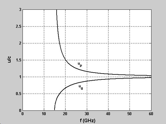
27
28
29 Attenuation in Waveguides Only ideal waveguides have been considered thus far (characterized by a perfect conductor filled with a perfect insulator). The propagating waves in an ideal waveguide suffer no attenuation as the travel down the waveguide. Two loss mechanisms exist in a realistic waveguide: conductor loss and dielectric loss. The fields associated with the propagating waveguide modes produce currents that flow in the walls of the waveguide. Given that the waveguide walls are constructed from an imperfect conductor (ó c < ), the walls act like resistors and dissipate energy in the form of heat. Also, the dielectric within the waveguide is not ideal (ó d > 0) so that dielectric also dissipates energy in the form of heat. The overall attenuation constant á (in units of Np/m) for a realistic waveguide can be written in terms of the two loss components as where á c is the attenuation constant due to conductor loss and á d is the attenuation constant due to dielectric loss. For either TE or TM modes in a rectangular waveguide, the attenuation constant due to dielectric loss is given by
30 The attenuation constant due to conductor loss in a rectangular waveguide depends on the mode type (TE or TM) due to the different components of field present in these modes. The attenuation constant due to conductor losses for the TM mn mode in a rectangular waveguide is given by where is the surface resistance of the waveguide walls and is the skin depth of the waveguide walls at the operating frequency. It is assumed that the waveguide wall thickness is several skin depths such that the wall currents are essentially surface currents. This is an accurate assumption at the typical operating frequencies of waveguides ( GHz) where the skin depth of common conductors like aluminum and copper are on the order of ìm. The attenuation constant due to conductor losses for the TE mn mode in a rectangular waveguide with (n 0) is given by
31 For the special case of (n = 0), the attenuation constant due to conductor losses for the TE mode in a rectangular waveguide is m0 The equation above applies to the dominant rectangular waveguide mode [TE ]. 10 Example (Waveguide attenuation) 7 An aluminum waveguide (a = 4.2 cm, b = 1.5 cm, ó c = /m) 15 filled with teflon (ì r= 1, å r= 2.6, ó d = 10 /m) operates at 4 GHz. Determine (a.) á c and á d for the TE 10 mode (b.) the waveguide loss in db over a distance of 1.5 m.
32 For this problem, we see that the dielectric losses are negligible in comparison to the conductor losses. The waves propagating in the +z direction in the rectangular waveguide vary as Thus, over a distance of 1.5 m, the fields associated with the wave decay according to In terms of db, we find [a loss of db in 1.5m].
33 Cavity Resonators At high frequencies where waveguides are used, lumped element tuned circuits (RLC circuits) are very inefficient. As the element dimensions become comparable to the wavelength, unwanted radiation from the circuit occurs. Waveguide resonators are used in place of the lumped element RLC circuit to provide a tuned circuit at high frequencies. The rectangular waveguide resonator is basically a section of rectangular waveguide which is enclosed on both ends by conducting walls to form an enclosed conducting box. We assume the same cross-sectional dimensions as the rectangular waveguide (a,b) and define the longitudinal length of the resonator as c. Given the conducting walls on the ends of the waveguide, the resonator modes may be described by waveguide modes which are reflected back and forth within the resonator (+z and z directions) to form standing waves. Waveguide (waves in one direction)
34 Cavity (waves in both directions, standing waves) The separation equation for the cavity modes is The cavity boundary conditions (in addition to the boundary conditions satisfied by the rectangular waveguide wave functions) are From the source-free Maxwell s curl equations, the TE and TM boundary conditions on the end walls of the cavity are satisfied if Application of the TE and TM boundary conditions yields
35 The TE and TM modes in the rectangular cavity are then The resonant frequency associated with the TE mnp or TM mnp mode is found from the separation equation to be
36 The lowest order modes in a rectangular cavity are the TM 110, TE 101, and TE 011 modes. Which of these modes is the dominant mode depends on the relative dimensions of the resonator. Example (Cavity resonator) Find the first five resonances of an air-filled rectangular cavity with dimensions of a = 5 cm, b = 4 cm and c = 10 cm (c > a > b ).
37 The quality factor (Q) of a waveguide resonator is defined the same way as that for an RLC network. where the energy lost per cycle is that energy dissipated in the form of heat in the waveguide dielectric and the cavity walls (ohmic losses). The resonator quality factor is inversely proportional to its bandwidth. Given a resonator made from a conductor such as copper or aluminum, the ohmic losses are very small and the quality factor is large (high Q, small bandwidth). Thus, resonators are used in applications such as oscillators, filters, and tuned amplifiers. Comparing the modes of the rectangular resonator with the propagating modes in the rectangular waveguide, we see that the waveguide modes exist over a wide band (the rectangular waveguide acts like a high-pass filter) while the rectangular resonator modes exist over a very narrow band (the rectangular resonator acts like a band-pass filter). Circular Waveguide The same techniques used to analyze the ideal rectangular waveguide may be used to determine the modes that propagate within an ideal circular waveguide [radius = a, filled with dielectric (ì,å)] The separation of variables technique yields solutions for the circular waveguide TE and TM propagating modes in terms of Bessel functions. The cutoff frequencies for the circular waveguide can be written in terms of the zeros associated with Bessel functions and derivatives of Bessel functions.
38 The cutoff frequencies of the TE and TM modes in a circular waveguide are given by th th where and define the n zero of the m -order Bessel function and Bessel function derivative, respectively. The values of these zeros are shown in the tables below. TE modes TM modes Note that the dominant mode in a circular waveguide is the TE 11 mode, followed in order by the TM mode, the TE mode and the TE mode
39 Example (Circular waveguide) Design an air-filled circular waveguide yielding a frequency separation of 1 GHz between the cutoff frequencies of the dominant mode and the next highest mode. The cutoff frequencies of the TE 11 mode (dominant mode) and the TM 01 mode (next highest mode) for an air-filled circular waveguide are For a difference of 1 GHz between these frequencies, we write Solving this equation for the waveguide radius gives The corresponding cutoff frequencies for this waveguide are
40 One unique feature of the circular waveguide is that some of the higher order modes (TE 0n) have particularly low loss. The magnetic field distribution for these modes generates lower current levels on the walls of the waveguide than the other waveguide modes. Therefore, a circular waveguide carrying this mode is commonly used when signals are sent over relatively long distances (microwave antennas on tall towers). The general equations for the circular waveguide TE mn and TMmn mode attenuation constants due to conductor loss are given by Example (Circular waveguide attenuation) 7 An air-filled copper waveguide (a = 5 mm, ó c = /m) is operated at 30 GHz. Determine the loss in db/m for the TM mode. 01
41 The attenuation in terms of db/m is [a loss of db/m]
Photograph of the rectangular waveguide components
 Waveguides Photograph of the rectangular waveguide components BACKGROUND A transmission line can be used to guide EM energy from one point (generator) to another (load). A transmission line can support
SHIELDING EFFECTIVENESS
 SHIELDING Electronic devices are commonly packaged in a conducting enclosure (shield) in order to (1) prevent the electronic devices inside the shield from radiating emissions efficiently and/or (2) prevent
EC Transmission Lines And Waveguides
 EC6503 - Transmission Lines And Waveguides UNIT I - TRANSMISSION LINE THEORY A line of cascaded T sections & Transmission lines - General Solution, Physical Significance of the Equations 1. Define Characteristic
EC TRANSMISSION LINES AND WAVEGUIDES TRANSMISSION LINES AND WAVEGUIDES
 TRANSMISSION LINES AND WAVEGUIDES UNIT I - TRANSMISSION LINE THEORY 1. Define Characteristic Impedance [M/J 2006, N/D 2006] Characteristic impedance is defined as the impedance of a transmission line measured
Microwave Engineering
 Microwave Circuits 1 Microwave Engineering 1. Microwave: 300MHz ~ 300 GHz, 1 m ~ 1mm. a. Not only apply in this frequency range. The real issue is wavelength. Historically, as early as WWII, this is the
MICROWAVE WAVEGUIDES and COAXIAL CABLE
 MICROWAVE WAVEGUIDES and COAXIAL CABLE In general, a waveguide consists of a hollow metallic tube of arbitrary cross section uniform in extent in the direction of propagation. Common waveguide shapes are
UNIT - V WAVEGUIDES. Part A (2 marks)
") Part A (2 marks) UNIT - V WAVEGUIDES 1. What is the need for guide termination? (Nov / Dec 2011) To avoid reflection loss. The termination should provide a wave impedance equal to that of the transmission
Part A (2 marks) UNIT - V WAVEGUIDES 1. What is the need for guide termination? (Nov / Dec 2011) To avoid reflection loss. The termination should provide a wave impedance equal to that of the transmission
EC6503 Transmission Lines and WaveguidesV Semester Question Bank
 UNIT I TRANSMISSION LINE THEORY A line of cascaded T sections & Transmission lines General Solution, Physicasignificance of the equations 1. Derive the two useful forms of equations for voltage and current
ELEC4604. RF Electronics. Experiment 2
 ELEC4604 RF Electronics Experiment MICROWAVE MEASUREMENT TECHNIQUES 1. Introduction and Objectives In designing the RF front end of a microwave communication system it is important to appreciate that the
Lec7 Transmission Lines and waveguides (II)
") Lec7 Transmission Lines and waveguides (II) 3.4 CIRCULAR WAVEGUIDE A hollow, round metal pipe also supports TE and TM waveguide modes. we can derive the cylindrical components of the transverse fields
Lec7 Transmission Lines and waveguides (II) 3.4 CIRCULAR WAVEGUIDE A hollow, round metal pipe also supports TE and TM waveguide modes. we can derive the cylindrical components of the transverse fields
Microwave and optical systems Introduction p. 1 Characteristics of waves p. 1 The electromagnetic spectrum p. 3 History and uses of microwaves and
 Microwave and optical systems Introduction p. 1 Characteristics of waves p. 1 The electromagnetic spectrum p. 3 History and uses of microwaves and optics p. 4 Communication systems p. 6 Radar systems p.
RAJIV GANDHI COLLEGE OF ENGINEERING AND TECHNOLOGY Kirumampakkam,Puducherry DEPARTMENT OF ELECTRONICS AND COMMUNICATION ENGINEERING
 RAJIV GANDHI COLLEGE OF ENGINEERING AND TECHNOLOGY Kirumampakkam,Puducherry-607402 DEPARTMENT OF ELECTRONICS AND COMMUNICATION ENGINEERING QUESTION BANK FOR EC T55 - TRANSMISSION LINES AND WAVEGUIDES G.LAXMINARAYANAN,
 VALLIAMMAI ENGINEERING COLLEGE SRM Nagar, Kattankulathur-603 203 DEPARTMENT OF ELECTRONICS AND COMMUNICATION ENGINEERING EC6503 TRANSMISSION LINES AND WAVEGUIDES YEAR / SEMESTER: III / V ACADEMIC YEAR:
ECSE 352: Electromagnetic Waves
 December 2008 Final Examination ECSE 352: Electromagnetic Waves 09:00 12:00, December 15, 2008 Examiner: Zetian Mi Associate Examiner: Andrew Kirk Student Name: McGill ID: Instructions: This is a CLOSED
Waveguides GATE Problems
 Waveguides GATE Problems One Mark Questions. The interior of a 20 20 cm cm rectangular waveguide is completely 3 4 filled with a dielectric of r 4. Waves of free space wave length shorter than..can be
TOPIC 2 WAVEGUIDE AND COMPONENTS
 TOPIC 2 WAVEGUIDE AND COMPONENTS COURSE LEARNING OUTCOME (CLO) CLO1 Explain clearly the generation of microwave, the effects of microwave radiation and the propagation of electromagnetic in a waveguide
R.K.YADAV. 2. Explain with suitable sketch the operation of two-cavity Klystron amplifier. explain the concept of velocity and current modulations.
 Question Bank DEPARTMENT OF ELECTRONICS AND COMMUNICATION SUBJECT- MICROWAVE ENGINEERING(EEC-603) Unit-III 1. What are the high frequency limitations of conventional tubes? Explain clearly. 2. Explain
Unit 5 Waveguides P a g e 1
 Unit 5 Waveguides P a g e Syllabus: Introduction, wave equation in Cartesian coordinates, Rectangular waveguide, TE, TM, TEM waves in rectangular guides, wave impedance, losses in wave guide, introduction
Rectangular waveguides
 Introduction Rectangular waveguides Waveguides are transmission lines commonly used in electronics, especially in higher frequency ranges like microwaves. A waveguide can be simply described as a metal
(i) Determine the admittance parameters of the network of Fig 1 (f) and draw its - equivalent circuit.
 Determine the admittance parameters of the network of Fig 1 (f) and draw its - equivalent circuit.") I.E.S-(Conv.)-1995 ELECTRONICS AND TELECOMMUNICATION ENGINEERING PAPER - I Some useful data: Electron charge: 1.6 10 19 Coulomb Free space permeability: 4 10 7 H/m Free space permittivity: 8.85 pf/m Velocity
I.E.S-(Conv.)-1995 ELECTRONICS AND TELECOMMUNICATION ENGINEERING PAPER - I Some useful data: Electron charge: 1.6 10 19 Coulomb Free space permeability: 4 10 7 H/m Free space permittivity: 8.85 pf/m Velocity
2/18/ Transmission Lines and Waveguides 1/3. and Waveguides. Transmission Line A two conductor structure that can support a TEM wave.
 2/18/2009 3 Transmission Lines and Waveguides 1/3 Chapter 3 Transmission Lines and Waveguides First, some definitions: Transmission Line A two conductor structure that can support a TEM wave. Waveguide
Traveling Wave Antennas
 Traveling Wave Antennas Antennas with open-ended wires where the current must go to zero (dipoles, monopoles, etc.) can be characterized as standing wave antennas or resonant antennas. The current on these
Lecture - 14 Microwave Resonator
 Basic Building Blocks of Microwave Engineering Prof Amitabha Bhattacharya Department of Electronics and Communication Engineering Indian Institute of Technology, Kharagpur Lecture - 14 Microwave Resonator
Projects in microwave theory 2009
 Electrical and information technology Projects in microwave theory 2009 Write a short report on the project that includes a short abstract, an introduction, a theory section, a section on the results and
Electromagnetic Wave Analysis of Waveguide and Shielded Microstripline 1 Srishti Singh 2 Anupma Marwaha
 Electromagnetic Wave Analysis of Waveguide and Shielded Microstripline 1 Srishti Singh 2 Anupma Marwaha M.Tech Research Scholar 1, Associate Professor 2 ECE Deptt. SLIET Longowal, Punjab-148106, India
Dual Band Dielectric Resonator Filter (DBDRF) with Defected Ground Structure (DGS)
 with Defected Ground Structure (DGS)") World Applied Sciences Journal 32 (4): 582-586, 2014 ISSN 1818-4952 IDOSI Publications, 2014 DOI: 10.5829/idosi.wasj.2014.32.04.114 Dual Band Dielectric Resonator Filter (DBDRF) with Defected Ground Structure
World Applied Sciences Journal 32 (4): 582-586, 2014 ISSN 1818-4952 IDOSI Publications, 2014 DOI: 10.5829/idosi.wasj.2014.32.04.114 Dual Band Dielectric Resonator Filter (DBDRF) with Defected Ground Structure
DESIGN AND FABRICATION OF CAVITY RESONATORS
 &2@?%3 DESIGN AND FABRICATION OF CAVITY RESONATORS CHAPTER 3 DESIGN AND FABRICATION OFCAVITY RESONATORS 3.1 Introduction In the cavity perturbation techniques, generally rectangular or cylindrical waveguide
Comparative Analysis of Rectangular Waveguide and Coaxial Cable Using H.F.S.S
 Comparative Analysis of Rectangular Waveguide and Coaxial Cable Using H.F.S.S SK Masud Hossain1, Syed Mahammad Ashif1, Subhajit Ghosh1, Diptyajit Das2, Samsur Rahaman3 1Department of Electronics and Communication
Projects in microwave theory 2017
 Electrical and information technology Projects in microwave theory 2017 Write a short report on the project that includes a short abstract, an introduction, a theory section, a section on the results and
THE ELECTROMAGNETIC FIELD THEORY. Dr. A. Bhattacharya
 1 THE ELECTROMAGNETIC FIELD THEORY Dr. A. Bhattacharya The Underlying EM Fields The development of radar as an imaging modality has been based on power and power density It is important to understand some
Lab Manual Experiment No. 2
 Lab Manual Experiment No. 2 Aim of Experiment: Observe the transient phenomenon of terminated coaxial transmission lines in order to study their time domain behavior. Requirement: You have to install a
Aperture Antennas. Reflectors, horns. High Gain Nearly real input impedance. Huygens Principle
 Antennas 97 Aperture Antennas Reflectors, horns. High Gain Nearly real input impedance Huygens Principle Each point of a wave front is a secondary source of spherical waves. 97 Antennas 98 Equivalence
Γ L = Γ S =
 TOPIC: Microwave Circuits Q.1 Determine the S parameters of two port network consisting of a series resistance R terminated at its input and output ports by the characteristic impedance Zo. Q.2 Input matching
Introduction: Planar Transmission Lines
 Chapter-1 Introduction: Planar Transmission Lines 1.1 Overview Microwave integrated circuit (MIC) techniques represent an extension of integrated circuit technology to microwave frequencies. Since four
AM BASIC ELECTRONICS TRANSMISSION LINES JANUARY 2012 DEPARTMENT OF THE ARMY MILITARY AUXILIARY RADIO SYSTEM FORT HUACHUCA ARIZONA
 AM 5-306 BASIC ELECTRONICS TRANSMISSION LINES JANUARY 2012 DISTRIBUTION RESTRICTION: Approved for Pubic Release. Distribution is unlimited. DEPARTMENT OF THE ARMY MILITARY AUXILIARY RADIO SYSTEM FORT HUACHUCA
RF simulations with COMSOL
 RF simulations with COMSOL ICPS 217 Politecnico di Torino Aug. 1 th, 217 Gabriele Rosati gabriele.rosati@comsol.com 3 37.93.8 Copyright 217 COMSOL. Any of the images, text, and equations here may be copied
Microwave Circuits 1.1 INTRODUCTION
 Microwave Circuits 1.1 INTRODUCTION The term microwave circuits means different things to different people. The prefix micro comes from the Greek fiikpog (micros) and among its various meanings has the
ELECTROMAGNETIC WAVES AND ANTENNAS
 Syllabus ELECTROMAGNETIC WAVES AND ANTENNAS - 83888 Last update 20-05-2015 HU Credits: 4 Degree/Cycle: 1st degree (Bachelor) Responsible Department: Applied Phyisics Academic year: 1 Semester: 2nd Semester
Lecture #3 Microstrip lines
 November 2014 Ahmad El-Banna Benha University Faculty of Engineering at Shoubra Post-Graduate ECE-601 Active Circuits Lecture #3 Microstrip lines Instructor: Dr. Ahmad El-Banna Agenda Striplines Forward
Antennas and Propagation. Chapter 4: Antenna Types
 Antennas and Propagation : Antenna Types 4.4 Aperture Antennas High microwave frequencies Thin wires and dielectrics cause loss Coaxial lines: may have 10dB per meter Waveguides often used instead Aperture
Electromagnetics, Microwave Circuit and Antenna Design for Communications Engineering
 Electromagnetics, Microwave Circuit and Antenna Design for Communications Engineering Second Edition Peter Russer ARTECH HOUSE BOSTON LONDON artechhouse.com Contents Preface xvii Chapter 1 Introduction
RF AND MICROWAVE ENGINEERING
 RF AND MICROWAVE ENGINEERING FUNDAMENTALS OF WIRELESS COMMUNICATIONS Frank Gustrau Dortmund University of Applied Sciences and Arts, Germany WILEY A John Wiley & Sons, Ltd., Publication Preface List of
Department of Electrical Engineering University of North Texas
 Name: Shabuktagin Photon Khan UNT ID: 10900555 Instructor s Name: Professor Hualiang Zhang Course Name: Antenna Theory and Design Course ID: EENG 5420 Email: khan.photon@gmail.com Department of Electrical
Monoconical RF Antenna
 Page 1 of 8 RF and Microwave Models : Monoconical RF Antenna Monoconical RF Antenna Introduction Conical antennas are useful for many applications due to their broadband characteristics and relative simplicity.
USE OF MICROWAVES FOR THE DETECTION OF CORROSION UNDER INSULATION
 USE OF MICROWAVES FOR THE DETECTION OF CORROSION UNDER INSULATION R. E. JONES, F. SIMONETTI, M. J. S. LOWE, IMPERIAL COLLEGE, London, UK I. P. BRADLEY, BP Exploration and Production Company, Sunbury on
INSTITUTE OF AERONAUTICAL ENGINEERING (Autonomous) Dundigal, Hyderabad
 Dundigal, Hyderabad") INSTITUTE OF AERONAUTICAL ENGINEERING (Autonomous) Dundigal, Hyderabad - 500 043 ELECTRONICS AND COMMUNICATION ENGINEERING TUTORIAL BANK Name : MICROWAVE ENGINEERING Code : A70442 Class : IV B. Tech I
INSTITUTE OF AERONAUTICAL ENGINEERING (Autonomous) Dundigal, Hyderabad - 500 043 ELECTRONICS AND COMMUNICATION ENGINEERING TUTORIAL BANK Name : MICROWAVE ENGINEERING Code : A70442 Class : IV B. Tech I
Microwave Engineering Third Edition
 Microwave Engineering Third Edition David M. Pozar University of Massachusetts at Amherst WILEY John Wiley & Sons, Inc. ELECTROMAGNETIC THEORY 1 1.1 Introduction to Microwave Engineering 1 Applications
6.014 Lecture 14: Microwave Communications and Radar
 6.014 Lecture 14: Microwave Communications and Radar A. Overview Microwave communications and radar systems have similar architectures. They typically process the signals before and after they are transmitted
3. (a) Derive an expression for the Hull cut off condition for cylindrical magnetron oscillator. (b) Write short notes on 8 cavity magnetron [8+8]
![3. (a) Derive an expression for the Hull cut off condition for cylindrical magnetron oscillator. (b) Write short notes on 8 cavity magnetron [8+8]](/thumbs/73/68588725.jpg "3. (a) Derive an expression for the Hull cut off condition for cylindrical magnetron oscillator. (b) Write short notes on 8 cavity magnetron [8+8]") Code No: RR320404 Set No. 1 1. (a) Compare Drift space bunching and Reflector bunching with the help of Applegate diagrams. (b) A reflex Klystron operates at the peak of n=1 or 3 / 4 mode. The dc power
Code No: RR320404 Set No. 1 1. (a) Compare Drift space bunching and Reflector bunching with the help of Applegate diagrams. (b) A reflex Klystron operates at the peak of n=1 or 3 / 4 mode. The dc power
EC6503 TRANSMISSION LINES AND WAVEGUIDES TWO MARKS QUESTION & ANSWERS
 EC6503 TRANSMISSION LINES AND WAVEGUIDES TWO MARKS QUESTION & ANSWERS UNIT I-TRANSMISSION LINE THEORY 1. Define the line parameters? The parameters of a transmission line are: Resistance (R) Inductance
For the mechanical system of figure shown above:
 I.E.S-(Conv.)-00 ELECTRONICS AND TELECOMMUNICATION ENGINEERING PAPER - I Time Allowed: Three Hours Maximum Marks : 0 Candidates should attempt any FIVE questions. Some useful data: Electron charge : 1.6
L-BAND COPLANAR SLOT LOOP ANTENNA FOR INET APPLICATIONS
 L-BAND COPLANAR SLOT LOOP ANTENNA FOR INET APPLICATIONS Jeyasingh Nithianandam Electrical and Computer Engineering Department Morgan State University, 500 Perring Parkway, Baltimore, Maryland 5 ABSTRACT
CHAPTER 2 MICROSTRIP REFLECTARRAY ANTENNA AND PERFORMANCE EVALUATION
 43 CHAPTER 2 MICROSTRIP REFLECTARRAY ANTENNA AND PERFORMANCE EVALUATION 2.1 INTRODUCTION This work begins with design of reflectarrays with conventional patches as unit cells for operation at Ku Band in
Localization and Identifying EMC interference Sources of a Microwave Transmission Module
 Localization and Identifying EMC interference Sources of a Microwave Transmission Module Ph. Descamps 1, G. Ngamani-Njomkoue 2, D. Pasquet 1, C. Tolant 2, D. Lesénéchal 1 and P. Eudeline 2 1 LaMIPS, Laboratoire
Chapter 13: Microwave Communication Systems
 Chapter 13: Microwave Communication Systems Chapter 13 Objectives At the conclusion of this chapter, the reader will be able to: Describe the differences between microwave and lower-frequency communications
SRI VENKATESWARA COLLEGE OF ENGINEERING DEPARTMENT OF ELECTRONICS AND COMMUNICATION ENGINEERING Date : UNIVERSITY QUESTIONS AND ANSWERS
 SRI VENKATESWARA COLLEGE OF ENGINEERING DEPARTMENT OF ELECTRONICS AND COMMUNICATION ENGINEERING Date : 02.07.2015 UNIVERSITY QUESTIONS AND ANSWERS Subject : Transmission lines & Wave Guides Sub Code :
St.MARTIN S ENGINEERING COLLEGE Dhulapally, Secunderabad
 St.MARTIN S ENGINEERING COLLEGE Dhulapally, Secunderabad 500014. Department of Electronics and Communication Engineering SUB: MICROWAVE ENGINEERING SECTION: ECE IV A & B NAME OF THE FACULTY: S RAVI KUMAR,T.SUDHEER
DEPARTMENT OF ELECTRONICS AND COMMUNICATION ENGINEERING SUBJECT CODE: EC 1305 SUBJECT: TRANSMISSION LINES AND WAVEGUIDES (FOR FIFTH SEMESTER ECE)
") DEPARTMENT OF ELECTRONICS AND COMMUNICATION ENGINEERING SUBJECT CODE: EC 1305 SUBJECT: TRANSMISSION LINES AND WAVEGUIDES (FOR FIFTH SEMESTER ECE) TWO MARKS QUESTIONS UNIT I-TRANSMISSION LINE THEORY 1.Define
DEPARTMENT OF ELECTRONICS AND COMMUNICATION ENGINEERING SUBJECT CODE: EC 1305 SUBJECT: TRANSMISSION LINES AND WAVEGUIDES (FOR FIFTH SEMESTER ECE) TWO MARKS QUESTIONS UNIT I-TRANSMISSION LINE THEORY 1.Define
APPLIED ELECTROMAGNETICS: EARLY TRANSMISSION LINES APPROACH
 APPLIED ELECTROMAGNETICS: EARLY TRANSMISSION LINES APPROACH STUART M. WENTWORTH Auburn University IICENTBN Nlfll 1807; WILEY 2 OO 7 ; Ttt^TlLtftiTTu CONTENTS CHAPTER1 Introduction 1 1.1 1.2 1.3 1.4 1.5
INVESTIGATION OF THE LONGITUDINAL FIELD COMPONENT INSIDE THE GTEM 1750
 INVESTIGATION OF THE LONGITUDINAL FIELD COMPONENT INSIDE THE GTEM 1750 H.M. LOOE, Y. HUANG B.G. LOADER, M.J. ALEXANDER, W. LIANG The University of Liverpool, UK Introduction GTEM (Gigahertz Traverse Electromagnetic)
S-Parameters Simulation
 S-Parameters Simulation of an RLC filter Description An RLC circuit is an electrical circuit formed of a number of resistors, inductors and capacitors. There are multiple applications for this type of
SUPPLEMENTARY INFORMATION
 A full-parameter unidirectional metamaterial cloak for microwaves Bilinear Transformations Figure 1 Graphical depiction of the bilinear transformation and derived material parameters. (a) The transformation
A Mode Based Model for Radio Wave Propagation in Storm Drain Pipes
 PIERS ONLINE, VOL. 4, NO. 6, 008 635 A Mode Based Model for Radio Wave Propagation in Storm Drain Pipes Ivan Howitt, Safeer Khan, and Jumanah Khan Department of Electrical and Computer Engineering The
TERM PAPER OF ELECTROMAGNETIC
 TERM PAPER OF ELECTROMAGNETIC COMMUNICATION SYSTEMS TOPIC: LOSSES IN TRANSMISSION LINES ABSTRACT: - The transmission lines are considered to be impedance matching circuits designed to deliver rf power
I.E.S-(Conv.)-1996 Some useful data:
-1996 Some useful data:") I.E.S-(Conv.)-1996 ELECTRONICS AND TELECOMMUNICATION ENGINEERING PAPER - I Time allowed: 3 Hours Maximum Marks : 200 Candidates should attempt question ONE which is compulsory and any FOUR of the remaining
I.E.S-(Conv.)-1996 ELECTRONICS AND TELECOMMUNICATION ENGINEERING PAPER - I Time allowed: 3 Hours Maximum Marks : 200 Candidates should attempt question ONE which is compulsory and any FOUR of the remaining
Plastic straw: future of high-speed signaling
 Supplementary Information for Plastic straw: future of high-speed signaling Ha Il Song, Huxian Jin, and Hyeon-Min Bae * Korea Advanced Institute of Science and Technology (KAIST), Department of Electrical
7. Experiment K: Wave Propagation
 7. Experiment K: Wave Propagation This laboratory will be based upon observing standing waves in three different ways, through coaxial cables, in free space and in a waveguide. You will also observe some
Circular Patch Antenna with CPW fed and circular slots in ground plane.
 Circular Patch Antenna with CPW fed and circular slots in ground plane. Kangan Saxena, USICT, Guru Gobind Singh Indraprastha University, Delhi-75 ---------------------------------------------------------------------***---------------------------------------------------------------------
The Basics of Patch Antennas, Updated
 The Basics of Patch Antennas, Updated By D. Orban and G.J.K. Moernaut, Orban Microwave Products www.orbanmicrowave.com Introduction This article introduces the basic concepts of patch antennas. We use
Practical Measurements of Dielectric Constant and Loss for PCB Materials at High Frequency
 8 th Annual Symposium on Signal Integrity PENN STATE, Harrisburg Center for Signal Integrity Practical Measurements of Dielectric Constant and Loss for PCB Materials at High Frequency Practical Measurements
The Principle V(SWR) The Result. Mirror, Mirror, Darkly, Darkly
 The Result. Mirror, Mirror, Darkly, Darkly") The Principle V(SWR) The Result Mirror, Mirror, Darkly, Darkly 1 Question time!! What do you think VSWR (SWR) mean to you? What does one mean by a transmission line? Coaxial line Waveguide Water pipe Tunnel
The Principle V(SWR) The Result Mirror, Mirror, Darkly, Darkly 1 Question time!! What do you think VSWR (SWR) mean to you? What does one mean by a transmission line? Coaxial line Waveguide Water pipe Tunnel
Fiber Optic Communication Systems. Unit-04: Theory of Light. https://sites.google.com/a/faculty.muet.edu.pk/abdullatif
 Unit-04: Theory of Light https://sites.google.com/a/faculty.muet.edu.pk/abdullatif Department of Telecommunication, MUET UET Jamshoro 1 Limitations of Ray theory Ray theory describes only the direction
Microwave Magnetics. Graduate Course Electrical Engineering (Communications) 2 nd Semester, Sharif University of Technology
 2 nd Semester, Sharif University of Technology") Microwave Magnetics Graduate Course Electrical Engineering (Communications) 2 nd Semester, 389-39 Sharif University of Technology General information Contents of lecture 8: Waveguide resonators General
Microwave Magnetics Graduate Course Electrical Engineering (Communications) 2 nd Semester, 389-39 Sharif University of Technology General information Contents of lecture 8: Waveguide resonators General
Objectives of transmission lines
 Introduction to Transmission Lines Applications Telephone Cable TV (CATV, or Community Antenna Television) Broadband network High frequency (RF) circuits, e.g., circuit board, RF circuits, etc. Microwave
Chapter 12: Transmission Lines. EET-223: RF Communication Circuits Walter Lara
 Chapter 12: Transmission Lines EET-223: RF Communication Circuits Walter Lara Introduction A transmission line can be defined as the conductive connections between system elements that carry signal power.
Analysis of Microstrip Circuits Using a Finite-Difference Time-Domain Method
 Analysis of Microstrip Circuits Using a Finite-Difference Time-Domain Method M.G. BANCIU and R. RAMER School of Electrical Engineering and Telecommunications University of New South Wales Sydney 5 NSW
The electric field for the wave sketched in Fig. 3-1 can be written as
 ELECTROMAGNETIC WAVES Light consists of an electric field and a magnetic field that oscillate at very high rates, of the order of 10 14 Hz. These fields travel in wavelike fashion at very high speeds.
Microwave Devices and Circuit Design
 Microwave Devices and Circuit Design Ganesh Prasad Srivastava Vijay Laxmi Gupta MICROWAVE DEVICES and CIRCUIT DESIGN GANESH PRASAD SRIVASTAVA Professor (Retired) Department of Electronic Science University
Microwave Circuit Analysis and Amplifier Design
 Microwave Circuit Analysis and Amplifier Design SAMUEL Y. LIAO Professor of Electrical Engineering California State University, Fresno PRENTICE-HALL, INC., Englewood Cliffs, New Jersey 07632 Contents PREFACE
We are IntechOpen, the world s leading publisher of Open Access books Built by scientists, for scientists. International authors and editors
 We are IntechOpen, the world s leading publisher of Open Access books Built by scientists, for scientists 3,900 116,000 120M Open access books available International authors and editors Downloads Our
04th - 16th August, th International Nathiagali Summer College 1 CAVITY BASICS. C. Serpico
 39th International Nathiagali Summer College 1 CAVITY BASICS C. Serpico 39th International Nathiagali Summer College 2 Outline Maxwell equations Guided propagation Rectangular waveguide Circular waveguide
VALLIAMMAI ENGINEERING COLLEGE
 VALLIAMMAI ENGINEERING COLLEGE SRM Nagar, Kattankulathur 603 203 DEPARTMENT OF ELECTRONICS AND COMMUNICATION ENGINEERING QUESTION BANK V SEMESTER EC6503 TRANSMISSION LINES AND WAVEGUIDES Regulation 2013
Critical Study of Open-ended Coaxial Sensor by Finite Element Method (FEM)
") International Journal of Applied Science and Engineering 3., 4: 343-36 Critical Study of Open-ended Coaxial Sensor by Finite Element Method (FEM) M. A. Jusoha*, Z. Abbasb, M. A. A. Rahmanb, C. E. Mengc,
International Journal of Applied Science and Engineering 3., 4: 343-36 Critical Study of Open-ended Coaxial Sensor by Finite Element Method (FEM) M. A. Jusoha*, Z. Abbasb, M. A. A. Rahmanb, C. E. Mengc,
1. Evolution Of Fiber Optic Systems
 OPTICAL FIBER COMMUNICATION UNIT-I : OPTICAL FIBERS STRUCTURE: 1. Evolution Of Fiber Optic Systems The operating range of optical fiber system term and the characteristics of the four key components of
Fundamentals of Electromagnetics With Engineering Applications by Stuart M. Wentworth Copyright 2005 by John Wiley & Sons. All rights reserved.
 Figure 7-1 (p. 339) Non-TEM mmode waveguide structures include (a) rectangular waveguide, (b) circular waveguide., (c) dielectric slab waveguide, and (d) fiber optic waveguide. Figure 7-2 (p. 340) Cross
FATIMA MICHAEL COLLEGE OF ENGINEERING AND TECHNOLOGY/ DEPARTMENT OF ECE EC 2305: Transmission Lines and Wave Guides-Question Bank UNIT-I/ PART A
 FATIMA MICHAEL COLLEGE OF ENGINEERING AND TECHNOLOGY/ DEPARTMENT OF ECE EC 2305: Transmission Lines and Wave Guides-Question Bank UNIT-I/ PART A S.No Question Exam 1. For a symmetrical network, define
SPS Enamelled flanges Simulations & Measurements. Fritz Caspers and Jose E. Varela
 SPS Enamelled flanges Simulations & Measurements Fritz Caspers and Jose E. Varela Outline Introduction Simulations Measurements Conclusions Outline Introduction Simulations Measurements Conclusions Introduction
Reza Zoughi and Timothy Vaughan. Electrical Engineering Department Colorado State University Ft. Collins, CO INTRODUCTION
 DESIGN AND ANALYSIS OF AN ARRAY OF SQUARE MICROSTRIP PATCHES FOR NONDESTRUCTIVE MEASUREMENT OF INNER MATERIAL PROPERTIES OF VARIOUS STRUCTURES USING SWEPT MICROWAVE FREQUENCIES Reza Zoughi and Timothy
Lecture 4 RF Amplifier Design. Johan Wernehag, EIT. Johan Wernehag Electrical and Information Technology
 Lecture 4 RF Amplifier Design Johan Wernehag, EIT Johan Wernehag Electrical and Information Technology Lecture 4 Design of Matching Networks Various Purposes of Matching Voltage-, Current- and Power Matching
MAHALAKSHMI ENGINEERING COLLEGE TIRUCHIRAPALLI UNIT II TRANSMISSION LINE PARAMETERS
 Part A (2 Marks) UNIT II TRANSMISSION LINE PARAMETERS 1. When does a finite line appear as an infinite line? (Nov / Dec 2011) It is an imaginary line of infinite length having input impedance equal to
Dielectric Circular Waveguide Loaded with Dielectric Material
 Dielectric Circular Waveguide Loaded with Dielectric Material Dimple N. Agrawal 1, Raj Hakani 2 PG Student, Dept. of Electronics and Communication, Silver Oak College of Engineering and Technology, Ahmedabad,
Exercise 3-2. Effects of Attenuation on the VSWR EXERCISE OBJECTIVES
 Exercise 3-2 Effects of Attenuation on the VSWR EXERCISE OBJECTIVES Upon completion of this exercise, you will know what the attenuation constant is and how to measure it. You will be able to define important
Waveguide Calibration with Copper Mountain Technologies VNA
 Clarke & Severn Electronics Ph: +612 9482 1944 BUY NOW www.cseonline.com.au Introduction Waveguide components possess certain advantages over their counterpart devices with co-axial connectors: they can
Analogical chromatic dispersion compensation
 Chapter 2 Analogical chromatic dispersion compensation 2.1. Introduction In the last chapter the most important techniques to compensate chromatic dispersion have been shown. Optical techniques are able
Impedance Matching For L-Band & S- Band Navigational Antennas
 Impedance Matching For L-Band & S- Band Navigational Antennas 1 Jigar A Soni, 2 Anil K Sisodia 1 PG student, 2 Professor. Electronics & Communication Department, L.J.Institute of technology, Ahmedabad,
Antenna Fundamentals
 HTEL 104 Antenna Fundamentals The antenna is the essential link between free space and the transmitter or receiver. As such, it plays an essential part in determining the characteristics of the complete
ELECTROMAGNETIC COMPATIBILITY HANDBOOK 1. Chapter 8: Cable Modeling
 ELECTROMAGNETIC COMPATIBILITY HANDBOOK 1 Chapter 8: Cable Modeling Related to the topic in section 8.14, sometimes when an RF transmitter is connected to an unbalanced antenna fed against earth ground
A. A. Kishk and A. W. Glisson Department of Electrical Engineering The University of Mississippi, University, MS 38677, USA
 Progress In Electromagnetics Research, PIER 33, 97 118, 2001 BANDWIDTH ENHANCEMENT FOR SPLIT CYLINDRICAL DIELECTRIC RESONATOR ANTENNAS A. A. Kishk and A. W. Glisson Department of Electrical Engineering
Fundamental Mode RF Power Dissipated in a Waveguide Attached to an Accelerating Cavity. Y. W. Kang
 ANL/ASD/RP 793 96 DE93 011758 Fundamental Mode RF Power Dissipated in a Waveguide Attached to an Accelerating Cavity Y. W. Kang RF Group Accelerator Systems Division Argonne National Laboratory February
Keysight Technologies Techniques for Advanced Cable Testing
 Keysight Technologies Techniques for Advanced Cable Testing Using FieldFox handheld analyzers Application Note Transmission lines are used to guide the flow of energy from one point to another. Line types