Dragging Exploration into the Quantum Age: using Atomic Dielectric Resonance technology to classify sites in the North Atlantic Craton
|
|
|
- Griselda Marshall
- 6 years ago
- Views:
Transcription


1 Dragging Exploration into the Quantum Age: using Atomic Dielectric Resonance technology to classify sites in the North Atlantic Craton Gordon D.C. Stove CEO & Co-founder
2 Agenda What is Atomic Dielectric Resonance (ADR) How does it work Case Studies: 1. Canada nickel exploration 2. Ireland zinc & lead 3. N.Ireland PGM 4. Australia & Canada Gold exploration 5. Scotland Cononish gold deposit 2

3 Atomic Dielectric Resonance (ADR) RAdio Detection And Ranging in visually opaque materials Transmit pulsed broadband of radiowaves and microwaves Depending on depth of investigation transmit between 100kHz to 1GHz For large depth mining exploration typically transmit between 1MHz to 100MHz ADR sends broadband pulses into the ground and detects the modulated reflections returned from the subsurface structures ADR measures dielectric permittivity of material ADR also uses spectral content of the returns to help classify materials (energy, frequency, phase) 3


4 RCU Receiver Control Unit Field ADR Scanner Gimbal platform TCU - Transmitter Control Unit WS Workstation Tx - Transmitting Antenna Rx Receiving Antenna PC data acquisition PC 4
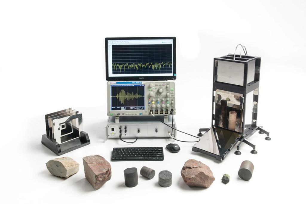


5 Laboratory ADR Core Scanner 5


6 Captured Data System Diagram RCU Trigger Signal TCU Ground Level Time Ground Level Time / depth Time / depth Amplitude Amplitude Rx Antenna Tx Antenna Tablet PC Sub-surface 6
7 Specifications ADR Setting Typical Range Tx frequency maximum 12.5MHz-10GHz Tx frequency minimum 100kHz-1GHz Time Range 2ns to 250,000ns Number of pixels per trace 40 to 4000 Pulse Repetition Frequency (PRF) Pulse Width Power supply Power consumption Power transmission kHz 0.1ns to 10ns 4 off 24Vdc Li-Ion batteries 150W for ADR equipment plus 100W for tablet PC < 5 miliwatts (mw) 7


8 5 Analysis & results Delivery 1 Pre-survey field modelling 2 On-site Survey Data Acquisition 6 Integration to other data sets Training for geological signatures 3 4 Data Processing & Interpretation WE COMBINE EFFICIENT TECHNOLOGY WITH CUSTOMER SERVICE Adrok aims to provide useful subsurface measurements to help de-risk drilling programmes... Thus enhancing recovery of hydrocarbons, minerals & water! 8


9 Types of ADR Scanning in Field (1) WARR Wide Angled Reflection & Refraction Triangulation for conversion of time into depth Tx antenna moves away from stationary Rx Tx moves continuously to say 100m or 300m Rx stays at start of scan line at 0m Rx Antenna Tx Antenna Start - 0m 25m 50m 9
 Note in animation pulse wavelet stays coherent 10")
10 WARR beam forming Line of transmitters in WARR creates beam (Synthetic Aperture Radar, SAR) Note in animation pulse wavelet stays coherent 10
 P-Scan Rx Antenna")


11 Types of ADR Scanning in Field (2) P-Scan Rx Antenna Tx Antenna Start - 0m 25m 50m Antenna Seperation Profile Scan (2-d cross-section) Continuous scanning on the move over short scan line distance (e.g., 50m) Tx & Rx antennas at fixed separation distance (e.g. 0.3m) Typically, 1 pulsed Tx ping every 5cm, repeatedly over entire length of scan line 11

 and whole system stationary Active (Tx on) and")

12 Types of ADR Scanning in Field (3) STARE Rx Antenna Tx Antenna Antenna Seperation Tx & Rx antennas at fixed separation (e.g., 0.3m) and whole system stationary Active (Tx on) and Passive (Tx off) stares gathered to quantify noise levels Stack traces to enhance signal to noise ratio Up to 100,000 traces used in current stack 12

13 Forward Model Maxwell equations coupled to ground model Ground model: permittivity, conductivity and polarization (P) E electric field, σ conductivity, τ Debye relaxation time, ε r dielectric Resulting system of partial differential equations: 13

14 Toolbox of ADR measurements Energy 14


15 Frequency Frequency harmonics Time (ns) H1 H2 H3 H4 H5 H6 H7 H8 H9 H10 H11 H12 H13 H14 H15 H16 H17 H18 H19 H20 H21 H22 H23 H24 H25 H26 H27 H28 H29 H30 H31 H Create image of harmonic energies Establish areas of interest by different resonant frequencies 15


16 Toolbox of ADR measurements Dielectrics Dielectric survey log In this example, from Northern Ireland, high dielectrics verified by client from core inspection to be broken ground, very broken ground or faulting (caused by moisture) 16
 ADR signal depth from Ground Level (m) 1 2 3 4 5")


17 ADR signal depth from Ground Level (m) ADR signal depth from Ground Level (m) ADR signal depth from Ground Level (m) Adrok lithology prognosis Mancal Well Adrok Log of Dielectric Constant against Depth Mancal Well Dielectric log Energy log Mancal Well WMF log 0 0 Adrok Log of Energy against Depth 0 Client log Ad Weighed Mean Frequency aga Basalt Claystone Limestone Dolerite Limestone Claystone Dolerite Claystone Calcareous Mudstone Claystone?


18 18
19 Case Study Nickel exploration under thick permafrost layers in sub-arctic Canada 19

20 20
 Comparison of V-bore data against core hole & other data. Existing core holes with core.")
21 Project Aims & Exploration Challenges (1) Find NiS pods encased within volcanic mafic ultra-mafic rocks to 1000m below ground level through shielding conductors. (2) Comparison of V-bore data against core hole & other data. Existing core holes with core. Undisclosed core holes (blind) (3) Stepping out from the test locations to map the exploration areas of specific interest (prospects) 21
22 Model: Methodology (1) Forward modeling Unfrozen layer of 100m (Resistivity R=5KΩm, Dielectric permittivity ε=8) Permafrost until 1000m (R=200KΩm, ε=5) Liquid water at 1000m (R=1Ωm, ε=40) Stochastic model for irregularities superimposed Permafrost values from: Electrical Resistivity Study of Permafrost on Ridnitšohkka Fell in Northwest Lapland, Finland. Heikki Vanhala, Petri Lintinen and Antti Ojala, Geophysica (2009), 45(1 2), STARE scan with 10X500 traces stacked Show animation of wave in ground Data analysis shows reflector WARR scan 200m wide 40 separations at 10*500 traces each Analysis with dielectric spectrum method 22

23 Animation Top: Electric field from top (left) to bottom Below: Dielectric profile Pulse clearly comes back to surface. 23
24 Model STARE Reflection seen at t=15340ns 24
*15340e-9/2 = 947m.")
25 Model WARR Dielectric can be estimated until about 75000ns at 5.9. Reflection from STARE localized at depth 3e8/sqrt(5.9)*15340e-9/2 = 947m. 5% error. 25
 Existing Core Holes Training hole 1 Correlation peaks seem to correspond to: conductive shield at 430m weak mineralization 516-542m (shown")
26 Blue = mean correlation Red = mean correlation denoised Green = st. deviation Methodology (2) Existing Core Holes Training hole 1 Correlation peaks seem to correspond to: conductive shield at 430m weak mineralization m (shown by the peak in magnetic susceptibility) Pulse appears to propagate through the conductive layer. 26

27 Correlation Key: Blue = mean correlation Red = mean correlation denoised Green = st. deviation GL 1-5MHz 5-10MHz 1600m 1500m training data: spike in conductivity, 430m weak mineralization, m. anomaly in magnetic susceptibility, 525m and 545m 1400m 1300m 1200m 1100m 1000m Training hole 1 Correlation method 27
28 Correlation Key: Blue = mean correlation Red = mean correlation denoised Green = st. deviation GL 1-5MHz 5-10MHz 1600m 1500m training data: spike in conductivity, 430m weak mineralization, m. 1400m 1300m 1200m 1100m anomaly in magnetic susceptibility, 525m and 545m Training Hole m 28

29 Correlation Key: Blue = mean correlation Red = mean correlation denoised Green = st. deviation GL 1-5MHz 5-10MHz 1600m 1500m 1400m training data: weak mineralization m, strong mineralization m, spike in conductivity 610m. 1300m 1200m 1100m 1000m 900m Training hole 2 Correlation method 29
30 (3) Undisclosed holes Spectral Analyses, Correlation, Dielectric spectrum Blind Test WED1 Energy Log example two clear reflectors around 400m deeper reflector at 650m These are confirmed from correlation analysis of W2 and the SWARR (which is assembled by stacking all 21 STARES and collecting in a denoised STARE-WARR. Adrok Ltd
31 Correlation analysis also shows other peaks, some of which correlate with weaker peaks in E-log. The double peak around 400m seems the most prominent feature The m peak is also but seems to be less clear. 31
32 WED1 dielectric spectrum To place reflectors at depth we have to know the pulse propagation velocity, which is determined by the relative permittivity or dielectric constant. This is obtained from what is essentially a triangulation, based on a function of transmitter/receiver separation. Detailed velocity analysis is accurately performed during processing stage quick estimate can be obtained with an appropriately modified version (dielectric spectrum method) of the semblance based velocity spectrum method, commonly used in seismic data analysis. 32
 shows a peak at eps=6, which is the expected value for permafrost.")
33 WED1 dielectric spectrum: Stare WARR Dielectric constant readings are obtained from visually identifying peaks in the (time, eps) false color plot, which correspond to previously identified reflectors. In this case the double reflection peak around 6500ns (400m) shows a peak at eps=6, which is the expected value for permafrost. 33
")
34 Total harmonics, dielectric constant, energy and weighted mean frequency data for Prospect (Thurs1) 34

35 35

36 36

37 37

38 38

39 The two frequency bands for the 1-5MHz and 5-10MHz correlation and standard deviation profiles match up well. I have attached a Geoscience Analyst workspace along with some screen captures from Gocad showing the geology in comparison with the Adrok data. The target in this case was a deep lens of mineralization in the virtual borehole from 717m to 773m. This corresponds with the anomaly seen at the end of the profile from a depth of 722m to 771m. I find the correlation between this anomaly and the mineralized zone to be very encouraging. The correlation anomaly near the centre of the profile (from 550m to 607m) is interesting. It lies in a location that is untested by drilling and is on a horizon that is mineralized in adjacent boreholes. We are currently looking at the BHEM response in this area to further vector targeting. The upper anomaly is drill tested and appears to be a known geological contact. Client feedback Client s integrated ADR virtual borehole results against known drilled results 39
40 Dragging Exploration into the Quantum Age: using Atomic Dielectric Resonance technology to classify sites in the North Atlantic Craton Gordon D.C. Stove CEO & Co-founder
Why electromagnetics have the potential to massively add value to seismic exploration
 Why electromagnetics have the potential to massively add value to seismic exploration Gordon D.C. Stove CEO & Co-founder 9 th March 2017 1 Differences between Seismic and Electromagnetics (EM) 2 What is
Downloaded from library.seg.org by on 10/26/14. For personal use only. SEG Technical Program Expanded Abstracts 2014
 Ground penetrating abilities of broadband pulsed radar in the 1 70MHz range K. van den Doel, Univ. of British Columbia, J. Jansen, Teck Resources Limited, M. Robinson, G. C, Stove, G. D. C. Stove, Adrok
Ground Penetrating Radar (day 1) EOSC Slide 1
 EOSC Slide 1") Ground Penetrating Radar (day 1) Slide 1 Introduction to GPR Today s Topics Setup: Motivational Problems Physical Properties - Dielectric Permittivity and Radiowaves - Microwave Example Basic Principles:
Ground Penetrating Radar (day 1) Slide 1 Introduction to GPR Today s Topics Setup: Motivational Problems Physical Properties - Dielectric Permittivity and Radiowaves - Microwave Example Basic Principles:
7. Consider the following common offset gather collected with GPR.
 Questions: GPR 1. Which of the following statements is incorrect when considering skin depth in GPR a. Skin depth is the distance at which the signal amplitude has decreased by a factor of 1/e b. Skin
Ground Penetrating Radar
 Ground Penetrating Radar Begin a new section: Electromagnetics First EM survey: GPR (Ground Penetrating Radar) Physical Property: Dielectric constant Electrical Permittivity EOSC 350 06 Slide Di-electric
GPR Part II: Effects of conductivity. Surveying geometries. Noise in GPR data. Summary notes with essential equations. Some Case histories
 GPR Part II: Effects of conductivity Surveying geometries Noise in GPR data Summary notes with essential equations Some Case histories EOSC 350 06 Slide 1 GPR Ground Penetrating Radar R = ε ε 2 2 + ε ε
Applied Geophysics Nov 2 and 4
 Applied Geophysics Nov 2 and 4 Effects of conductivity Surveying geometries Noise in GPR data Summary notes with essential equations Some Case histories EOSC 350 06 Slide 1 GPR Ground Penetrating Radar
GPR Investigation: Post Tension Cable Mapping
 CMD Civil Pty Ltd PO Box 1119 Huntingdale VIC 3166 +61 3 9544 8833 info@cmdcivil.com www.cmdcivil.com Case Study: GPR Investigation: Post Tension Cable Mapping This application note demonstrates an example
Results of GPR survey of AGH University of Science and Technology test site (Cracow neighborhood).
.") Results of GPR survey of AGH University of Science and Technology test site (Cracow neighborhood). October 02, 2017 Two GPR sets were used for the survey. First GPR set: low-frequency GPR Loza-N [1]. Technical
Results of GPR survey of AGH University of Science and Technology test site (Cracow neighborhood). October 02, 2017 Two GPR sets were used for the survey. First GPR set: low-frequency GPR Loza-N [1]. Technical
P Forsmark site investigation. RAMAC and BIPS logging in borehole HFM11 and HFM12
 P-04-39 Forsmark site investigation RAMAC and BIPS logging in borehole HFM11 and HFM12 Jaana Gustafsson, Christer Gustafsson Malå Geoscience AB/RAYCON March 2004 Svensk Kärnbränslehantering AB Swedish
GROUND PENETRATING RADAR (GPR)
") Introduction GROUND PENETRATING RADAR (GPR) (After Basson 2000) GPR is an electromagnetic (EM) geophysical method for high-resolution detection, imaging and mapping of subsurface soils and rock conditions.
Introduction GROUND PENETRATING RADAR (GPR) (After Basson 2000) GPR is an electromagnetic (EM) geophysical method for high-resolution detection, imaging and mapping of subsurface soils and rock conditions.
The use of high frequency transducers, MHz, allowing the resolution to target a few cm thick in the first half meter suspect.
 METHODOLOGY GPR (GROUND PROBING RADAR). In recent years the methodology GPR (Ground Probing Radar) has been applied with increasing success under the NDT thanks to the high speed and resolving power. As
Radar Methods General Overview
 Environmental and Exploration Geophysics II Radar Methods General Overview tom.h.wilson tom.wilson@mail.wvu.edu Department of Geology and Geography West Virginia University Morgantown, WV Brown (2004)
Dr. Ali Muqaibel. Associate Professor. Electrical Engineering Department King Fahd University of Petroleum & Minerals Dhahran, Saudi Arabia
 By Associate Professor Electrical Engineering Department King Fahd University of Petroleum & Minerals Dhahran, Saudi Arabia Wednesday, December 1, 14 1 st Saudi Symposium for RADAR Technology 9 1 December
Estimating Debye Parameters from GPR Reflection Data Using Spectral Ratios
 Boise State University ScholarWorks Geosciences Faculty Publications and Presentations Department of Geosciences 9-7-2009 Estimating Debye Parameters from GPR Reflection Data Using Spectral Ratios John
Electromagnetic Induction
 Electromagnetic Induction Recap the motivation for using geophysics We have problems to solve Slide 1 Finding resources Hydrocarbons Minerals Ground Water Geothermal Energy SEG Distinguished Lecture slide
Archaeo-Geophysical Associates, LLC
 Geophysical Survey at the Parker Cemetery Rockwall, Texas. AGA Report 2010-6 Report Submitted To: Texas Cemetery Restoration 10122 Cherry Tree Dr. Dallas, Texas 75243 May 14, 2010 Chester P. Walker, Ph.D.
Geophysical Survey Rock Hill Bleachery TBA Site Rock Hill, South Carolina EP-W EPA, START 3, Region 4 TABLE OF CONTENTS Section Page Signature
 Geophysical Survey Rock Hill Bleachery TBA Site Rock Hill, South Carolina EP-W-05-054 EPA, START 3, Region 4 Prepared for: Tetra Tech EM, Inc. October 12, 2012 Geophysical Survey Rock Hill Bleachery TBA
Ground Penetrating Radar (GPR) By Dr. Eng. Zubair Ahmed
 By Dr. Eng. Zubair Ahmed") Ground Penetrating Radar (GPR) By Dr. Eng. Zubair Ahmed Acknowledgement Golder Associates, Whitby, Ontario Stantec Consulting, Kitchener, Ontario Infrasense Inc. USA Geophysical Survey Systems Inc. (GSSI),
Ground Penetrating Radar (GPR) By Dr. Eng. Zubair Ahmed Acknowledgement Golder Associates, Whitby, Ontario Stantec Consulting, Kitchener, Ontario Infrasense Inc. USA Geophysical Survey Systems Inc. (GSSI),
SIMULATION OF GPR SCENARIOS USING FDTD
 SIMULATION OF GPR SCENARIOS USING FDTD 1 GAMIL ALSHARAHI, 2 ABDELLAH DRIOUACH, 3 AHMED FAIZE 1,2 Department of physic, Abdelmalek Essaâdi University, Faculty of sciences, Morocco 3 Department of physic,
Safety Code 6 (SC6) Measurement Procedures (Uncontrolled Environment)
 Measurement Procedures (Uncontrolled Environment)") February 2011 Spectrum Management and Telecommunications Technical Note Safety Code 6 (SC6) Measurement Procedures (Uncontrolled Environment) Aussi disponible en français NT-329 Contents 1.0 Purpose...1
February 2011 Spectrum Management and Telecommunications Technical Note Safety Code 6 (SC6) Measurement Procedures (Uncontrolled Environment) Aussi disponible en français NT-329 Contents 1.0 Purpose...1
Investigation of Bridge Decks Utilizing Ground Penetrating Radar
 Investigation of Bridge Decks Utilizing Ground Penetrating Radar Steve Cardimona *, Brent Willeford *, John Wenzlick +, Neil Anderson * * The University of Missouri-Rolla, Department of Geology and Geophysics
ATS 351 Lecture 9 Radar
 ATS 351 Lecture 9 Radar Radio Waves Electromagnetic Waves Consist of an electric field and a magnetic field Polarization: describes the orientation of the electric field. 1 Remote Sensing Passive vs Active
3. Electromagnetic methods 3.1 Introduction
 3. Electromagnetic methods 3.1 Introduction The electromagnetic techniques have the broadest range of different instrumental systems. They can be classified as either time domain (TEM) of frequency domain
2015 Interference 101. Robin Jackman Application Engineer
 2015 Interference 101 Robin Jackman Application Engineer Agenda What is Interference Introduction Definitions Spectrum Analyzer Concepts Concepts, Controls, Displays Making good measurements Measuring
Spectral Detection of Attenuation and Lithology
 Spectral Detection of Attenuation and Lithology M S Maklad* Signal Estimation Technology Inc., Calgary, AB, Canada msm@signalestimation.com and J K Dirstein Total Depth Pty Ltd, Perth, Western Australia,
MAKING TRANSIENT ANTENNA MEASUREMENTS
 MAKING TRANSIENT ANTENNA MEASUREMENTS Roger Dygert, Steven R. Nichols MI Technologies, 1125 Satellite Boulevard, Suite 100 Suwanee, GA 30024-4629 ABSTRACT In addition to steady state performance, antennas
Simulating and Testing of Signal Processing Methods for Frequency Stepped Chirp Radar
 Test & Measurement Simulating and Testing of Signal Processing Methods for Frequency Stepped Chirp Radar Modern radar systems serve a broad range of commercial, civil, scientific and military applications.
Earth Observation and Sensing Technologies: a focus on Radar Imaging Developments. Riccardo Lanari
 Earth Observation and Sensing Technologies: a focus on Radar Imaging Developments Riccardo Lanari Institute for Electromagnetic Sensing of the Environment (IREA) National Research Council of Italy (CNR)
Bearing Accuracy Improvement of the Amplitude Comparison Direction Finding Equipment by Analyzing the Error
 80 International Journal of Communication Networks and Information Security (IJCNIS) Bearing Accuracy Improvement of the Amplitude Comparison Direction Finding Equipment by Analyzing the Error Hongsun
THE BEST GPR DATA QUALITY AT THE BEST PRICE! GROUND PENETRATING RADAR ZOND-12e G R O U N D P E N E T R A T I N G R A D A R S
 GROUND PENETRATING RADAR ZOND-12e General Purpose Pulse GPR ZOND-12e SINGLE CHANNEL OR ADVANCED CONTROL UNITS ZOND 12e GPR is a portable digital Ground Penetrating Radar carried by a single operator. The
Detection of Obscured Targets: Signal Processing
 Detection of Obscured Targets: Signal Processing James McClellan and Waymond R. Scott, Jr. School of Electrical and Computer Engineering Georgia Institute of Technology Atlanta, GA 30332-0250 jim.mcclellan@ece.gatech.edu
IMAGING OF DEFECTS IN CONCRETE COMPONENTS WITH NON-CONTACT ULTRASONIC TESTING W. Hillger, DLR and Ing. Büro Dr. Hillger, Braunschweig, Germany
 IMAGING OF DEFECTS IN CONCRETE COMPONENTS WITH NON-CONTACT ULTRASONIC TESTING W. Hillger, DLR and Ing. Büro Dr. Hillger, Braunschweig, Germany Abstract: The building industries require NDT- methods for
Application and signal transmission of the VLF electromagnetic wave in mine rock
 Application and signal transmission of the VLF electromagnetic wave in mine rock Zheng Zhang School of Civil and Environment Engineering, University of Science and Technology Beijing, 100083, China Abstract
Assessment of layer thickness and uniformity in railway embankments with Ground Penetrating Radar
 Assessment of layer thickness and uniformity in railway embankments with Ground Penetrating Radar F.M. Fernandes Department of Civil Engineering, University of Minho, Guimarães, Portugal M. Pereira Geotechnique
Seismic Reflection Method
 1 of 25 4/16/2009 11:41 AM Seismic Reflection Method Top: Monument unveiled in 1971 at Belle Isle (Oklahoma City) on 50th anniversary of first seismic reflection survey by J. C. Karcher. Middle: Two early
Understanding Seismic Amplitudes
 Understanding Seismic Amplitudes The changing amplitude values that define the seismic trace are typically explained using the convolutional model. This model states that trace amplitudes have three controlling
HELICOPTER-BORNE GEOPHYSICAL SURVEY SYSTEMS
 HELICOPTER-BORNE GEOPHYSICAL SURVEY SYSTEMS APPLICATIONS: base & precious metals exploration diamondiferous kimberlite exploration geological mapping mapping of fault zones for engineering and mining applications
Electromagnetic Array Imaging of Steel Bars in Concrete Using High-Speed SAFT
 Malaysia International NDT Conference & Exhibition 215 (MINDTCE-15), Nov 22-24 - www.ndt.net/app.mindtce-15 More Info at Open Access Database www.ndt.net/?id=18659 Electromagnetic Array Imaging of Steel
Prototype Software-based Receiver for Remote Sensing using Reflected GPS Signals. Dinesh Manandhar The University of Tokyo
 Prototype Software-based Receiver for Remote Sensing using Reflected GPS Signals Dinesh Manandhar The University of Tokyo dinesh@qzss.org 1 Contents Background Remote Sensing Capability System Architecture
Effect of Frequency and Migration Aperture on Seismic Diffraction Imaging
 IOP Conference Series: Earth and Environmental Science PAPER OPEN ACCESS Effect of Frequency and Migration Aperture on Seismic Diffraction Imaging To cite this article: Y. Bashir et al 2016 IOP Conf. Ser.:
Enhanced low frequency signal processing for sub-basalt imaging N. Woodburn*, A. Hardwick and T. Travis, TGS
 Enhanced low frequency signal processing for sub-basalt imaging N. Woodburn*, A. Hardwick and T. Travis, TGS Summary Sub-basalt imaging continues to provide a challenge along the northwest European Atlantic
Innovative Solutions Across the E&P Lifecycle. ACCESS EXPLORATION APPRAISAL DEVELOPMENT PRODUCTION
 Innovative Solutions Across the E&P Lifecycle. ACCESS EXPLORATION APPRAISAL DEVELOPMENT PRODUCTION Innovative Solutions, from Access to Production Uncertainty Knowledge ACCESS EXPLORATION APPRAISAL DEVELOPMENT
A COMPARISON OF ELECTRODE ARRAYS IN IP SURVEYING
 A COMPARISON OF ELECTRODE ARRAYS IN IP SURVEYING John S. Sumner Professor of Geophysics Laboratory of Geophysics and College of Mines University of Arizona Tucson, Arizona This paper is to be presented
Advanced Ground Investigation Techniques to Help Limit Risk or Examine Failure. Advanced Subsurface Investigations
 Advanced Ground Investigation Techniques to Help Limit Risk or Examine Failure Overview Introduction What is geophysics? Why use it? Common Methods Seismic Ground Radar Electrical Case Studies Conclusion
Principles of Pulse-Doppler Radar p. 1 Types of Doppler Radar p. 1 Definitions p. 5 Doppler Shift p. 5 Translation to Zero Intermediate Frequency p.
 Preface p. xv Principles of Pulse-Doppler Radar p. 1 Types of Doppler Radar p. 1 Definitions p. 5 Doppler Shift p. 5 Translation to Zero Intermediate Frequency p. 6 Doppler Ambiguities and Blind Speeds
Theoretical Approach. Why do we need ultra short technology?? INTRODUCTION:
 Theoretical Approach Why do we need ultra short technology?? INTRODUCTION: Generating ultrashort laser pulses that last a few femtoseconds is a highly active area of research that is finding applications
GPR Data Acquisition and Interpretation
 1 GPR Data Acquisition and Interpretation Mezgeen Rasol PhD Candidate Geophysics and Seismic Engineering Polytechnic University of Catalonia mezgeen.rasol@upc.edu BIG-SKY-EARTH Cost Action TD143 Workshop
GPR SURVEY METHOD. Ground probing radar
 The ground penetrating radar (GPR - Ground Probing Radar) is a geophysical method used to investigate the near surface underground. Thanks to its high degree of resolution, the GPR is the most effective
PERFORMANCE CONSIDERATIONS FOR PULSED ANTENNA MEASUREMENTS
 PERFORMANCE CONSIDERATIONS FOR PULSED ANTENNA MEASUREMENTS David S. Fooshe Nearfield Systems Inc., 19730 Magellan Drive Torrance, CA 90502 USA ABSTRACT Previous AMTA papers have discussed pulsed antenna
EC ANTENNA AND WAVE PROPAGATION
 EC6602 - ANTENNA AND WAVE PROPAGATION FUNDAMENTALS PART-B QUESTION BANK UNIT 1 1. Define the following parameters w.r.t antenna: i. Radiation resistance. ii. Beam area. iii. Radiation intensity. iv. Directivity.
ECE 476/ECE 501C/CS Wireless Communication Systems Winter Lecture 6: Fading
 ECE 476/ECE 501C/CS 513 - Wireless Communication Systems Winter 2003 Lecture 6: Fading Last lecture: Large scale propagation properties of wireless systems - slowly varying properties that depend primarily
Variable-depth streamer acquisition: broadband data for imaging and inversion
 P-246 Variable-depth streamer acquisition: broadband data for imaging and inversion Robert Soubaras, Yves Lafet and Carl Notfors*, CGGVeritas Summary This paper revisits the problem of receiver deghosting,
ECE 476/ECE 501C/CS Wireless Communication Systems Winter Lecture 6: Fading
 ECE 476/ECE 501C/CS 513 - Wireless Communication Systems Winter 2004 Lecture 6: Fading Last lecture: Large scale propagation properties of wireless systems - slowly varying properties that depend primarily
ECE 476/ECE 501C/CS Wireless Communication Systems Winter Lecture 6: Fading
 ECE 476/ECE 501C/CS 513 - Wireless Communication Systems Winter 2005 Lecture 6: Fading Last lecture: Large scale propagation properties of wireless systems - slowly varying properties that depend primarily
WS01 B02 The Impact of Broadband Wavelets on Thin Bed Reservoir Characterisation
 WS01 B02 The Impact of Broadband Wavelets on Thin Bed Reservoir Characterisation E. Zabihi Naeini* (Ikon Science), M. Sams (Ikon Science) & K. Waters (Ikon Science) SUMMARY Broadband re-processed seismic
Microwave Remote Sensing
 Provide copy on a CD of the UCAR multi-media tutorial to all in class. Assign Ch-7 and Ch-9 (for two weeks) as reading material for this class. HW#4 (Due in two weeks) Problems 1,2,3 and 4 (Chapter 7)
Specification. Patent Pending. Description : AccuraUWB Flex Series 3~10GHz Ultra-Wide Band (UWB) Flex Antenna with 100mm 1.
 Flex Antenna with 100mm 1.") Specification Patent Pending Part No. : FXUWB10.07.0100C Description : AccuraUWB Flex Series 3~10GHz Ultra-Wide Band (UWB) Flex Antenna with 100mm 1.37mm IPEX MHFHT Features : Flexible UWB Antenna Mounting
Specification Patent Pending Part No. : FXUWB10.07.0100C Description : AccuraUWB Flex Series 3~10GHz Ultra-Wide Band (UWB) Flex Antenna with 100mm 1.37mm IPEX MHFHT Features : Flexible UWB Antenna Mounting
Scalable Ionospheric Analyser SIA 24/6
 Scalable Ionospheric Analyser SIA 24/6 Technical Overview Functional description The ATRAD Scalable Ionospheric Analyser SIA24/6 is designed to observe ionospheric irregularities and their drift in the
GPR SYSTEM USER GUIDE AND TROUBLESHOOTING GUIDE
 GPR SYSTEM USER GUIDE AND TROUBLESHOOTING GUIDE Implementation Report 5-4414-01-1 Project Number 5-4414-01 Subsurface Sensing Lab Electrical and Computer Engineering University of Houston 4800 Calhoun
General MIMO Framework for Multipath Exploitation in Through-the-Wall Radar Imaging
 General MIMO Framework for Multipath Exploitation in Through-the-Wall Radar Imaging Michael Leigsnering, Technische Universität Darmstadt Fauzia Ahmad, Villanova University Moeness G. Amin, Villanova University
System configurations. Main features. I TScan SOLUTION FOR
 TScan TScan is a fast and ultra-accurate planar near-field scanner with the latest motor drive and encoder technologies. High acceleration of the linear motors for stepped and continuous mode operation
Development and Application of 500MSPS Digitizer for High Resolution Ultrasonic Measurements
 Indian Society for Non-Destructive Testing Hyderabad Chapter Proc. National Seminar on Non-Destructive Evaluation Dec. 7-9, 2006, Hyderabad Development and Application of 500MSPS Digitizer for High Resolution
The Measurement and Characterisation of Ultra Wide-Band (UWB) Intentionally Radiated Signals
 Intentionally Radiated Signals") The Measurement and Characterisation of Ultra Wide-Band (UWB) Intentionally Radiated Signals Rafael Cepeda Toshiba Research Europe Ltd University of Bristol November 2007 Rafael.cepeda@toshiba-trel.com
The Measurement and Characterisation of Ultra Wide-Band (UWB) Intentionally Radiated Signals Rafael Cepeda Toshiba Research Europe Ltd University of Bristol November 2007 Rafael.cepeda@toshiba-trel.com
Fundamental Concepts of Radar
 Fundamental Concepts of Radar Dr Clive Alabaster & Dr Evan Hughes White Horse Radar Limited Contents Basic concepts of radar Detection Performance Target parameters measurable by a radar Primary/secondary
Interpretational applications of spectral decomposition in reservoir characterization
 Interpretational applications of spectral decomposition in reservoir characterization GREG PARTYKA, JAMES GRIDLEY, and JOHN LOPEZ, Amoco E&P Technology Group, Tulsa, Oklahoma, U.S. Figure 1. Thin-bed spectral
Radar Imaging of Concealed Targets
 Radar Imaging of Concealed Targets Vidya H A Department of Computer Science and Engineering, Visveswaraiah Technological University Assistant Professor, Channabasaveshwara Institute of Technology, Gubbi,
The Radio Channel. COS 463: Wireless Networks Lecture 14 Kyle Jamieson. [Parts adapted from I. Darwazeh, A. Goldsmith, T. Rappaport, P.
 The Radio Channel COS 463: Wireless Networks Lecture 14 Kyle Jamieson [Parts adapted from I. Darwazeh, A. Goldsmith, T. Rappaport, P. Steenkiste] Motivation The radio channel is what limits most radio
Nuove tecnologie per ecografia ad ultrasuoni: da 2D a 4D
 DINFO Dipartimento di Ingegneria dell Informazione Department of Information Engineering Nuove tecnologie per ecografia ad ultrasuoni: da 2D a 4D Piero Tortoli Microelectronics Systems Design Lab 1 Introduction
Development and Field Testing of a Seismic System for Locating Trapped Miners - Progress Report. Yi Luo, Keith A. Heasley and Syd S.
 Development and Field Testing of a Seismic System for Locating Trapped Miners - Progress Report Yi Luo, Keith A. Heasley and Syd S. Peng Department of Mining Engineering West Virginia University Acknowledgements
The application of GPR for the modeling of ERT data and the evaluation of resolution for different electrode configurations
 BACHELOR THESIS The application of GPR for the modeling of ERT data and the evaluation of resolution for different TU Wien Department of Geodesy and Geoinformation Research Group Geophysics Performed by
Small-Scale Fading I PROF. MICHAEL TSAI 2011/10/27
 Small-Scale Fading I PROF. MICHAEL TSAI 011/10/7 Multipath Propagation RX just sums up all Multi Path Component (MPC). Multipath Channel Impulse Response An example of the time-varying discrete-time impulse
RANGE resolution and dynamic range are the most important
 INTL JOURNAL OF ELECTRONICS AND TELECOMMUNICATIONS, 2012, VOL. 58, NO. 2, PP. 135 140 Manuscript received August 17, 2011; revised May, 2012. DOI: 10.2478/v10177-012-0019-1 High Resolution Noise Radar
Electromagnetic Logging Technique Based on Borehole Radar
 IEEE TRANSACTIONS ON GEOSCIENCE AND REMOTE SENSING, VOL. 40, NO. 9, SEPTEMBER 2002 2083 Electromagnetic Logging Technique Based on Borehole Radar Sixin Liu and Motoyuki Sato, Senior Member, IEEE Abstract
Rec. ITU-R P RECOMMENDATION ITU-R P *
 Rec. ITU-R P.682-1 1 RECOMMENDATION ITU-R P.682-1 * PROPAGATION DATA REQUIRED FOR THE DESIGN OF EARTH-SPACE AERONAUTICAL MOBILE TELECOMMUNICATION SYSTEMS (Question ITU-R 207/3) Rec. 682-1 (1990-1992) The
Antennas and Propagation
 Antennas and Propagation Chapter 5 Introduction An antenna is an electrical conductor or system of conductors Transmission - radiates electromagnetic energy into space Reception - collects electromagnetic
Report. Mearns Consulting LLC. Former Gas Station 237 E. Las Tunas Drive San Gabriel, California Project # E
 Mearns Consulting LLC Report Former Gas Station 237 E. Las Tunas Drive San Gabriel, California Project #1705261E Charles Carter California Professional Geophysicist 20434 Corisco Street Chatsworth, CA
VALIDATION OF GROUND PENETRATING RADAR DATA INTERPRETATION USING AN ELECTROMAGNETIC WAVE PROPAGATION SIMULATOR
 Romanian Reports in Physics, Vol. 68, No. 4, P. 1584 1588, 2016 VALIDATION OF GROUND PENETRATING RADAR DATA INTERPRETATION USING AN ELECTROMAGNETIC WAVE PROPAGATION SIMULATOR A. CHELMUS National Institute
Vol. 58 No. 7. July MVP NI AWR Design Environment. Founded in 1958
 Vol. 58 No. 7 July 215.com MVP NI AWR Design Environment Founded in 1958 98 MICROWAVE JOURNAL JULY 215 Managing Circuit Materials at mmwave Frequencies John Coonrod Rogers Corp., Chandler, Ariz. This article
MOBILE RAPID-SCANNING X-BAND POLARIMETRIC (RaXPol) DOPPLER RADAR SYSTEM Andrew L. Pazmany 1 * and Howard B. Bluestein 2
 DOPPLER RADAR SYSTEM Andrew L. Pazmany 1 * and Howard B. Bluestein 2") 16B.2 MOBILE RAPID-SCANNING X-BAND POLARIMETRIC (RaXPol) DOPPLER RADAR SYSTEM Andrew L. Pazmany 1 * and Howard B. Bluestein 2 1 ProSensing Inc., Amherst, Massachusetts 2 University of Oklahoma, Norman,
16B.2 MOBILE RAPID-SCANNING X-BAND POLARIMETRIC (RaXPol) DOPPLER RADAR SYSTEM Andrew L. Pazmany 1 * and Howard B. Bluestein 2 1 ProSensing Inc., Amherst, Massachusetts 2 University of Oklahoma, Norman,
Switched Mode Power Supply Measurements
 Power Analysis 1 Switched Mode Power Supply Measurements AC Input Power measurements Safe operating area Harmonics and compliance Efficiency Switching Transistor Losses Measurement challenges Transformer
Automotive 77GHz; Coupled 3D-EM / Asymptotic Simulations. Franz Hirtenfelder CST /AG
 Automotive Radar @ 77GHz; Coupled 3D-EM / Asymptotic Simulations Franz Hirtenfelder CST /AG Abstract Active safety systems play a major role in reducing traffic fatalities, including adaptive cruise control,
GPR ANTENNA ARRAY FOR THE INSPECTION OF RAILWAY BALLAST
 Proceedings of the National Seminar & Exhibition on Non-Destructive Evaluation NDE 2011, December 8-10, 2011 GPR ANTENNA ARRAY FOR THE INSPECTION OF RAILWAY BALLAST Th. Kind BAM Federal Institute for Materials
SUPPLEMENTARY INFORMATION
 Optically reconfigurable metasurfaces and photonic devices based on phase change materials S1: Schematic diagram of the experimental setup. A Ti-Sapphire femtosecond laser (Coherent Chameleon Vision S)
Propagation Mechanism
 Propagation Mechanism ELE 492 FUNDAMENTALS OF WIRELESS COMMUNICATIONS 1 Propagation Mechanism Simplest propagation channel is the free space: Tx free space Rx In a more realistic scenario, there may be
Design of an Optimal High Pass Filter in Frequency Wave Number (F-K) Space for Suppressing Dispersive Ground Roll Noise from Onshore Seismic Data
 Space for Suppressing Dispersive Ground Roll Noise from Onshore Seismic Data") Universal Journal of Physics and Application 11(5): 144-149, 2017 DOI: 10.13189/ujpa.2017.110502 http://www.hrpub.org Design of an Optimal High Pass Filter in Frequency Wave Number (F-K) Space for Suppressing
Universal Journal of Physics and Application 11(5): 144-149, 2017 DOI: 10.13189/ujpa.2017.110502 http://www.hrpub.org Design of an Optimal High Pass Filter in Frequency Wave Number (F-K) Space for Suppressing
Analysis of Crack Detection in Metallic and Non-metallic Surfaces Using FDTD Method
 ECNDT 26 - We.4.3.2 Analysis of Crack Detection in Metallic and Non-metallic Surfaces Using FDTD Method Faezeh Sh.A.GHASEMI 1,2, M. S. ABRISHAMIAN 1, A. MOVAFEGHI 2 1 K. N. Toosi University of Technology,
Multi-Sensor Measurements for the Detection of Buried Targets
 Multi-Sensor Measurements for the Detection of Buried Targets Waymond R. Scott, Jr. and James McClellan School of Electrical and Computer Engineering Georgia Institute of Technology Atlanta, GA 333 waymond.scott@ece.gatech.edu
Lecture 9. Radar Equation. Dr. Aamer Iqbal. Radar Signal Processing Dr. Aamer Iqbal Bhatti
 Lecture 9 Radar Equation Dr. Aamer Iqbal 1 ystem Losses: Losses within the radar system itself are from many sources. everal are described below. L PL =the plumbing loss. L PO =the polarization loss. L
Set No.1. Code No: R
 Set No.1 IV B.Tech. I Semester Regular Examinations, November -2008 RADAR SYSTEMS ( Common to Electronics & Communication Engineering and Electronics & Telematics) Time: 3 hours Max Marks: 80 Answer any
Bayesian Estimation of Tumours in Breasts Using Microwave Imaging
 Bayesian Estimation of Tumours in Breasts Using Microwave Imaging Aleksandar Jeremic 1, Elham Khosrowshahli 2 1 Department of Electrical & Computer Engineering McMaster University, Hamilton, ON, Canada
Statement of Qualifications
 Revised January 29, 2011 ClearView Geophysics Inc. 12 Twisted Oak Street Brampton, ON L6R 1T1 Canada Phone: (905) 458-1883 Fax: (905) 792-1884 general@geophysics.ca www.geophysics.ca 1 1. Introduction
Lecture 6 SIGNAL PROCESSING. Radar Signal Processing Dr. Aamer Iqbal Bhatti. Dr. Aamer Iqbal Bhatti
 Lecture 6 SIGNAL PROCESSING Signal Reception Receiver Bandwidth Pulse Shape Power Relation Beam Width Pulse Repetition Frequency Antenna Gain Radar Cross Section of Target. Signal-to-noise ratio Receiver
Annex 5. Determination of the interference field strength in the Land Mobile Service
 Annex 5 Determination of the interference field strength in the Land Mobile Service Annex 5, page 2 of 18 1 General 1.1 This calculation method is based on Recommendation ITU-R P.1546, taking into account
GCM mapping Vildbjerg - HydroGeophysics Group - Aarhus University
 GCM mapping Vildbjerg - HydroGeophysics Group - Aarhus University GCM mapping Vildbjerg Report number 06-06-2017, June 2017 Indholdsfortegnelse 1. Project information... 2 2. DUALEM-421s... 3 2.1 Setup
RECOMMENDATION ITU-R S.1341*
 Rec. ITU-R S.1341 1 RECOMMENDATION ITU-R S.1341* SHARING BETWEEN FEEDER LINKS FOR THE MOBILE-SATELLITE SERVICE AND THE AERONAUTICAL RADIONAVIGATION SERVICE IN THE SPACE-TO-EARTH DIRECTION IN THE BAND 15.4-15.7
Boost Your Skills with On-Site Courses Tailored to Your Needs
 Boost Your Skills with On-Site Courses Tailored to Your Needs www.aticourses.com The Applied Technology Institute specializes in training programs for technical professionals. Our courses keep you current
Survey results obtained in a complex geological environment with Midwater Stationary Cable Luc Haumonté*, Kietta; Weizhong Wang, Geotomo
 Survey results obtained in a complex geological environment with Midwater Stationary Cable Luc Haumonté*, Kietta; Weizhong Wang, Geotomo Summary A survey with a novel acquisition technique was acquired
Who We Are. Antennas Space Terahertz
 Anteral Products Who We Are Anteral was born in 2011 as a spin-off of the Public University of Navarra (UPNA) Antenna Group. It is a technological company with an innovative profile. Anteral is focused
PEOPLE PROCESS EQUIPMENT TECHNOLOGY VALUE. Cased-Hole Services Optimize Your Well Production
 PEOPLE PROCESS EQUIPMENT TECHNOLOGY VALUE Cased-Hole Services Optimize Your Well Production Optimize Your Well Production Allied-Horizontal s complete portfolio of reservoir evaluation and completion services