2015 Interference 101. Robin Jackman Application Engineer
|
|
|
- Reynold Murphy
- 5 years ago
- Views:
Transcription


1 2015 Interference 101 Robin Jackman Application Engineer
2 Agenda What is Interference Introduction Definitions Spectrum Analyzer Concepts Concepts, Controls, Displays Making good measurements Measuring & Locating Interference Basic Direction Finding Techniques Logging Data Review On-Line Resources 2
3 What Is Interference There are a number of problems that indicate interference Adequate signal, poor reception Adequate signal, no access? No Signal? Interference = Degraded System Performance
4 Is It Really Interference? Understand system level issues Situational awareness what is happening around us 4
5 Suspecting Interference? Impaired signal at mobile? Impaired signal at base station? Where Is The Victim Receiver? 5
6 RSSI Rx Channel Understanding Interference Receiver pre-selector rejects out-of-band RF at input Narrow Bandwidth desired to reject out of channel signals Low Loss desired to allow sensitivity Rx Band Frequency/Channel 6
7 RSSI Interference Rx Channel Receiver De-Sensitization Signals passed by the pre-selector cause a reduction in the gain of the receiver amplifier. Rx is less sensitive, loss of coverage area Rx Band Frequency/Channel 7
8 RSSI Interference Rx Channel Receiver Blocking Strong signals passed by the pre-selector cause the receiver amplifier to go into compression. System is un-usable ie: Co-Channel or Adjacent Channels Rx Band Frequency/Channel 8
9 Fundamental Interference Fundamental interference is when two transmissions are at the same frequency Co-channel frequency assignments Some systems have fundamental interference since all sites use same frequencies. Tx coding reduces the effects Primary cause of cell capacity limitations. It is managed by careful power control 9

10 10 Fundamental Interference Generally speaking frequencies are always re-used, just not in local area. Hills combined with antenna aiming issues can allow coverage areas to overlap. Ionospheric variables = Long range interference
11 Intermodulation Interference Transmitter Involvement An external signal can back feed into a transmitter via the transmit antenna. Transmitters have diodes and transistors Antennas receive as well as transmit Other signals may enter a transmitter via the transmitter s antenna VERY common problem Transmitter 1 Transmitter 2 11
12 Intermodulation Interference Non-linear devices are found in: Diodes Transistors (amplifiers) Multi-couplers Cables Connectors Rust and corrosion Almost anywhere! PIM Tested? VHF PIM? Filters (Traps) often required 12

13 ~ Interference Intermodulation Interference - 3 Rd Order Intermodulation = 2F1 F2 - Most Common Rx Band Tx Band Pager F1 Harmonic 835 MHz 2F1 - F2 883 MHz F1 931 MHz F MHz 2 x F1 13
14 So Which Carriers Can Cause Problems? Mixing Product Calculator Enter F1 and F2 to operate F F F F F F2 2 F2 3 F2 4 F2 5 F
15 What Tools Do I Need? Protocol based tool will tell us our QOS is being impacted, it doesn t tell us WHAT is impacting the system Spectrum analyzers are the go to tool for looking at RF issues Spectrum analyzer categories Swept Low Probability of Intercept Real Time High Probability Of Intercept How long does a signal have to be on to guarantee intercept? 15
16 Agenda What is Interference Introduction Definitions Spectrum Analyzer Concepts Concepts, Controls, Displays Making good measurements Measuring & Locating Interference Basic Direction Finding Techniques Logging Data Review On-Line Resources 16
17 Amplitude Overview Spectrum Analyzer Display A 3 A 1 A 2 f 1 f 2 f 3 Frequency 17

18 Overview Traditional Spectrum Analyzer Block Diagram Frequency RBW # Trace Points Detector Type Span Ref Level Sweep Speed VBW 18
19 Overview Basic Spectrum Analyzer Controls Start Freq Stop Freq 19 Center Freq
20 Overview Basic Spectrum Analyzer Controls Reference Level 20
21 Overview Logarithmic Scaling To display very large and very small signals on the same screen, the spectrum analyzer uses a logarithmic scale based on the decibel. db = 10 log (P/ Pref) -40 dbm = mw -30 dbm = mw -20 dbm = 0.01 mw -10 dbm = 0.1 mw -3dBm = 0.5 mw 0 dbm = 1 mw 3 dbm = 2 mw 10 dbm = 10 mw 20 dbm = 100 mw 30 dbm = 1,000 mw 40 dbm = 10,000 mw When power doubles or halves, it changes by 3dB 21
22 Overview Basic Spectrum Analyzer Controls Resolution Bandwidth Control 22
23 Overview Resolution - RBW Filter level level level freq freq freq Wide Faster RBW Speed Narrow Slower

24 Overview Traditional Spectrum Display Detector RBW Limits # Trace Points POI = ms See Less 24

25 Overview Real Time Spectrum Analyzer Block Diagram Frequency RBW # Trace Points Detector Type Span Ref Level Acquisition Time VBW 25

26 Overview Real Time Spectrum Display Persistence 10,000 FFT/s POI = 100uS See More 26


27 Overview DPX Color Palettes & Color Scales Max. = 100%, Min. = 0% Max. < 100% Min. > 0% Color = How Often The Signal Is Present Adjust Mapping of Pixel Occurrences to Color Raising The Minimum Hides The Infrequent Lowering The Max. Emphasizes The Average 27


28 Overview DPX Versus Max Hold Conventional Spectrum Analyzer Display DPX Spectral Display Max. Hold Trace Infinite Persistence DPX Carrier Leakage Sweeping Trace 28

29 Overview Spectrogram The spectrogram shows how an RF signal changes over time It s basically a strip chart recorder for the spectrum information
30 Overview Swept Tuned vs. Real-Time Swept Analyzers Real-Time Analyzer Span = 40M RBW = 1 MHz 801 pts Span = 40 MHz RBW = 300kHz 801 pts 40ms 4629 Frames 2ms + 18ms = 20ms 18ms 2314 Frames 2ms Retrace + Process Time Frequency Frequency 112 MS/s 1 Frame = 8.64us

31 Overview Spectrogram Record your spectrum for long periods of time Playback problem periods

32 LAB Time! Lab Exercise #1 Monitor FM Broadcast Frequency Span Amplitude Reference Level Multiple Measurements
 Optional Commercial")


33 SignalVu-PC Benchtop Spectrum Analyzer features Optional Vector Signal Analysis (40 MHz Demod BW) Optional Commercial Wireless features like Wi-Fi, Bluetooth, P25 Mapping of multiple measurements for geolocation of signals Standard Real-Time Spectrum Analysis Real Time display showing WLAN signal Vector Signal Analysis of a QPSK signal FM signal analysis: DPX, Spectrogram, Freq. vs Time Wi-Fi Signal Analysis Mapping of signals to locate an interfering signal Signal Strength and Spectrogram
34 Agenda What is Interference Introduction Definitions Spectrum Analyzer Concepts Concepts, Controls, Displays Making good measurements Measuring & Locating Interference Basic Direction Finding Techniques Logging Data Review On-Line Resources 34
 Modulation Spectrum Shape System Level Issues")
35 Measuring & Locating Interference Frequency Band Plan(s) Modulation Spectrum Shape System Level Issues Sound 35

36 Receiver Interference Spotting Hookup If interference is severe Disable traffic on that sector or channel Hookup an instrument receive antenna Make measurements This is the preferred measurement solution: it s faster If interference allows traffic to continue Hookup to redundant receive antenna Wait for traffic to slow down to make measurements Not the preferred measuring solution: it s slower 36 March 15
37 Rx Splitters Hookup Locations Location A Watch Out for DC Power! Location B and D Likely more sensitive than C Location C What the radio sees Easy to spot any BTS fault Less sensitive than B or D Diversity Antenna Rx 2 only Mast Mounted Preamp? Preselector & Power Insertion Rx Splitter 1 N Rx 1 A B Duplexer/Splitter Main Antenna Rx 1 Path Shown C Radio D Rx 2 To/From Switch 37 March 15

38 Logging Data: Spectrogram Log signal activity Remotely Long time periods When & how often is problem happening? 38

39 Logging Data: Action On Trigger User Defined Mask helps when staring in a span Mask Violation DPX Trace Combination DPX and Mask Test Actions on trigger: screen shot, record RF,

40 Logging Data: Basic Drive Testing 6 measurements can be measured and mapped automatically 40

41 Logging Data: Basic Drive Testing Log files can be mapped with simple, low cost software Mapping Received Signal Strength Indication aka channel power 41
42 Logging Data: Signal Parameters Frequency Occupied Bandwidth Crest Factor What Does It Sound Like? 42
43 Triangulation (Theory) To locate a signal need at least 2 good measurements We need to correlate signal strength Collect measurements from multiple locations Basic understanding of antenna patterns Keep Moving 43
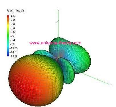

44 Triangulation: Antenna Types Directional Antenna 44

45 Triangulation: Antenna Types Simple Dipole can be very effective Use NULL of antenna to locate weak or no signal Inverse Tone Use body as shield Add attenuation to reduce the effects of ambient signals 45

46 Triangulation: Target Zone Visible Source? Map and Compass Beware of reflections Beware F/B Ratio Beware of antenna pattern Beware of POI More LOB s the better! Area of Uncertainty 46 March 15


47 Triangulation: Antenna Types Once inside the target zone switch to monopole or nearfield antenna Use body as shield Add attenuation to reduce the effects of ambient signals 47

48 LAB Time! Lab Exercise #2 Monitor Wifi/Bluetooth DPX/DPX Ogram Masks Triggering eguide To Signals More Examples Download yourself
49 Agenda What is Interference Introduction Definitions Spectrum Analyzer Concepts Concepts, Controls, Displays Making good measurements Measuring & Locating Interference Basic Direction Finding Techniques Remote Monitoring Logging Data Review On-Line Resources 49

50 Interference 101 Understand your system Understand your spectrum Understand your interference Spectrum signature? How often is it occurring? Where is it coming from? What does it sound like? 50

51 Additional Resources Good Starting Location Interference Types Advice Lot s of Information

52 Additional Resources Search for licensed operators Spectrum frequency lists Lot s of information Technical Administrative Frequency List

53 Additional Resources Spectrum Tektronix Videos eguide to Signals
54 Additional Resources Radio standards Info Transmission Theory Antenna theory transition.fcc.gov/cgb/consumerfacts/interference.pdf FCC Interference Industry Canada Interference 54


55 55
Understanding RF and Microwave Analysis Basics
 Understanding RF and Microwave Analysis Basics Kimberly Cassacia Product Line Brand Manager Keysight Technologies Agenda µw Analysis Basics Page 2 RF Signal Analyzer Overview & Basic Settings Overview
Utilizzo del Time Domain per misure EMI
 Utilizzo del Time Domain per misure EMI Roberto Sacchi Measurement Expert Manager - Europe 7 Giugno 2017 Compliance EMI receiver requirements (CISPR 16-1-1 ) range 9 khz - 18 GHz: A normal +/- 2 db absolute
RF Fundamentals Part 2 Spectral Analysis
 Spectral Analysis Dec 8, 2016 Kevin Nguyen Keysight Technologies Agenda Overview Theory of Operation Traditional Spectrum Analyzers Modern Signal Analyzers Specifications Features Wrap-up Page 2 Overview
Appnote - Realtime Spectrum Analyzer vs Spectrum Analyzer
 Appnote - Realtime Spectrum Analyzer vs Spectrum Analyzer Today the RF industry has to face more and more the open question, how to transport the data from my test device (DUT) to different receiver spots
Interference Analysis and Spectrum Monitor Seminar
 Interference Analysis and Spectrum Monitor Seminar Handheld RF & Microwave Instruments Andrew Benn Business Development Manager Agilent Technologies Wednesday 12 th October 2011 1 Agilent Technologies,
LTE Signal Quality Analysis. BTS Master, Cell Master,, Spectrum Master
 LTE Signal Quality Analysis BTS Master, Cell Master,, Spectrum Master Slide 1 Anritsu LTE Test Instrument Portfolio Signaling Tester Fading Simulator Signal Analyzers Vector Signal Generator Radio Communication
JD746A/JD786A CellAdvisor RF Analyzer
 JD746A/JD786A CellAdvisor RF Analyzer JD746A JD786A Spectrum Analyzer: 100 khz to 4 GHz 9 khz to 8 GHz Cable and Antenna Analyzer: 5 MHz to 4 GHz 5 MHz to 6 GHz RF Power Meter: 10 MHz to 4 GHz 10 MHz to
Signal Leakage Patrolling in the 700 MHz Frequency Band
 Signal Leakage Patrolling in the 700 MHz Frequency Band Welcome to the 1 st Quarter 2013 CSEI Technical Report. My last technical report, in the 2 nd Qtr of 2012 (the 3 rd & 4 th quarters of 2012 were
3250 Series Spectrum Analyzer
 The most important thing we build is trust ADVANCED ELECTRONIC SOLUTIONS AVIATION SERVICES COMMUNICATIONS AND CONNECTIVITY MISSION SYSTEMS 3250 Series Spectrum Analyzer > Agenda Introduction
Interference Direction Analysis. Communication Signals
 1 PLC Power Line Communications I/Q Analyzer-Magnitude: The display here captures the entire signal in the time domain over a bandwidth of almost 27 MHz, making precise triggering easier. I/Q Analyzer-HiRes
Understanding Probability of Intercept for Intermittent Signals
 2013 Understanding Probability of Intercept for Intermittent Signals Richard Overdorf & Rob Bordow Agilent Technologies Agenda Use Cases and Signals Time domain vs. Frequency Domain Probability of Intercept
Measuring ACPR of W-CDMA signals with a spectrum analyzer
 Measuring ACPR of W-CDMA signals with a spectrum analyzer When measuring power in the adjacent channels of a W-CDMA signal, requirements for the dynamic range of a spectrum analyzer are very challenging.
Spectrum Analyzers 2680 Series Features & benefits
 Data Sheet Features & benefits n Frequency range: 9 khz to 2.1 or 3.2 GHz n High Sensitivity -161 dbm/hz displayed average noise level (DANL) n Low phase noise of -98 dbc/hz @ 10 khz offset n Low level
EMI 相容性測試 預相容性測試及量測法規
 EMI 相容性測試 預相容性測試及量測法規 12/13/2016 太克科技 Laurance Yeh 葉志豪 chi-hao.yeh@tektronix.com Agenda EMI introduction EMI pre-compliance and debugging tools RSA306B demo MDO4000C demo lab 13 December 2016 Agenda EMI
DSA-815 Demo Guide. Solution: The DSA 800 series of spectrum analyzers are packed with features.
 FAQ Instrument Solution FAQ Solution Title DSA-815 Demo Guide Date:08.29.2012 Solution: The DSA 800 series of spectrum analyzers are packed with features. Spectrum analyzers are similar to oscilloscopes..
The LoRa Protocol. Overview. Interference Immunity. Technical Brief AN205 Rev A0
 Technical Brief AN205 Rev A0 The LoRa Protocol By John Sonnenberg Raveon Technologies Corp Overview The LoRa (short for Long Range) modulation scheme is a modulation technique combined with a data encoding
Handheld Spectrum Analyzer. SpecMini. Transcom Instruments.
 Handheld Spectrum Analyzer SpecMini Transcom Instruments www.transcomwireless.com Content Overview of SpecMini Spectrum Analyzer Basic Overview Product Features Applications Technical Specifications Operating
Dive deep into interference analysis
 Dive deep into interference analysis Dive deep into interference analysis Contents 1. Introducing Narda Outstanding features 2. Basics IDA 2 3. IDA 2 presentation How IDA 2 is used: 1) Detect 2) Analyze
NXDN Signal and Interference Contour Requirements An Empirical Study
 NXDN Signal and Interference Contour Requirements An Empirical Study Icom America Engineering December 2007 Contents Introduction Results Analysis Appendix A. Test Equipment Appendix B. Test Methodology
Trouble-shooting Radio Links in Unlicensed Frequency Bands TUTORIAL
 Trouble-shooting Radio Links in Unlicensed Frequency Bands TUTORIAL TUTORIAL With the Internet of Things comes the Interference of Things Over the past decade there has been a dramatic increase in the
Preliminary RFI Survey for IIP
 Preliminary RFI Survey for IIP Steven W. Ellingson June 11, 2002 1 Introduction This report describes a preliminary survey of radio frequency interference (RFI) made in support of ESL s IIP radiometer
Lab Assignment #3 Analog Modulation (An Introduction to RF Signal, Noise and Distortion Measurements in the Frequency Domain)
") Lab Assignment #3 Analog Modulation (An Introduction to RF Signal, Noise and Distortion Measurements in the Frequency Domain) By: Timothy X Brown, Olivera Notaros, Nishant Jadhav TLEN 5320 Wireless Systems
Lab Assignment #3 Analog Modulation (An Introduction to RF Signal, Noise and Distortion Measurements in the Frequency Domain) By: Timothy X Brown, Olivera Notaros, Nishant Jadhav TLEN 5320 Wireless Systems
ECC Recommendation (16)04
04") ECC Recommendation (16)04 Determination of the radiated power from FM sound broadcasting stations through field strength measurements in the frequency band 87.5 to 108 MHz Approved 17 October 2016 Edition
ECC Recommendation (16)04 Determination of the radiated power from FM sound broadcasting stations through field strength measurements in the frequency band 87.5 to 108 MHz Approved 17 October 2016 Edition
Agilent CSA Spectrum Analyzer
 Agilent CSA Spectrum Analyzer N1996A Exceptional performance... anytime, anywhere Frequency coverage Frequency range: 100 khz to 3 or 6 GHz Signal source: 10 MHz to 3 or 6 GHz Preamplifier to 3 or 6 GHz
Measurement of Digital Transmission Systems Operating under Section March 23, 2005
 Measurement of Digital Transmission Systems Operating under Section 15.247 March 23, 2005 Section 15.403(f) Digital Modulation Digital modulation is required for Digital Transmission Systems (DTS). Digital
Keysight X-Series Signal Analyzers
 Keysight X-Series Signal Analyzers This manual provides documentation for the following Analyzer: N9010B EXA Signal Analyzer EXA Specification Guide (Comprehensive Reference Data) Notices Keysight Technologies,
Siglent Technologies SSA3021X Spectrum Analyzer and TG-SSA3000X Tracking Generator Reviewed by Phil Salas AD5X
 Siglent Technologies SSA3021X Spectrum Analyzer and TG-SSA3000X Tracking Generator Reviewed by Phil Salas AD5X ad5x@arrl.net The current state-of-the art in DSP, software, and computing power has resulted
Advances in RF and Microwave Measurement Technology
 1 Advances in RF and Microwave Measurement Technology Chi Xu Certified LabVIEW Architect Certified TestStand Architect New Demands in Modern RF and Microwave Test In semiconductor and wireless, technologies
Keysight X-Series Signal Analyzers
 Keysight X-Series Signal Analyzers This manual provides documentation for the following Analyzer: N9040B UXA Signal Analyzer UXA Specification Guide (Comprehensive Reference Data) Notices Keysight Technologies,
Signal Generators for Anritsu RF and Microwave Handheld Instruments
 Measurement Guide Signal Generators for Anritsu RF and Microwave Handheld Instruments BTS Master Spectrum Master Tracking Generator Option 20 Vector signal Generator Option 23 Anritsu Company 490 Jarvis
TETRA Tx Test Solution
 Product Introduction TETRA Tx Test Solution Signal Analyzer Reference Specifications ETSI EN 300 394-1 V3.3.1(2015-04) / Part1: Radio ETSI TS 100 392-2 V3.6.1(2013-05) / Part2: Air Interface May. 2016
9 Hints for Making Better Measurements Using RF Signal Generators. Application Note 1390
 9 Hints for Making Better Measurements Using RF Signal Generators Application Note 1390 Signal sources provide precise, highly stable test signals for a variety of component and system test applications.
8 Hints for Better Spectrum Analysis. Application Note
 8 Hints for Better Spectrum Analysis Application Note 1286-1 The Spectrum Analyzer The spectrum analyzer, like an oscilloscope, is a basic tool used for observing signals. Where the oscilloscope provides
2012 LitePoint Corp LitePoint, A Teradyne Company. All rights reserved.
 LTE TDD What to Test and Why 2012 LitePoint Corp. 2012 LitePoint, A Teradyne Company. All rights reserved. Agenda LTE Overview LTE Measurements Testing LTE TDD Where to Begin? Building a LTE TDD Verification
GA GHz. Digital Spectrum Analyzer
 Digital Spectrum Analyzer GA4063 3GHz Professional Performance Robust Measurement features High frequency stability Easy- to-use User Interface Compact size, Light weight, Portable design www.attenelectronics.com
HY448 Sample Problems
 HY448 Sample Problems 10 November 2014 These sample problems include the material in the lectures and the guided lab exercises. 1 Part 1 1.1 Combining logarithmic quantities A carrier signal with power
EXHIBIT 7: MEASUREMENT PROCEDURES Pursuant 47 CFR 2.947
 EXHIBIT 7: MEASUREMENT PROCEDURES Pursuant 47 CFR 2.947 7.1 RF Power -- Pursuant to 47 CFR 2.947(c) Method of Conducted Output Power Measurement: Adaptation of TIA/EIA-603-A clause 2.2.1 for Pulsed Measurements
Analysis of RF transceivers used in automotive
 Scientific Bulletin of Politehnica University Timisoara TRANSACTIONS on ELECTRONICS and COMMUNICATIONS Volume 60(74), Issue, 0 Analysis of RF transceivers used in automotive Camelia Loredana Ţeicu Abstract
8 Hints for Better Spectrum Analysis. Application Note
 8 Hints for Better Spectrum Analysis Application Note 1286-1 The Spectrum Analyzer The spectrum analyzer, like an oscilloscope, is a basic tool used for observing signals. Where the oscilloscope provides
RADIO RECEIVERS ECE 3103 WIRELESS COMMUNICATION SYSTEMS
 RADIO RECEIVERS ECE 3103 WIRELESS COMMUNICATION SYSTEMS FUNCTIONS OF A RADIO RECEIVER The main functions of a radio receiver are: 1. To intercept the RF signal by using the receiver antenna 2. Select the
GA GHz. Digital Spectrum Analyzer
 Digital Spectrum Analyzer GA4063 3GHz Professional Performance Robust Measurement features High frequency stability Easy- to-use User Interface Compact size, Light weight, Portable design www.attenelectronics.com
Spectrum & Power Measurements Using the E6474A Wireless Network Optimization Platform Application Note By Richard Komar
 Spectrum & Power Measurements Using the E6474A Wireless Network Optimization Platform Application Note By Richard Komar Contents Introduction...1 Band Clearing...2 Using the spectrum analyzer for band
DSA700 Series Spectrum Analyzer
 DSA700 Series Spectrum Analyzer Product Features: All-Digital IF Technology Frequency Range from 100 khz up to 1 GHz Min. -155 dbm Displayed Average Noise Level (Typ.) Min.
Contents. CALIBRATION PROCEDURE NI PXIe GHz and 14 GHz RF Vector Signal Analyzer
 CALIBRATION PROCEDURE NI PXIe-5665 3.6 GHz and 14 GHz RF Vector Signal Analyzer This document contains the verification procedures for the National Instruments PXIe-5665 (NI 5665) RF vector signal analyzer
PXIe Contents CALIBRATION PROCEDURE. Reconfigurable 6 GHz RF Vector Signal Transceiver with 200 MHz Bandwidth
 IBRATION PROCEDURE PXIe-5646 Reconfigurable 6 GHz Vector Signal Transceiver with 200 MHz Bandwidth This document contains the verification and adjustment procedures for the PXIe-5646 vector signal transceiver.
Reading and working through Learn Networking Basics before this document will help you with some of the concepts used in wireless networks.
 Networking Learn Wireless Basics Introduction This document covers the basics of how wireless technology works, and how it is used to create networks. Wireless technology is used in many types of communication.
Radiated Spurious Emission Testing. Jari Vikstedt
 Radiated Spurious Emission Testing Jari Vikstedt jari.vikstedt@ets-lindgren.com What is RSE? RSE = radiated spurious emission Radiated chamber Emission EMI Spurious intentional radiator 2 Spurious Spurious,
Evolution of the Modern Receiver in a Crowded Spectrum Environment White Paper
 Evolution of the Modern Receiver in a Crowded Spectrum Environment White Paper The International Telecommunications Union Radiocommunications working group (ITU-R) outlines recommendations for the regulations
Keysight Technologies 8 Hints for Making Better Measurements Using RF Signal Generators. Application Note
 Keysight Technologies 8 Hints for Making Better Measurements Using RF Signal Generators Application Note 02 Keysight 8 Hints for Making Better Measurements Using RF Signal Generators - Application Note
DFS (Dynamic Frequency Selection) Introduction and Test Solution
 Introduction and Test Solution") DFS (Dynamic Frequency Selection) Introduction Sept. 2015 Present by Brian Chi Brian-tn_chi@keysight.com Keysight Technologies Agenda Introduction to DFS DFS Radar Profiles Definition DFS test procedure
DFS (Dynamic Frequency Selection) Introduction Sept. 2015 Present by Brian Chi Brian-tn_chi@keysight.com Keysight Technologies Agenda Introduction to DFS DFS Radar Profiles Definition DFS test procedure
Federal Communications Commission Office of Engineering and Technology Laboratory Division
 April 9, 2013 Federal Communications Commission Office of Engineering and Technology Laboratory Division Guidance for Performing Compliance Measurements on Digital Transmission Systems (DTS) Operating
FCC Part 90 Certification Application. FCC Form 731. For The. Guardian UHF RADIO MODEM FCC ID: NP
 Page 1 of 41 CAlamp Wireless Networks Corp. 299 Johnson Avenue, Suite 110 Waseca, MN 56093-0833 USA Phone: 507-833-8819 Fax: 507-833-6748 FCC Part 90 Certification Application FCC Form 731 For The Guardian
R3477. Ideal for mobile communication applications including base stations and handsets, from the development stage to production and installation
 R3477 Signal Analyzers Ideal for mobile communication applications including base stations and handsets, from the development stage to production and installation Frequency range: 9 khz to 13.5 GHz World
Willtek. Handheld Spectrum Analyzer
 Willtek 9101 Handheld Spectrum Analyzer Cover all frequencies with a range up to 4 GHz Ideal for mobile phone repair, basic testing in R&D labs, alignment testing for manufacturing, and measurement of
Reconfigurable 6 GHz RF Vector Signal Transceiver with 1 GHz Bandwidth
 CALIBRATION PROCEDURE PXIe-5840 Reconfigurable 6 GHz RF Vector Signal Transceiver with 1 GHz Bandwidth This document contains the verification procedures for the PXIe-5840 vector signal transceiver. Refer
Contents. CALIBRATION PROCEDURE NI PXIe-5668R 14 GHz and 26.5 GHz Signal Analyzer
 CALIBRATION PROCEDURE NI PXIe-5668R 14 GHz and 26.5 GHz Signal Analyzer This document contains the verification procedures for the National Instruments PXIe-5668R (NI 5668R) vector signal analyzer (VSA)
AN4949 Application note
 Application note Using the S2-LP transceiver under FCC title 47 part 15 in the 902 928 MHz band Introduction The S2-LP is a very low power RF transceiver, intended for RF wireless applications in the sub-1
PXIe Contents SPECIFICATIONS. 14 GHz and 26.5 GHz Vector Signal Analyzer
 SPECIFICATIONS PXIe-5668 14 GHz and 26.5 GHz Vector Signal Analyzer These specifications apply to the PXIe-5668 (14 GHz) Vector Signal Analyzer and the PXIe-5668 (26.5 GHz) Vector Signal Analyzer with
Occupied Bandwidth Measurements (FCC Rule ) KGHP, Gig Harbor, Washington. September 26, 2012
 KGHP, Gig Harbor, Washington. September 26, 2012") Occupied Bandwidth Measurements (FCC Rule 73.317) KGHP, Gig Harbor, Washington September 26, 2012 On September 26 th, 2012, Boyd Broadcast Technical Services made measurements of KGHP, Gig Harbor, Washington,
Occupied Bandwidth Measurements (FCC Rule 73.317) KGHP, Gig Harbor, Washington September 26, 2012 On September 26 th, 2012, Boyd Broadcast Technical Services made measurements of KGHP, Gig Harbor, Washington,
100 Hz to 22. HP 8566B Spectrum Analyzer. Discontinued Product Support Information Only. Outstanding Precision and Capability
 Discontinued Product Support Information Only This literature was published years prior to the establishment of Agilent Technologies as a company independent from Hewlett-Packard and describes products
RF/IF Terminology and Specs
 RF/IF Terminology and Specs Contributors: Brad Brannon John Greichen Leo McHugh Eamon Nash Eberhard Brunner 1 Terminology LNA - Low-Noise Amplifier. A specialized amplifier to boost the very small received
TRANSCOM Manufacturing & Education
 www.transcomwireless.com 1 G6 Vector Signal Generator Overview G6 Vector Signal Generator is a high performance vector signal generator. It can generate arbitrary wave signal, continuous wave signal, common
Module 8 Theory. dbs AM Detector Ring Modulator Receiver Chain. Functional Blocks Parameters. IRTS Region 4
 Module 8 Theory dbs AM Detector Ring Modulator Receiver Chain Functional Blocks Parameters Decibel (db) The term db or decibel is a relative unit of measurement used frequently in electronic communications
TECHNICAL SPECIFICATION FOR RF (TEST &MEASUREMENT) DEVICE
 DEVICE") TECHNICAL SPECIFICATION FOR RF (TEST &MEASUREMENT) DEVICE Test and measuring device supports the following measurement functions: A- Cable and Antenna Analyzer, 2 MHz to 4 GHz. B- Spectrum Analyzer, 100
TECHNICAL SPECIFICATION FOR RF (TEST &MEASUREMENT) DEVICE Test and measuring device supports the following measurement functions: A- Cable and Antenna Analyzer, 2 MHz to 4 GHz. B- Spectrum Analyzer, 100
Measuring Your IBOC Spectrum. David Maxson
 Measuring Your IBOC Spectrum David Maxson 1 Topics Measuring Power of Digital Waveforms IBOC RF Mask Digital Intermodulation and Interference 2 First Thought IBOC is amazing Truly Hybrid of analog and
Advances in RF and Microwave Measurement Technology
 1 Advances in RF and Microwave Measurement Technology Rejwan Ali Marketing Engineer NI Africa and Oceania New Demands in Modern RF and Microwave Test In semiconductor and wireless, technologies such as
Specifications Guide
 Agilent Technologies PSA Series Spectrum Analyzers This manual provides documentation for the following instruments: E4443A (3 Hz 6.7 GHz) E4445A (3 Hz 13.2 GHz) E4440A (3 Hz 26.5 GHz) E4446A (3 Hz 44
Advanced Radar Analysis
 Tools for Measuring Modern Radars APPLICATION NOTE Table of Contents Introduction..................................3 Pulse Generation Equipment Selection.............4 Pulse Measurement Equipment Selection...........5
HF Receivers, Part 2
 HF Receivers, Part 2 Superhet building blocks: AM, SSB/CW, FM receivers Adam Farson VA7OJ View an excellent tutorial on receivers NSARC HF Operators HF Receivers 2 1 The RF Amplifier (Preamp)! Typical
Debugging EMI Using a Digital Oscilloscope. Dave Rishavy Product Manager - Oscilloscopes
 Debugging EMI Using a Digital Oscilloscope Dave Rishavy Product Manager - Oscilloscopes 06/2009 Nov 2010 Fundamentals Scope Seminar of DSOs Signal Fidelity 1 1 1 Debugging EMI Using a Digital Oscilloscope
Spectrum Analyzer Training
 Spectrum Analyzer Training Roberto Sacchi Application Engineer roberto_sacchi@agilent.com Page 1 Agenda Introduction Overview: What is Signal Analysis? What Measurements are available? Theory of Operation
EXHIBIT 10 TEST REPORT. FCC Parts 2 & 24
 EXHIBIT 10 TEST REPORT FCC Parts 2 & 24 SUB-EXHIBIT 10.1 MEASUREMENT PER SECTION 2.1033 (C) (14) OF THE RULES SECTION 2.1033 (c) (14) The data required by Section 2.1046 through 2.1057, inclusive, measured
STUDIO TO TRANSMITTER LINKING SYSTEM
 RFS37 May 1995 (Issue 1) SPECIFICATION FOR RADIO LINKING SYSTEM: STUDIO TO TRANSMITTER LINKING SYSTEM USING ANGLE MODULATION WITH CARRIER FREQUENCY SEPARATION BETWEEN 75 AND 500 khz Communications Division
Demo / Application Guide for DSA815(-TG) / DSA1000 Series
 / DSA1000 Series") Demo / Application Guide for DSA815(-TG) / DSA1000 Series TX1000 Mobile Phone Frontend Mixer Bandpass Filter PA The schematic above shows a typical front end of a mobile phone. Our TX1000 RF Demo Kit shows
Demo / Application Guide for DSA815(-TG) / DSA1000 Series TX1000 Mobile Phone Frontend Mixer Bandpass Filter PA The schematic above shows a typical front end of a mobile phone. Our TX1000 RF Demo Kit shows
Digital Spectrum Analyzer GA40XX Series
 GA4062/GA4032 9kHz~1.5GHz GA4033/GA4063 9kHz~3GHz GA4064 9kHz~7.5GHz Product Overview GA40XX series is a small size, light weight, cost-effective portable spectrum analyzer to meet your all the RF application
Introduction to Surface Acoustic Wave (SAW) Devices
 Devices") May 31, 2018 Introduction to Surface Acoustic Wave (SAW) Devices Part 7: Basics of RF Circuits Ken-ya Hashimoto Chiba University k.hashimoto@ieee.org http://www.te.chiba-u.jp/~ken Contents Noise Figure
May 31, 2018 Introduction to Surface Acoustic Wave (SAW) Devices Part 7: Basics of RF Circuits Ken-ya Hashimoto Chiba University k.hashimoto@ieee.org http://www.te.chiba-u.jp/~ken Contents Noise Figure
NATIONAL TELECOMMUNICATION AGENCY
 NATIONAL TELECOMMUNICATION AGENCY ACT No. 1135 OF FEBRUARY 18, 2013 THE SUPERINTENDENT OF RADIOFREQUENCY AND SUPERVISION OF THE NATIONAL TELECOMMUNICATIONS AGENCY - ANATEL, in exercise of the powers conferred
Shively Labs. Spectral Regrowth
 Shively Labs Spectral Regrowth Abstract Intermodulation products, or spurs, can develop within the analog and digital transmitters in combined systems using high-level injection. In some cases, spurs can
Multi-Signal, Multi-Format Analysis With Agilent VSA Software
 Multi-Signal, Multi-Format Analysis With Agilent 89600 VSA Software Ken Voelker Agilent Technologies Inc. April 2012 1 April, 25 2012 Agenda Introduction: New Measurement Challenges Multi-Measurements
AirScope Spectrum Analyzer User s Manual
 AirScope Spectrum Analyzer Manual Revision 1.0 October 2017 ESTeem Industrial Wireless Solutions Author: Date: Name: Eric P. Marske Title: Product Manager Approved by: Date: Name: Michael Eller Title:
ERC Recommendation 54-01
 ERC Recommendation 54-01 Method of measuring the maximum frequency deviation of FM broadcast emissions in the band 87.5 to 108 MHz at monitoring stations Approved May 1998 Amended 13 February 2015 Amended
Spectrum Analyzer R&S FS300
 Spectrum Analyzer R&S FS300 9 khz to 3 GHz The new product family from Rohde & Schwarz Professional test equipment for laboratory, service and production The R&S FS300 is a highly accurate spectrum analyzer
Receiver Design. Prof. Tzong-Lin Wu EMC Laboratory Department of Electrical Engineering National Taiwan University 2011/2/21
 Receiver Design Prof. Tzong-Lin Wu EMC Laboratory Department of Electrical Engineering National Taiwan University 2011/2/21 MW & RF Design / Prof. T. -L. Wu 1 The receiver mush be very sensitive to -110dBm
Spectrum Analyzers Datasheet RSA5000 Series
 Spectrum Analyzers Datasheet RSA5000 Series Key features The RSA5000 Series replaces conventional high-performance signal analyzers, offering the measurement confidence and functionality you demand for
Protection of fixed monitoring stations against interference from nearby or strong transmitters
 Recommendation ITU-R SM.575-2 (10/2013) Protection of fixed monitoring stations against interference from nearby or strong transmitters SM Series Spectrum management ii Rec. ITU-R SM.575-2 Foreword The
Keysight Technologies FieldFox Handheld Analyzers
 Keysight Technologies FieldFox Handheld Analyzers 4/6.5/9/14/18/26.5/32/44/50 GHz Data Sheet N9913A N9914A N9915A N9925A N9935A N9916A N9926A N9936A N9917A N9927A N9937A N9918A N9928A N9938A N9950A N9951A
Analyze Agile or Elusive Signals Using Real-Time Measurement and Triggering Ben Zarlingo, Agilent Technologies Inc.
 Analyze Agile or Elusive Signals Using Real-Time Measurement and Triggering Ben Zarlingo, Agilent Technologies Inc. This Webcast Agile & Elusive Signals Discovering Signals vs. Troubleshooting, Optimizing
Overview. Key Facts. SpecMini Handheld Spectrum Analyzer. TRANSCOM Cellular Network Measurement
 SpecMini Handheld Spectrum Analyzer Overview SpecMini is the first Android hand-held spectrum analyzer. It features high testing sensitivity, light weight, compact size and portable design. Android operating
Contents. Telecom Service Chae Y. Lee. Data Signal Transmission Transmission Impairments Channel Capacity
 Data Transmission Contents Data Signal Transmission Transmission Impairments Channel Capacity 2 Data/Signal/Transmission Data: entities that convey meaning or information Signal: electric or electromagnetic
ER55 EMI TEST RECEIVER Family of automatic test receivers for measurement of electromagnetic interference from 9kHz to 1GHz
 ER55 EMI TEST RECEIVER Family of automatic test receivers for measurement of electromagnetic interference from 9kHz to 1GHz Compact designed and manufactured in compliance with CISPR 16-1, For Measurements
MINIMIZING SITE INTERFERENCE
 MINIMIZING SITE INTERFERENCE CHAPTER 8 This chapter provides information on preventing radio frequency (RF) interference at a communications site. The following topics are included: Interference Protection
APPLICATION NOTE AN0025: Beacon Receiver Acquisition Time Analysis
 Introduction The Peak range of Beacon receiver units, including the PTR50, RTR50 and UPC7000series (Uplink Power control units fitted with Beacon receiver options) are tracking receivers, designed specifically
Agilent N9340B Handheld Spectrum Analyzer
 Agilent N9340B Technical Overview Put the speed and performance of Agilent spectrum analysis in the hands of your engineers in the field Know your spectrum Regardless of whether you are handling military
Some Aspects Regarding the Measurement of the Adjacent Channel Interference for Frequency Hopping Radio Systems
 Some Aspects Regarding the Measurement of the Adjacent Channel Interference for Frequency Hopping Radio Systems PAUL BECHET, RADU MITRAN, IULIAN BOULEANU, MIRCEA BORA Communications and Information Systems
Noise and Interference Limited Systems
 Chapter 3 Noise and Interference Limited Systems 47 Basics of link budgets Link budgets show how different components and propagation processes influence the available SNR Link budgets can be used to compute
FCC PART 15C TEST REPORT FOR CERTIFICATION On Behalf of. ION Audio, LLC. Portable Karaoke PA speaker with vocal effects
 FCC PART 15C TEST REPORT FOR CERTIFICATION Behalf of ION Audio, LLC Portable Karaoke PA speaker with vocal effects Model Number: ipk3 KARAOKE STAR PLUS FCC ID: 2AB3E-IPK3 Prepared for: Prepared By: ION
Exercise 1: RF Stage, Mixer, and IF Filter
 SSB Reception Analog Communications Exercise 1: RF Stage, Mixer, and IF Filter EXERCISE OBJECTIVE DISCUSSION On the circuit board, you will set up the SSB transmitter to transmit a 1000 khz SSB signal
Agilent X-Series Signal Analyzer
 Agilent X-Series Signal Analyzer This manual provides documentation for the following X-Series Analyzer: MXA Signal Analyzer N9020A Specifications Guide Agilent Technologies Notices Agilent Technologies,
 HF Receiver Testing: Issues & Advances (also presented at APDXC 2014, Osaka, Japan, November 2014) Adam Farson VA7OJ Copyright 2014 North Shore Amateur Radio Club NSARC HF Operators HF RX Testing 1 HF
RECOMMENDATION ITU-R SM.1268*
 Rec. ITU-R SM.1268 1 RECOMMENDATION ITU-R SM.1268* METHOD OF MEASURING THE MAXIMUM FREQUENCY DEVIATION OF FM BROADCAST EMISSIONS AT MONITORING STATIONS (Question ITU-R 67/1) Rec. ITU-R SM.1268 (1997) The