Investigation of Bridge Decks Utilizing Ground Penetrating Radar
|
|
|
- Lindsay Gibson
- 6 years ago
- Views:
Transcription
1 Investigation of Bridge Decks Utilizing Ground Penetrating Radar Steve Cardimona *, Brent Willeford *, John Wenzlick +, Neil Anderson * * The University of Missouri-Rolla, Department of Geology and Geophysics + The Missouri Department of Transportation ABSTRACT We have performed ground penetrating radar (GPR) surveys over the driving lane of eleven bridges and compared the deterioration analysis results with what ground truth was available. The bulk of the work was completed utilizing a new antenna designed for bridge deck evaluation, although we did compare the results on one bridge using this new antenna and older antennae. The good correlation we obtain with the ground truth shows that GPR can give percent deterioration estimates that are accurate. The determination of the type of deterioration (delamination, debonding) using GPR alone is quite difficult. Results of this work suggest that GPR may yield good estimates of chain drag hollow areas related to debonding, as well as possibly the areas showing up in half-cell potential data related to rebar corrosion. This study demonstrates GPR is effective by yielding deterioration estimates for key bridges in Missouri, and delineates interpretation methodologies appropriate for high-resolution GPR imaging. BACKGROUND AND METHODOLOGY Ground penetrating radar (Daniels, 1996; Cardimona, et al., 1998) uses a radio wave source to transmit a pulse of electromagnetic energy into a nonmagnetic body. The reflected energy, originating within the body at interfaces between materials of different dielectric properties or of differing conductivities, is received and recorded for analysis of internal structure of the body. GPR data consist of a) changes in reflection strength, b) changes in arrival time of specific reflections, c) source wavelet distortion, and d) signal attenuation. When applied to the analysis of bridge decks, these different GPR signatures may be used for detecting internal corrosion of steel reinforcement within the concrete deck which can be an indicator of poor quality overlay bonding or delamination at the rebar level. Ground penetrating radar instrumentation and techniques applied to bridge deck assessment offer the ability to gain information about the condition of bridge decks in a more rapid and less costly fashion than coring and perhaps more will yield more reliable assessment than current geotechnical procedures (e.g., ASTM D ). Only recently has the instrumentation been improved so that interpretable high resolution data can be obtained regarding pavement and bridge condition. The instrumentation and methodologies are still in the developmental and testing stage, although there are guidelines for the interpretation of such data (e.g., AASHTO TP36-93). Because the radar propagated in the bridge deck materials will be very sensitive to metal, diffractions from the rebar reinforcement will be clearly seen in the GPR reflection data. The strength of the radar returns (from the rebar reinforcement and internal layering) can be directly associated with the amount of deterioration; i.e., the lower the signal strength the more deck deterioration is present. In addition to amplitude information, the radar signal also has travel time information; i.e., the later the arrival time of the return from the same depth within the concrete (e.g., the rebar mat) is indicative of an increased dielectric constant (decreased electromagnetic velocity). Automated interpretation schemes try and duplicate what visual inspection can pull out in terms of the variability in these two diagnostic indicators (amplitude and travel-time). 1
2 BRIDGE SURVEYS Starting in the summer of 1998 and continuing in winter/spring 1999, the Department of Geology and Geophysics at the University of Missouri-Rolla collected GPR data over the driving lane of eleven key bridges in Missouri. The instruments and the software for analysis of the data are manufactured by Geophysical Survey Systems, Inc. The bulk of the data were collected using a 1.5GHz ground-coupled antennae (antennae model #5100) designed specifically for bridge-deck assessment. The high peak frequency, and being ground-coupled instead of air-launched, allow these antennae to give a very highly resolved image of the upper rebar mat within a bridge deck. Collecting data with the ground-coupled antennae requires slow acquisition; however, positioning of the survey lines is exact, and the increased detail offered by the instrument can be important for interpretation and deterioration assessment. Still, acquisition is relatively rapid and a bridge can be surveyed in a very short time. Table 1 summarizes the specs on the bridges in this study. Available ground truth consisted of one or more of the following: chloride sample points, half-cell potentials, core information and MoDOT field map showing patches and cracking from visual assessment and debonding from chain drag testing (Table 1). Table 1 Bridge No Hwy Direction City Survey Length Ground Truth A9012 I70 N Outer Rd East St.Charles 125ft FM A North Arnold 105ft FM,CL,HC A South Arnold 100ft FM,CL,HC A North Arnold 150ft FM,CL,HC,CR A South Arnold 150ft FM,CL,HC A South Arnold 100ft FM,CL,HC A North Arnold 100ft FM,CL,HC,CR A South Kingdom Cty 215ft FM,CL H North Kingdom Cty 215ft FM L964R 54 North Kingdom Cty 215ft FM L964R 54 South Kingdom Cty 215ft FM FM = Field map showing patches and cracks (visual inspection) and debonding (chain drag) Cl = Chloride ion concentration HC = Half-Cell potentials CR = Core information On each bridge we used the 1.5GHz ground-coupled antennae. Table 2 summarizes our acquisition parameters and survey design for each case. Except for St. Charles, all survey lines were offset 1ft for a total transverse coverage of 10ft across the bridge lane (11 survey lines down the length of each lane in the bridge). Acquisition in scans/m varied (Table 2), but a constant 10ns total time window of recording was used in all cases. The lower the scan rate, the faster the acquisition could be performed. After testing three different rates, we determined that 60 scans/m was optimum for acquisition with the single ground-coupled 1.5 GHz antennae. 2
 10ns 5 lines @ 2ft offset The interpretation steps were the same for all the radar data.")
, color coding areas as good or bad, 3) pick rebar reinforcement amplitude and travel times (top rebar mat) and save information to file for contour")
3 Table 2 Bridges Scan Rate Recording time Number of survey lines Arnold 60 scans/m 10ns 11 1ft offset Kingdom City 40 scans/m 10ns 11 1ft offset St. Charles 80scans/m (1.5GHz) 10ns 5 2ft offset The interpretation steps were the same for all the radar data. Processing and analysis of the data included: 1) creation of a 3-D data file (including appropriate line offset for the multiple-line surveys), 2) visual pick of areas with anomalous signal (increased travel times and/or lower amplitudes), color coding areas as good or bad, 3) pick rebar reinforcement amplitude and travel times (top rebar mat) and save information to file for contour plotting, 4) compare with ground truth after scanning in deck maps provided by MoDOT and including all available ground truth information. Figure 1 shows example data, displaying radar reflection profiles across areas where the radar signal is clearly interpretable. Where the amplitude and travel time (depth) of the radar returns are laterally continuous, the bridge is determined to be in good condition. Where there are amplitude and phase (travel time) variations, areas of possible deterioration can be mapped. Figure 2 shows an example where interpretation is more difficult due possibly to design/construction variation. (a) (b) Surface reflection Deteriorated sections Top rebar mat Figure 1. Example from St. Charles bridge (#A9012): (a) consistent signature from the top-rebar mat; (b) signature displaying amplitude and travel-time anomalies distinguishing areas of possible deterioration. 3

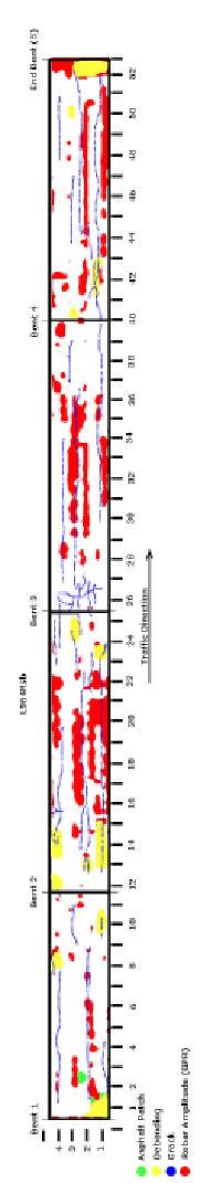
4 Figure 2. Example bridge L964R North, Kingdom City, MO. Lateral amplitude and phase variations, perhaps due to design and construction, make interpretation more challenging in terms of possible deteriorated sections. The degradation of the radar signal shows up as a loss in amplitude of the rebar reflection and an increase in travel time to the rebar layer. Both of these changes in signature are indications that the rebar is deteriorated and the region above the rebar is compromised in some fashion. Although we do not image or measure debonding or delamination directly, the radar reflection character may be related directly to the amount of debonding/delamination which allows (chloride-bearing) fluids to reach the rebar mat. After detailed visual assessment and/or amplitude mapping, we produce a contour plot of each bridge deck showing good and bad areas. Where visual assessment was not possible (Figure 2), we used only variation in the radar reflection amplitude from the top rebar mat as indicative of possible deterioration. Using strictly a visual assessment, we automatically come up with a black and white result (i.e., it is either bad or good). Using the character of the top rebar mat, our result is a contour plot of amplitude or two-way travel time (indicative of velocity variation) that is more of a continuum. We must calibrate these plots in order to determine what the cut-off values must be for determining good versus bad. Figure 3 displays interpretation results for bridge #A9012 (St. Charles) where we used rebar amplitude mapping. Figures 4-13 show the results of our analyses as well as ground truth for each of the other bridges. Figure 3a. Map-view of rebar reflection amplitude contoured after data analysis of bridge #A9012 (St. Charles). Dark spots are hot, associated with loss of radar amplitude indicating that bridge integrity in those areas may be compromised. 4
5 Figure 3b. Map-view of interpreted condition assessment after rebar reflection amplitude analysis of bridge #A9012 (St. Charles). Colored spots highlight surface patches as well as debonding determined by chain drag testing. Figure 4. Map-view of interpreted condition assessment after visual analysis of radar data for bridge #A2682 southbound (Arnold). Colored spots highlight surface patches as well as debonding determined by chain drag testing. Also plotted are half-cell potential results and chloride sample locations. Figure 5. Map-view of interpreted condition assessment after visual analysis of radar data for bridge #A2682 northbound (Arnold). Colored areas highlight surface cracking as well as core and chloride sample locations. Also plotted are half-cell potential results. 5
6 Figure 6. Map-view of interpreted condition assessment after visual analysis of radar data for #A2683 southbound (Arnold). Colored areas highlight debonding (determined by chain drag testing), half-cell potential results, and locations of chloride sampling. Figure 7. Map-view of interpreted condition assessment after visual analysis of radar data for #A2683 northbound (Arnold). Colored areas highlight debonding (from chain drag testing) and half-cell potential results. Also noted are core and chloride sample locations. Figure 8. Map-view of interpreted condition assessment after visual analysis of radar data for #A2684 southbound (Arnold). Colored spots highlight debonding (determined by chain drag testing) and half-cell potential results. Also noted are chloride sample locations. 6
7 Figure 9. Map-view of interpreted condition assessment after visual analysis of radar data for #A2684 northbound (Arnold). Colored spots highlight debonding (determined by chain drag testing) and half-cell potential results. Also noted are chloride sample locations. 7
8 8
9 Figure 12. Map-view of interpreted condition assessment after visual analysis of radar data for bridge #H284N (Kingdom City). Colored spots highlight surface patches as well as debonding determined by chain drag testing. Figure 13a. Map-view of interpreted condition assessment after visual analysis of radar data for bridge #A2109 (Kingdom City). Colored areas highlight surface patches as well as debonding determined by chain drag testing. Chloride sample locations are noted. Figure 13b. Map-view of interpreted condition assessment of bridge #A2109 (Kingdom City). Colored areas highlight same features as in Figure 13a with results from rebar amplitude analysis shown as well. 9
10 CONCLUSIONS In this paper we have demonstrated the utility of ground penetrating radar to image subsurface structure within rebar-reinforced concrete bridge decks. Mapping the degradation of the radar signal (i.e., the loss in amplitude and/or an increase in travel time for returns from internal layering) gives an indication whether or not the rebar is deteriorated and the region above the rebar is compromised in some fashion. The radar reflection character may be related directly to the amount of debonding/delamination which allows (chloride-bearing) fluids to reach the rebar. Using strictly a visual assessment, we automatically come up with a result showing good and bad areas of the bridge that is in good agreement with ground truth. Using the radar reflection character of the top rebar mat, we produce a contour plot of amplitude or two-way travel time (indicative of velocity variation) that is a continuum across the bridge deck. We must calibrate these contour plots in order to determine what the cut-off values must be for determining good versus bad. We might guess that each bridge has a condition that is a continuum, from very good areas to very bad areas, and thus the black and white delineation is not as accurate. However, when trying to determine percent deterioration of a bridge, the black and white descriptor is required. The good correlation with ground truth shows that GPR can give percent deterioration estimates that are accurate. The determination of the type of deterioration (delamination, debonding) using GPR alone is much more difficult. Results of this work suggest that GPR may yield good estimates of chain drag hollow areas related to debonding, as well as possibly the areas showing up in half-cell potential data related to rebar corrosion. REFERENCES ASTM Designation D , Standard Practice for Measuring Delaminations in Concrete Bridge Decks by Sounding. AASHTO Designation TP36-93, Standard Test Method for Evaluating Asphalt-Covered Concrete Bridge Decks Using Pulsed Radar. Cardimona, S., M. Roark, D. J. Webb and T. Lippincott, Ground penetrating radar, Highway Applications of Engineering Geophysics with an Emphasis on Previously Mined Ground, pp Daniels, D., Surface-penetrating radar, Inst. Electr. Eng. 10
Ground Penetrating Radar Survey of. Interstate 70 Across Missouri
 Ground Penetrating Radar Survey of Interstate 70 Across Missouri Steve Cardimona *, Brent Willeford *, Doyle Webb *, John Wenzlick +, Neil Anderson * * The University of Missouri-Rolla, Department of Geology
Chapter 4 Results. 4.1 Pattern recognition algorithm performance
 94 Chapter 4 Results 4.1 Pattern recognition algorithm performance The results of analyzing PERES data using the pattern recognition algorithm described in Chapter 3 are presented here in Chapter 4 to
Ground Penetrating Radar (GPR) By Dr. Eng. Zubair Ahmed
 By Dr. Eng. Zubair Ahmed") Ground Penetrating Radar (GPR) By Dr. Eng. Zubair Ahmed Acknowledgement Golder Associates, Whitby, Ontario Stantec Consulting, Kitchener, Ontario Infrasense Inc. USA Geophysical Survey Systems Inc. (GSSI),
Ground Penetrating Radar (GPR) By Dr. Eng. Zubair Ahmed Acknowledgement Golder Associates, Whitby, Ontario Stantec Consulting, Kitchener, Ontario Infrasense Inc. USA Geophysical Survey Systems Inc. (GSSI),
Standard Test Method for Evaluating Asphalt-Covered Concrete Bridge Decks Using Ground Penetrating Radar 1
 Designation: D 6087 08 Standard Test Method for Evaluating Asphalt-Covered Concrete Bridge Decks Using Ground Penetrating Radar 1 This standard is issued under the fixed designation D 6087; the number
Diagnostics of Bridge Pavements by Ground Penetrating Radar
 11th European Conference on Non-Destructive Testing (ECNDT 2014), October 6-10, 2014, Prague, Czech Republic Diagnostics of Bridge Pavements by Ground Penetrating Radar Radek MATULA 1, Josef STRYK 1, Karel
Advances in NDE Technology WHATS NEW?
 Advances in NDE Technology WHATS NEW? Glen Simula, Owner GS Infrastructure, Inc. The state of America s deteriorating infrastructure presses us to find solutions to assess, with limited funds and resources.
The use of high frequency transducers, MHz, allowing the resolution to target a few cm thick in the first half meter suspect.
 METHODOLOGY GPR (GROUND PROBING RADAR). In recent years the methodology GPR (Ground Probing Radar) has been applied with increasing success under the NDT thanks to the high speed and resolving power. As
Adapting a Ground Coupled GPR Threshold Model for Use with Air Coupled GPR Systems
 International Symposium Non-Destructive Testing in Civil Engineering (NDT-CE) More Info at Open Access Database www.ndt.net/?id=18339 September 15-17, 2015, Berlin, Germany Adapting a Ground Coupled GPR
GPR SURVEY METHOD. Ground probing radar
 The ground penetrating radar (GPR - Ground Probing Radar) is a geophysical method used to investigate the near surface underground. Thanks to its high degree of resolution, the GPR is the most effective
Tri-band ground penetrating radar for subsurface structural condition assessments and utility mapping
 Tri-band ground penetrating radar for subsurface structural condition assessments and utility mapping D. Huston *1, T. Xia 1, Y. Zhang 1, T. Fan 1, J. Razinger 1, D. Burns 1 1 University of Vermont, Burlington,
ESTIMATION OF REBAR DIAMETER IN CONCRETE STRUCTURAL ELEMENTS USING GROUND PENETRATING RADAR
 More info about this article: http://www.ndt.net/?id=21143 ESTIMATION OF REBAR DIAMETER IN CONCRETE STRUCTURAL ELEMENTS USING GROUND PENETRATING RADAR Bhaskar Sangoju and Ramanjaneyulu, K. Scientists,
Attenuation-based Methodology for Condition Assessment of Concrete Bridge Decks using GPR
 The 32st International Symposium on Automation and Robotics in Construction and Mining (ISARC), June 15-18, 2015, Oulu, Finland. Attenuation-based Methodology for Condition Assessment of Concrete Bridge
GPR SYSTEM USER GUIDE AND TROUBLESHOOTING GUIDE
 GPR SYSTEM USER GUIDE AND TROUBLESHOOTING GUIDE Implementation Report 5-4414-01-1 Project Number 5-4414-01 Subsurface Sensing Lab Electrical and Computer Engineering University of Houston 4800 Calhoun
GPR Investigation: Post Tension Cable Mapping
 CMD Civil Pty Ltd PO Box 1119 Huntingdale VIC 3166 +61 3 9544 8833 info@cmdcivil.com www.cmdcivil.com Case Study: GPR Investigation: Post Tension Cable Mapping This application note demonstrates an example
Advanced Methods to Identify Asphalt Pavement Delamination (R06D) Ground Penetrating Radar (GPR) Caltrans
 Ground Penetrating Radar (GPR) Caltrans") Advanced Methods to Identify Asphalt Pavement Delamination (R06D) Ground Penetrating Radar (GPR) Caltrans William Owen Peer Exchange August 1-3, 2018 Introduction How We Got Here Strategic Highway Research
Advanced Methods to Identify Asphalt Pavement Delamination (R06D) Ground Penetrating Radar (GPR) Caltrans William Owen Peer Exchange August 1-3, 2018 Introduction How We Got Here Strategic Highway Research
Advanced Methods to Identify Asphalt Pavement Delamination (R06D) Minnesota DOT Evaluation: Calibration and Signal Analysis
 Minnesota DOT Evaluation: Calibration and Signal Analysis") Advanced Methods to Identify Asphalt Pavement Delamination (R06D) Minnesota DOT Evaluation: Calibration and Signal Analysis Ken Maser, Infrasense Shongtao Dai, Research Operations Engineer Kyle Hoegh,
Advanced Methods to Identify Asphalt Pavement Delamination (R06D) Minnesota DOT Evaluation: Calibration and Signal Analysis Ken Maser, Infrasense Shongtao Dai, Research Operations Engineer Kyle Hoegh,
Report. Mearns Consulting LLC. Former Gas Station 237 E. Las Tunas Drive San Gabriel, California Project # E
 Mearns Consulting LLC Report Former Gas Station 237 E. Las Tunas Drive San Gabriel, California Project #1705261E Charles Carter California Professional Geophysicist 20434 Corisco Street Chatsworth, CA
Non-Destructive Bridge Deck Assessment using Image Processing and Infrared Thermography. Masato Matsumoto 1
 Non-Destructive Bridge Deck Assessment using Image Processing and Infrared Thermography Abstract Masato Matsumoto 1 Traditionally, highway bridge conditions have been monitored by visual inspection with
Amplitudes Variation of GPR Rebar Reflection Due to the Influence of Concrete Aggregate Scattering
 More Info at Open Access Database www.ndt.net/?id=18402 Amplitudes Variation of GPR Rebar Reflection Due to the Influence of Concrete Aggregate Scattering Thomas KIND Federal Institute for Materials Research
On the Use of Ground Penetrating Radar to Detect Rebar Corrosion in Concrete Structures
 On the Use of Ground Penetrating Radar to Detect Rebar Corrosion in Concrete Structures David Eisenmann, CNDE, ISU Frank J. Margetan, CNDE, ISU Shelby Ellis, ISU This work is supported by the Iowa DOT
Advanced Ground Investigation Techniques to Help Limit Risk or Examine Failure. Advanced Subsurface Investigations
 Advanced Ground Investigation Techniques to Help Limit Risk or Examine Failure Overview Introduction What is geophysics? Why use it? Common Methods Seismic Ground Radar Electrical Case Studies Conclusion
Non-destructive Evaluation of Bituminous Compaction Uniformity Using Rolling Density
 Non-destructive Evaluation of Bituminous Compaction Uniformity Using Rolling Density October 2017 Lev Khazanovich, PhD Kyle Hoegh, PhD Ryan Conway Shongtao Dai, PhD, PE University of Pittsburgh University
State-of-the-Art Bridge Deck Condition Evaluation and Management Using Ground Penetrating Radar
 State-of-the-Art Bridge Deck Condition Evaluation and Management Using Ground Penetrating Radar Christopher L. Barnes a, Ph.D., P.Eng., Senior Materials Engineer, AMEC Environment and Infrastructure Paper
GPR Data Acquisition and Interpretation
 1 GPR Data Acquisition and Interpretation Mezgeen Rasol PhD Candidate Geophysics and Seismic Engineering Polytechnic University of Catalonia mezgeen.rasol@upc.edu BIG-SKY-EARTH Cost Action TD143 Workshop
1. Report No. FHWA/TX-05/ Title and Subtitle PILOT IMPLEMENTATION OF CONCRETE PAVEMENT THICKNESS GPR
 1. Report No. FHWA/TX-05/5-4414-01-3 4. Title and Subtitle PILOT IMPLEMENTATION OF CONCRETE PAVEMENT THICKNESS GPR Technical Report Documentation Page 2. Government Accession No. 3. Recipient s Catalog
Archaeo-Geophysical Associates, LLC
 Geophysical Survey at the Parker Cemetery Rockwall, Texas. AGA Report 2010-6 Report Submitted To: Texas Cemetery Restoration 10122 Cherry Tree Dr. Dallas, Texas 75243 May 14, 2010 Chester P. Walker, Ph.D.
Radar Methods General Overview
 Environmental and Exploration Geophysics II Radar Methods General Overview tom.h.wilson tom.wilson@mail.wvu.edu Department of Geology and Geography West Virginia University Morgantown, WV Brown (2004)
Ground Penetrating Radar (day 1) EOSC Slide 1
 EOSC Slide 1") Ground Penetrating Radar (day 1) Slide 1 Introduction to GPR Today s Topics Setup: Motivational Problems Physical Properties - Dielectric Permittivity and Radiowaves - Microwave Example Basic Principles:
Ground Penetrating Radar (day 1) Slide 1 Introduction to GPR Today s Topics Setup: Motivational Problems Physical Properties - Dielectric Permittivity and Radiowaves - Microwave Example Basic Principles:
SCANNING METHOD. Olson Instruments Impact Echo Scanner. incorporating source and receiver. Overlay. Sound joint between. overlay and bridge deck
 IE Method N D E I M P A C T E C H O S C A N N I N G A PPLICATION Impact Echo (IE) investigations are performed to assess the condition of slabs, beams, columns, walls, pavements, runways, tunnels, and
Estimaton of Rebar Diameter Using Ground Penetrating Radar
 International Journal of Advances in Scientific Research and Engineering (ijasre) E-ISSN : 2454-8006 Vol.3, Special Issue 1 Aug - 2017 Estimaton of Rebar Diameter Using Ground Penetrating Radar K Ambika
Pave-IR Scan TM Primer
 SHRP2 Solution: Technologies to Enhance Quality Control on Asphalt Pavements Introduction Pave-IR Scan TM Primer In-place density is a critical factor in determining pavement durability in hot mix asphalt
Automated Pavement Subsurface Profiling Using Radar: Case Studies of Four Experimental Field Sites
 148 TRANSPORTATION RESEARCH RECORD 1344 Automated Pavement Subsurface Profiling Using Radar: Case Studies of Four Experimental Field Sites KENNETH R. MASER AND TOM SCULLION Accurate knowledge of pavement
Ground Penetrating Radar
 REPORT 4A Ground Penetrating Radar Introduction to GPR, and positioning of GPR data Part of R&D project Infrastructure in 3D in cooperation between Innovation Norway, Trafikverket and TerraTec Yta för
GPR Part II: Effects of conductivity. Surveying geometries. Noise in GPR data. Summary notes with essential equations. Some Case histories
 GPR Part II: Effects of conductivity Surveying geometries Noise in GPR data Summary notes with essential equations Some Case histories EOSC 350 06 Slide 1 GPR Ground Penetrating Radar R = ε ε 2 2 + ε ε
SIMULATION OF GPR SCENARIOS USING FDTD
 SIMULATION OF GPR SCENARIOS USING FDTD 1 GAMIL ALSHARAHI, 2 ABDELLAH DRIOUACH, 3 AHMED FAIZE 1,2 Department of physic, Abdelmalek Essaâdi University, Faculty of sciences, Morocco 3 Department of physic,
REBAR DETECTION USING GPR: AN EMERGING NON DESTRUCTIVE QC APPROACH
 REBAR DETECTION USING GPR: AN EMERGING NON DESTRUCTIVE QC APPROACH D.C.Bala*, R.D.Garg** and S.S. Jain*** *(Research scholar, Centre for Transportation Systems (CTRANS), IIT Roorkee, Roorkee-247667, India
7. Consider the following common offset gather collected with GPR.
 Questions: GPR 1. Which of the following statements is incorrect when considering skin depth in GPR a. Skin depth is the distance at which the signal amplitude has decreased by a factor of 1/e b. Skin
Applied Geophysics Nov 2 and 4
 Applied Geophysics Nov 2 and 4 Effects of conductivity Surveying geometries Noise in GPR data Summary notes with essential equations Some Case histories EOSC 350 06 Slide 1 GPR Ground Penetrating Radar
LAB 9: GROUND-PENETRATING RADAR
 NAME: LAB TIME: LAB 9: GROUND-PENETRATING RADAR The following lab will introduce you to the basic concepts of Ground-Penetrating Radar (GPR) in part I. In part II, we will conduct a field geophysical survey
THE BEST GPR DATA QUALITY AT THE BEST PRICE! GROUND PENETRATING RADAR ZOND-12e G R O U N D P E N E T R A T I N G R A D A R S
 GROUND PENETRATING RADAR ZOND-12e General Purpose Pulse GPR ZOND-12e SINGLE CHANNEL OR ADVANCED CONTROL UNITS ZOND 12e GPR is a portable digital Ground Penetrating Radar carried by a single operator. The
Resolution in evaluation of structural elements by using ground-penetrating radar.
 Resolution in evaluation of structural elements by using ground-penetrating radar. V. Perez-Gracia Departamento de Resistencia de Materiales y Estructuras en la Ingeniería. EUETIB/CEIB. Universidad Politécnica
TxDOT Project : Evaluation of Pavement Rutting and Distress Measurements
 0-6663-P2 RECOMMENDATIONS FOR SELECTION OF AUTOMATED DISTRESS MEASURING EQUIPMENT Pedro Serigos Maria Burton Andre Smit Jorge Prozzi MooYeon Kim Mike Murphy TxDOT Project 0-6663: Evaluation of Pavement
GPR Inspection of Bridge Decks
 All rights reserved including the right of reproduction in whole or in part in any form Published by Geophysical Survey Systems, Inc. 40 Simon St. Nashua, New Hampshire 03060 USA Printed in the United
FHWA/TX F EVALUATION OF STRESS-WAVE METHODS FOR IMPLEMENTATION INTO A ROLLING SYSTEM TO DETECT PAVEMENT IRREGULARITIES
 1. Report No. 2. Government Accession No. FHWA/TX-95-1243-5F 4. Tide and Subtitle EVALUATION OF STRESS-WAVE METHODS FOR IMPLEMENTATION INTO A ROLLING SYSTEM TO DETECT PAVEMENT IRREGULARITIES 7. Author(s)
HEALTH MONITORING OF ROCK BOLTS USING ULTRASONIC GUIDED WAVES
 HEALTH MONITORING OF ROCK BOLTS USING ULTRASONIC GUIDED WAVES C. He 1, J. K. Van Velsor 2, C. M. Lee 2, and J. L. Rose 2 1 Beijing University of Technology, Beijing, 100022 2 The Pennsylvania State University,
Modeling of Ground-Penetrating Radar Wave Propagation in Pavement Systems
 TRANSPORTATION RESEARCH RECORD 1355 99 Modeling of Ground-Penetrating Radar Wave Propagation in Pavement Systems CHUN LOK LAU, TOM SCULLION, AND PAUL CHAN In recent years considerable attention has been
GROUND PENETRATING RADAR (GEORADAR) INSPECTION
 INSPECTION") - CIVIL ENGENEERING - GEOLOGY AND ENVIRONMENT - GROUND PENETRATING RADAR - LOSSES DETECTING RADAR SYSTEM - ARCHEOLOGY & CULTURAL HERITAGE - CARGO INSPECTION - LOSS CONTROL - CHEMICAL ANALYSIS - INDUSTRIAL
- CIVIL ENGENEERING - GEOLOGY AND ENVIRONMENT - GROUND PENETRATING RADAR - LOSSES DETECTING RADAR SYSTEM - ARCHEOLOGY & CULTURAL HERITAGE - CARGO INSPECTION - LOSS CONTROL - CHEMICAL ANALYSIS - INDUSTRIAL
Case Studies and Innovative Uses of GPR for Pavement Engineering Applications
 Case Studies and Innovative Uses of GPR for Pavement Engineering Applications Richard Korczak, MASc., P.Eng., Stantec Consulting Ltd. Amir Abd El Halim, PhD., P.Eng., Stantec Consulting Ltd. Paper prepared
Ground Penetrating Radar
 Ground Penetrating Radar Begin a new section: Electromagnetics First EM survey: GPR (Ground Penetrating Radar) Physical Property: Dielectric constant Electrical Permittivity EOSC 350 06 Slide Di-electric
Using GPR Technique Assessment for Study the Sub-Grade of Asphalt and Concrete Conditions
 Using GPR Technique Assessment for Study the Sub-Grade of Asphalt and Concrete Conditions Alaa S. Mahdi Remote Sensing Unit, College of Science, University of Baghdad, Baghdad, Iraq Abstract The Ground
Geophysical Survey Rock Hill Bleachery TBA Site Rock Hill, South Carolina EP-W EPA, START 3, Region 4 TABLE OF CONTENTS Section Page Signature
 Geophysical Survey Rock Hill Bleachery TBA Site Rock Hill, South Carolina EP-W-05-054 EPA, START 3, Region 4 Prepared for: Tetra Tech EM, Inc. October 12, 2012 Geophysical Survey Rock Hill Bleachery TBA
ωκε ωκε 5.11 Ground Penetrating Radar (GPR)
") 5. Ground Penetrating Radar (GPR) The plane wave solutions we have studied so far have been valid for frequencies and conductivities such that the conduction currents dominate the displacement currents
5. Ground Penetrating Radar (GPR) The plane wave solutions we have studied so far have been valid for frequencies and conductivities such that the conduction currents dominate the displacement currents
Recommendations for guidelines for the use of GPR in bridge deck surveys
 Recommendations for guidelines for the use of GPR in bridge deck surveys Mara Nord Project in cooperation with: European Commission, Finnish Transport Agency, Swedish Transport Administration, Norwegian
RADAR INSPECTION OF CONCRETE, BRICK AND MASONRY STRUCTURES
 RADAR INSPECTION OF CONCRETE, BRICK AND MASONRY STRUCTURES C.P.Hobbs AEA Industrial Technology Materials and Manufacturing Division Nondestructive Testing Department Building 447 Harwell Laboratory Oxon
TPF-5(188), Evaluation of Fiber Reinforced Composite Dowel Bars and Stainless Steel Dowel Bars
, Evaluation of Fiber Reinforced Composite Dowel Bars and Stainless Steel Dowel Bars") TPF-5(188), Evaluation of Fiber Reinforced Composite Dowel Bars and Stainless Steel Dowel Bars Research Review Session October 13, 2011 TPF-5(188) Project Team Technical Panel Roger Green, Ohio DOT (Chairman)
TPF-5(188), Evaluation of Fiber Reinforced Composite Dowel Bars and Stainless Steel Dowel Bars Research Review Session October 13, 2011 TPF-5(188) Project Team Technical Panel Roger Green, Ohio DOT (Chairman)
Dowel Alignment: Measurement and Impacts on Pavement Performance
 Dowel Alignment: Measurement and Impacts on Pavement Performance prepared by: Mark B. Snyder, Ph.D., P.E. Vice-President, ACPA-PA Chapter for: ACPA s 2012 Annual Meeting Concrete Pavement University November
Exploration Beyond Expectation. Geo-Carte Radar Technology Pvt. Ltd.
 Exploration Beyond Expectation Geo-Carte Radar Technology Pvt. Ltd. Problem Unknown distribution network of underground pipeline in India 32% Damage of pre-existing underground utilities during laying
ScienceDirect. A comparison of dielectric constants of various asphalts calculated from time intervals and amplitudes
 Available online at www.sciencedirect.com ScienceDirect Procedia Engineering 111 (2015 ) 660 665 XXIV R-S-P seminar, Theoretical Foundation of Civil Engineering (24RSP) (TFoCE 2015) A comparison of dielectric
MEASURING ELECTROMAGNETIC PROPERTIES OF ASPHALT FOR PAVEMENT QUALITY CONTROL AND DEFECT MAPPING
 MEASURING ELECTROMAGNETIC PROPERTIES OF ASPHALT FOR PAVEMENT QUALITY CONTROL AND DEFECT MAPPING Timo Saarenketo Roadscanners Rovaniemi, FINLAND timo.saarenketo@roadscanners.com 1. INTRODUCTION This paper
EVALUATING STEEL-REINFORCED CONCRETE BRIDGE DECKS USING GROUND-PENETRATING RADAR: MODELS FOR DETERIORATION. A Thesis Presented
 EVALUATING STEEL-REINFORCED CONCRETE BRIDGE DECKS USING GROUND-PENETRATING RADAR: MODELS FOR DETERIORATION A Thesis Presented by Christopher Franklin Wright to The Department of Civil and Environmental
Using ground penetrating radar to quantify changes in the fracture pattern associated with a simulated rockburst experiment
 Using ground penetrating radar to quantify changes in the fracture pattern associated with a simulated rockburst experiment by M. Grodner* Synopsis Ground Penetrating Radar (GPR) is an electromagnetic
Experiment on Artificial Frozen Soil Boundary GPR Detection During Cross-passage Construction in Tunnels
 354 Progress In Electromagnetics Research Symposium 2005, Hangzhou, China, August 22-26 Experiment on Artificial Frozen Soil Boundary GPR Detection During Cross-passage Construction in Tunnels Yong-Hui
Form DOT F (8-72) 'This fonn was electrically by Elite Federal Fonns Inc. Reproduction of completed page authorized
 'This fonn was electrically by Elite Federal Fonns Inc. Reproduction of completed page authorized") l.report No. / 12. Government Accession No. 3. Recipient's Catalog No. TxDOT4172-4. Title and Subtitle 5. Report Date Development of a Radar System for the Non-Destructive Measurement of Feb.2001 Concrete
l.report No. / 12. Government Accession No. 3. Recipient's Catalog No. TxDOT4172-4. Title and Subtitle 5. Report Date Development of a Radar System for the Non-Destructive Measurement of Feb.2001 Concrete
Fundamental Study on NDT of Building Wall Structure by Radar
 7th European Workshop on Structural Health Monitoring July 8-11, 2014. La Cité, Nantes, France More Info at Open Access Database www.ndt.net/?id=17135 Fundamental Study on NDT of Building Wall Structure
In search of a Historic Grave: GPR Investigation near the Yellowstone Lake Store: 7/15/2010
 In search of a Historic Grave: GPR Investigation near the Yellowstone Lake Store: 7/15/2010 Steven Sheriff Professor of Geophysics Department of Geosciences University of Montana Missoula, Montana Introduction
GPR MEASUREMENTS OF WATER LEVEL IN SILTY SOILS. Sandeep Pyakurel
 GPR MEASUREMENTS OF WATER LEVEL IN SILTY SOILS Sandeep Pyakurel Problem report submitted to the College of Engineering and Mineral Resources at West Virginia University in partial fulfillment of the requirements
A Report on the Ground Penetrating Radar Survey 205 Little Plains Road Southampton, NY
 A Report on the Ground Penetrating Radar Survey 205 Little Plains Road Southampton, NY November 18, 2016 Conducted by Robert W. Perry TOPOGRAPHIX, LLC Hudson, NH Requested by Southampton Town Historical
Hiding In Plain Sight. How Ultrasonics Can Help You Find the Smallest Bonded Wafer and Device Defects. A Sonix White Paper
 Hiding In Plain Sight How Ultrasonics Can Help You Find the Smallest Bonded Wafer and Device Defects A Sonix White Paper If You Can See It, You Can Solve It: Understanding Ultrasonic Inspection of Bonded
CENTER FOR INFRASTRUCTURE ENGINEERING STUDIES
 1 CENTER FOR INFRASTRUCTURE ENGINEERING STUDIES Nondestructive Ultrasonic Detection of FRP Delamination By Dr. Norbert Maerz University Transportation Center Program at UTC R81 The University of Missouri-Rolla
MICROWAVE SUB-SURFACE IMAGING TECHNOLOGY FOR DAMAGE DETECTION
 MICROWAVE SUB-SURFACE IMAGING TECHNOLOGY FOR DAMAGE DETECTION By Yoo Jin Kim 1, Associate Member, ASCE, Luis Jofre 2, Franco De Flaviis 3, and Maria Q. Feng 4, Associate Member, ASCE Abstract: This paper
Multipath and Diversity
 Multipath and Diversity Document ID: 27147 Contents Introduction Prerequisites Requirements Components Used Conventions Multipath Diversity Case Study Summary Related Information Introduction This document
Quick Assessment of the Anomalies in Concrete Structure Using Dispersive Characteristic of Surface wave
 Quick Assessment of the Anomalies in Concrete Structure Using Dispersive Characteristic of Surface wave Chia-Chi Cheng 1 *, Keng-Tsang Hsu 1, Chih-Hung Chiang 1, Fong-Jhang Ke 1, and Hong- Hua Wang 1 1
Surface Deployed / Ground Sensors
 Surface Deployed / Ground Sensors WS2 Vibro-acoustics WS3 - Non-Contact Electrical Resistivity techniques WS3 Electromagnetic methods WS4 Detecting changes in the ground Key Achievements and Findings Surface
3D UTILITY MAPPING USING ELECTRONICALLY SCANNED ANTENNA ARRAY. Egil S. Eide and Jens F. Hjelmstad
 D UTILITY MAPPING USING ELECTRONICALLY SCANNED ANTENNA ARRAY Egil S. Eide and Jens F. Hjelmstad Department of Telecommunications Norwegian University of Science and Technology, N-79 Trondheim, Norway eide@tele.ntnu.no
Visual inspection and ground penetrating radar investigation of the historical Pulaski County Poor Farm Cemetery
 Scholars' Mine Masters Theses Student Theses and Dissertations Fall 2011 Visual inspection and ground penetrating radar investigation of the historical Pulaski County Poor Farm Cemetery Ibrahim Elshiekh
European Scientific Journal February 2014 /SPECIAL/ edition vol.3 ISSN: (Print) e - ISSN
 e - ISSN") HIGH PRECISION CALCULATION OF MOVE OUT CORRECTION IN GPR MEASUREMENTS Janis Karuss, M.Sc. University of Latvia, Latvia Abstract Ground penetrating radar (GPR) is a non-invasive geophysical method that
HIGH PRECISION CALCULATION OF MOVE OUT CORRECTION IN GPR MEASUREMENTS Janis Karuss, M.Sc. University of Latvia, Latvia Abstract Ground penetrating radar (GPR) is a non-invasive geophysical method that
Integration of Traditional and Non- Traditional Remote Sensing for Bridge Condition Assessment
 Integration of Traditional and Non- Traditional Remote Sensing for Bridge Condition Assessment Tess Ahlborn, Ph.D., P.E., FPCI Devin Harris, Ph.D., Colin Brooks and Larry Sutter, Ph.D. Michigan Technological
Dragging Exploration into the Quantum Age: using Atomic Dielectric Resonance technology to classify sites in the North Atlantic Craton
 Dragging Exploration into the Quantum Age: using Atomic Dielectric Resonance technology to classify sites in the North Atlantic Craton Gordon D.C. Stove CEO & Co-founder Agenda What is Atomic Dielectric
Ultrasonic Guided Wave Applications
 Ultrasonic Guided Wave Applications Joseph L. Rose Penn State University April 29-30, 2013 2013 Center for Acoustics and Vibrations meeting What is a Guided Wave? (Guided wave requires boundary for propagation
PCCP Preservation Steps to Take to Extend Pavement Life and Performance of Your Concrete Pavements
 PCCP Preservation Steps to Take to Extend Pavement Life and Performance of Your Concrete Pavements Larry Scofield, P.E. International Grooving and Grinding Association 1 Big Preservation Everybody Wins
MICROWAVE FIELD MEASUREMENT OF DELAMINATIONS IN CFRP CONCRETE MEMBERS IN A BRIDGE
 MICROWAVE FIELD MEASUREMENT OF DELAMINATIONS IN CFRP CONCRETE MEMBERS IN A BRIDGE V. Stephen, S. Kharkovsky, J. Nadakuduti, R. Zoughi; Applied Microwave Nondestructive Testing Laboratory (amntl), Department
Form DOT F (8-72) This form was electrically by Elite Federal Forms Inc. 16. Abstract:
 This form was electrically by Elite Federal Forms Inc. 16. Abstract:") 1. Report No. FHWA/TX-06/0-4820-3 4. Title and Subtitle Investigation of a New Generation of FCC Compliant NDT Devices for Pavement Layer Information Collection: Technical Report 2. Government Accession
1. Report No. FHWA/TX-06/0-4820-3 4. Title and Subtitle Investigation of a New Generation of FCC Compliant NDT Devices for Pavement Layer Information Collection: Technical Report 2. Government Accession
Use of Vitreous-Ceramic Coatings on Reinforcing Steel for Pavements
 Use of Vitreous-Ceramic Coatings on Reinforcing Steel for Pavements Charles A. Weiss, Jr. 1 Sean W. Morefield 2, Philip G. Malone 1, Michael L. Koenigstein 3 1 Geotechnical and Structures Laboratory 2
Results of GPR survey of AGH University of Science and Technology test site (Cracow neighborhood).
.") Results of GPR survey of AGH University of Science and Technology test site (Cracow neighborhood). October 02, 2017 Two GPR sets were used for the survey. First GPR set: low-frequency GPR Loza-N [1]. Technical
Results of GPR survey of AGH University of Science and Technology test site (Cracow neighborhood). October 02, 2017 Two GPR sets were used for the survey. First GPR set: low-frequency GPR Loza-N [1]. Technical
Advanced Utility Locating Technologies (R01B)
") Advanced Utility Locating Technologies (R01B) Jacob Sheehan Senior Geophysicist Olson Engineering Phil Sirles Principal Geophysicist Olson Engineering Introduction: Utility Bundle Overview SHRP2 Strategic
Advanced Utility Locating Technologies (R01B) Jacob Sheehan Senior Geophysicist Olson Engineering Phil Sirles Principal Geophysicist Olson Engineering Introduction: Utility Bundle Overview SHRP2 Strategic
COBRA CBD UNPARALLELED QUALITY GPR DATA WITHOUT BLIND SPOTS
 COBRA CBD WIRELESS GPR Introducing the smart CBD ANTENNA Triple frequency 200/400/800 MHz Outstanding 50-1400 MHz bandwidth Replaces several conventional antennas UNPARALLELED QUALITY GPR DATA WITHOUT
Assessment of layer thickness and uniformity in railway embankments with Ground Penetrating Radar
 Assessment of layer thickness and uniformity in railway embankments with Ground Penetrating Radar F.M. Fernandes Department of Civil Engineering, University of Minho, Guimarães, Portugal M. Pereira Geotechnique
Analysis of Crack Detection in Metallic and Non-metallic Surfaces Using FDTD Method
 ECNDT 26 - We.4.3.2 Analysis of Crack Detection in Metallic and Non-metallic Surfaces Using FDTD Method Faezeh Sh.A.GHASEMI 1,2, M. S. ABRISHAMIAN 1, A. MOVAFEGHI 2 1 K. N. Toosi University of Technology,
P Forsmark site investigation. RAMAC and BIPS logging in borehole HFM11 and HFM12
 P-04-39 Forsmark site investigation RAMAC and BIPS logging in borehole HFM11 and HFM12 Jaana Gustafsson, Christer Gustafsson Malå Geoscience AB/RAYCON March 2004 Svensk Kärnbränslehantering AB Swedish
INTERNAL CONCRETE INSPECTION AND EVALUATION METHODS FOR STEEL PLATE-BONDED SLABS BY USING ELASTIC WAVES VIA ANCHOR BOLTS
 More info about this article: h Czech Society for Nondestructive Testing 32 nd European Conference on Acoustic Emission Testing Prague, Czech Republic, September 7-9, 216 INTERNAL CONCRETE INSPECTION AND
Pitfalls in GPR Data Interpretation: Differentiating Stratigraphy and Buried Objects from Periodic Antenna and Target Effects
 GEOPHYSICAL RESEARCH LETTERS, VOL. 27, NO. 20, PAGES 3393-3396, OCTOBER 15, 2000 Pitfalls in GPR Data Interpretation: Differentiating Stratigraphy and Buried Objects from Periodic Antenna and Target Effects
I 2. Government Accession No.
 I. ReportNo. I 2. Government Accession No. TX98/2964S 4. Title and Subtitle DETECTING STRIPPING IN ASPHALT CONCRETE LAYERS USING GROUNDPENETRATING RADAR 7. Author(s) Tom Scullion and Elias Rmeili 9. Performing
SIR, UtilityScan and RADAN are registered trademarks of Geophysical Survey Systems, Inc.
 Copyright 2016-2017 Geophysical Survey Systems, Inc. All rights reserved including the right of reproduction in whole or in part in any form Published by Geophysical Survey Systems, Inc. 40 Simon Street
VALIDATION OF GROUND PENETRATING RADAR DATA INTERPRETATION USING AN ELECTROMAGNETIC WAVE PROPAGATION SIMULATOR
 Romanian Reports in Physics, Vol. 68, No. 4, P. 1584 1588, 2016 VALIDATION OF GROUND PENETRATING RADAR DATA INTERPRETATION USING AN ELECTROMAGNETIC WAVE PROPAGATION SIMULATOR A. CHELMUS National Institute
Magnetic Eddy Current (MEC) Inspection Technique
 Inspection Technique") Introduction Eddy Current Testing (ECT) is a well established technology for the inspection of metallic components for surface breaking flaws. It is used for component testing in the aviation and automotive
Introduction Eddy Current Testing (ECT) is a well established technology for the inspection of metallic components for surface breaking flaws. It is used for component testing in the aviation and automotive
Determine the Thickness of Pavement Layers Variety Using GPR Technique in Some Sites at University of Kufa, Najaf, Iraq
 International Journal of ChemTech Research CODEN (USA): IJCRGG, ISSN: 0974-4290, ISSN(Online):2455-9555 Vol.10 No.2, pp 837-843, 2017 Determine the Thickness of Pavement Layers Variety Using GPR Technique
Downloaded from library.seg.org by on 10/26/14. For personal use only. SEG Technical Program Expanded Abstracts 2014
 Ground penetrating abilities of broadband pulsed radar in the 1 70MHz range K. van den Doel, Univ. of British Columbia, J. Jansen, Teck Resources Limited, M. Robinson, G. C, Stove, G. D. C. Stove, Adrok
PRACTICAL ASPECTS OF ACOUSTIC EMISSION SOURCE LOCATION BY A WAVELET TRANSFORM
 PRACTICAL ASPECTS OF ACOUSTIC EMISSION SOURCE LOCATION BY A WAVELET TRANSFORM Abstract M. A. HAMSTAD 1,2, K. S. DOWNS 3 and A. O GALLAGHER 1 1 National Institute of Standards and Technology, Materials
CHAPTER 10 MICHIGAN DESIGN MANUAL BRIDGE DESIGN (SI) SHOP DRAWING REVIEW TYPES OF SHOP DRAWINGS Structural Steel
 SHOP DRAWING REVIEW TYPES OF SHOP DRAWINGS Structural Steel") CHAPTER 10 SHOP DRAWING REVIEW 10.01 TYPES OF SHOP DRAWINGS 10.01.01 Structural Steel 10.01.02 Prestressed Concrete 10.01.03 Bearings 10.01.04 Metal Stay - In - Place Forms () 10.01.05 Expansion Joints
CHAPTER 10 SHOP DRAWING REVIEW 10.01 TYPES OF SHOP DRAWINGS 10.01.01 Structural Steel 10.01.02 Prestressed Concrete 10.01.03 Bearings 10.01.04 Metal Stay - In - Place Forms () 10.01.05 Expansion Joints
In-Situ Damage Detection of Composites Structures using Lamb Wave Methods
 In-Situ Damage Detection of Composites Structures using Lamb Wave Methods Seth S. Kessler S. Mark Spearing Mauro J. Atalla Technology Laboratory for Advanced Composites Department of Aeronautics and Astronautics