Dr. Ali Muqaibel. Associate Professor. Electrical Engineering Department King Fahd University of Petroleum & Minerals Dhahran, Saudi Arabia
|
|
|
- Brett Sims
- 5 years ago
- Views:
Transcription

1 By Associate Professor Electrical Engineering Department King Fahd University of Petroleum & Minerals Dhahran, Saudi Arabia Wednesday, December 1, 14 1 st Saudi Symposium for RADAR Technology 9 1 December 14 Riyadh, Saudi Arabia 1
2 Outline Introduction to TWRI Applications High Resolution(UWB, SAR) Image Formation Challenges Multipath propagation and ghosts Front wall effects Antenna directivity Image formation Wall characterization and compensation Measurement Results Compensation Results Conclusion Recommendations
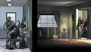
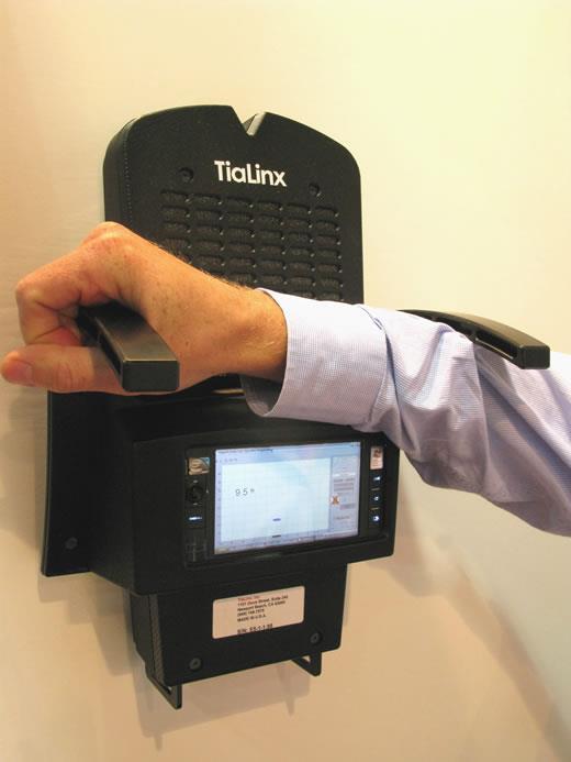
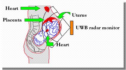
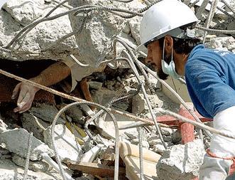
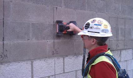
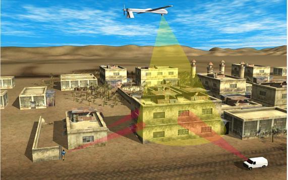
3 Applications & Prototypes
 Use of Wide")

4 High Resolution Imaging To get higher resolution Image: 1) Use of Wide bandwidth (UWB) ) Use Wide Aperture, Antenna Array or Synthetic Aperture (SAR) 4
/ Advantages Trade bandwidth for a reduced transmission power Immunity to multipath Low cost and low complexity (promissed) Disadvantages Coexistence with")
5 What is UWB? UWB signals have BW > 5 MHz or B f. = BW f c = f H f L (f H +f L )/ Advantages Trade bandwidth for a reduced transmission power Immunity to multipath Low cost and low complexity (promissed) Disadvantages Coexistence with other systems Fast ADC requirement Application High data rate/ High positioning resolution Short distance Low power Though-wall imaging 5
6 Synthetic Aperture Radar 6

7 Beamforming & Image Formation Target τ mp τ mq M M II I xx q q = w w m m s t τ mp + ττ mq m=1 m=1 7 h tt t=

8 Image Formation (SAR) 8
9 Challenges in TWRI 1. Multipath Propagation & Ghosts. Front Wall: 1. Attenuation. Reflection 3. Reverberation (ringing) 3. Thermal noise & Interference 4. Limited Measurement Capability 9
10 Multipath 1

11 Ghost Formation Number of Targets= z-axis "pixel" Ghosts Target x-axis "pixel" 11
12 Front Wall 1
13 Front Wall Compensation Objective: Compensate for the UWB through-wall propagation Why? How? EM waves through a wall gets attenuated slows down gets dispersed Attributed to dispersive and attenuative properties of the wall In localization and Imaging: Defocuses target image Displaces the target from its true position. Investigating the interaction of the electromagnetic wave incident on the wall Characterizing the wall in terms of electrical properties (insertion transfer function, delay, dielectric constant, insertion loss etc) Using the wall model to compensate for the wall effect 13


14 Literature in Wall Characterization Literature Building Material Methodology Frequency Reported Parameters Application Type Condition Structure Simulation Theoretical Experimental Oblique incidence Direct incidence UWB X Band S Band 16 GHz 1 1 GHz Dielectric constant Insertion loss Return loss Transmission coefficient Reflection coefficient Communication Imaging Detection & Localization RF/Shielding Delay Loss tangent 14
15 Short Background on Dielectric Properties of Walls Every material has a unique set of electrical characteristics dependent on its dielectric properties Dielectric stores energy when an external electric field is applied Electric flux density D is: r = absolute permittivity, ε r = relative permittivity, ε = permittivity of free space E = the electric field. Permittivity complex quantity. Dielectric constant = relative permittivity (ε r ) (ε r ) energy storage (ε r ) - loss factor 15 r D E ' r j '' r Parameter r tan d Τ loss tangent = energy lost energy stored '' r = tan ' r Meaning dielectric Constant conductivity delay loss tangent slab thickness propagation constant Attenuation coefficient Phase coefficient Reflection coefficient Transmission coefficient
16 Measurement Setup Measuring magnitude and phase components are important in that They are needed to fully characterize the obstruction IFFT - impulse response characterization Calibration Measurements can be performed in both time domain and frequency domain techniques using coaxial or transmission line methods, or free-space radiated methods Frequency domain Higher dynamic range No synchronization Noise reduction techniques Free-space radiated setup Contactless, non-destructive Proper machining with cavity/waveguide Matches the final application (radar, communication) 16


17 Frequency Domain Setup Amplifier Network Analyzer Antenna Antenna air air 1.5 m cable Wall N-type to SMA connector Low noise amplifier Port 1 Vector Network Analyzer Port 4.5 m cable 1.5 m cable S Parameter Test Set Data Processing Wideband cables 17
 Et ( j) Ei ( j) fs Et ( j) E ( j) i E E t fs t ( j) ( j) X X t fs t ( j) ( j) 18 z S 1 ( j) H( j) e j d")
18 Transmission Measurement Free Space E i E t fs Region II (Material) Region I (Air) Region III (Air) E i E r d E t H ( j) Et ( j) Ei ( j) fs Et ( j) E ( j) i E E t fs t ( j) ( j) X X t fs t ( j) ( j) 18 z S 1 ( j) H( j) e j d c


19 Reflection Measurements Wall Material Metallic Reflector 19
20 Analysis Method Dielectric constant is related to insertion transfer function through a complex equation Free Space Incident wave establishes E i E t fs Reflected wave in region I (air) Forward-backward traveling waves in region II(wall) Transmitted wave in region III(air) Region II (Material) Imposing boundary conditions for E and H fields, Region I (Air) Region III (Air) E i E t E r d z
21 Wall Parameter Calculation Summary S 1 frequency Domain Transmission & Reflection measurements -1 - Freespace Through Wall S1( free space) H( j) S ( through wall ) 1 Filter IFFT on S 1 data, with zero padding to obtain impulse response Peak-to-peak time domain differential delay using a sliding correlator. First estimate of delay and loss Time gating to remove unwanted reflections FFT H( j) (gated) Use low loss equations r ' '', r H ( j) e ' Magnitude, Magnitude, db Amplitude in (V) x Insertion Transfer Function Filter Filtered Insertion transfer function Frequency, GHz Amplitude in (V) x 1-4 Freespace Impulse Response Through 8 wall Impulse 1 Response 1 14 time, ns 6 1 x ' ' ( j ) d 6 r 1 ( j ) d r 1 e ' ' 4 r r - c Amplitude (V) ' ' r r e jd Freespace Impulse Response Through wall Impulse Response.4*Window(Free space).4*window(through wall) Free-Space Impulse Resopnse Through Impulse Response time in secs x Dielectric constant, Loss tangent, Attenuation constant time, ns
22 Measurement Results Transmission and Reflection results Comparing Transmission & Reflection Repeatability & Variability Compare with Literature Multiple Walls Accuracy Related Issues
23 Insertion Transfer Function (Magnitude), db db Insertion Transfer Function (Magnitude), db db Transmission Transmission Wood Wood -8 Gypsum -8 Glass Gypsum Glass Frequency, 8 GHz Frequency, GHz Transmission Transmission Wood - fit Wood fit -8 Gypsum - fit -8 Gypsum fit Glass - fit Glass fit Frequency, GHz Frequency, GHz 3 Insertion transfer function Coefficients of linear or quadratic fits to extracted the parameters af + b or af + bf + c, f(ghz) Wood Glass Gypsum a b c a b c a b c
24 Diecletric Constant Diecletric Constant Reflection Reflection Reflection false solutions Wood Wood Gypsum Gypsum Glass Glass Frequency, GHz Frequency, GHz Diecletric Constant Diecletric Constant Reflection Reflection Wood - fit Wood - fit Gypsum - fit Gypsum - fit Glass - fit Glass - fit Frequency, 8 1 GHz Frequency, GHz Coefficients of linear or quadratic fits to extracted the parameters af + b or af + bf + c, f(ghz) 4 Wood Glass Gypsum a b c a b c a b c Dielectric constant


25 Multiple walls Single wood wall Double glass wall air gap 5 Spaced wall: wood and gypsum Three layer: glass-woodglass
26 Double layer walls -1 x Free-space single wood double wood 8 6 Free-space single wood double wood -3 4 Magnitude, db -4-5 Amplitude (V) Frequency, GHz time, secs x 1-9 single wood double wood Insertion Transfer Function, db Frequency, GHz
27 Spaced double walls (Air gap) Free-space free space with cm with 5cm with 1cm Magnitude, db various air gap sizes Frequency, GHz 1 x free space various air gap sizes Free-space cm 5cm 1cm.4 Amplitude (V) time, secs x 1-9

28 Sources of Error Antenna Antenna Characteristics Alignment Antenna-Wall separation Cables & Connectors Cable length Connector mismatch Accuracy Related Issues Measurement setup & Lab environment Air-gaps, edge effects Scatterers Repeatability and Variability Magnitude, db GHz Cable A Cable B Cable C Cable ABC Frequency, GHz 8
29 Insertion Transfer Function, db Insertion Transfer Function, db Repeatability and Variability Wood, Meas 1 Wood, Meas Wood Frequency, GHz Repeatability of measurements allows us obtain the same results for measurements taken at different instances of time for the same wall sample Measurements are said to have low variability if they yield approximately the same results for different samples of the same material Dielectric constant Dielectric constant Wood,, Meas 1 Wood Wood,, Meas Meas Wood Wood Frequency, 8 GHz Frequency, GHz
30 5 x 1-4 Wood Wall Compensation Amplitude, V -5 Target Only (Everything except wall) Target + Wall (Everything + Wall) Compensated Time, sec x 1-9 x 1-4 Glass Amplitude, V 4 - Target Only (Everything except wall) Target + Wall (Everything + Wall) Compensated -4 Amplitude, V x Gypsum Target Only (Everything except wall) Target + Wall (Everything + Wall) Compensated Time, sec x Time, sec x 1-9
31 Wall Compensation Correct the adverse effect of the wall On the outcome of the detection process so that the true target position can be obtained On the pulse shape for imaging communication & receiver design purposes Using 3 methods Constant Amplitude and Delay (CAD) Frequency Dependent Data (FDD) Data Fitting (FIT) 31


32 Target Measurement Target Only Target + Wall d1 x 1-4 Target Object range Tx Rx Measurement System Amplitude, V - Target Only Target + Wall d antenna -4 3 Wall Material Time, sec x 1-9
33 Constant Amplitude & Delay Method (CAD) S 1 frequency Domain Transmission & Reflection measurements S1( free space) H( j) S ( through wall ) 1 Filter Assumption of Constant amplitude attenuation Constant delay due to wall S 1 frequency Domain Target measurements Target + Wall IFFT Target Only IFFT IFFT on S 1 data, with zero padding to obtain impulse response Target + Wall Target Only Peak-to-peak time domain differential delay using a sliding correlator. First estimate of delay and loss CAD a Target +Wall t_shift Compensated version of Target Only Time gating to remove unwanted reflections FFT H( j) (gated) 1 x Freespace Impulse Response Through wall Impulse Response a thruwall ( t) freespace ( t) Use low loss equations Amplitude in (V) - t _ shift ( transmissi on) r ' '', r Dielectric constant, Loss tangent, Attenuation constant time in secs x 1-9
34 Comparing the three Methods x 1-4 Wood Target Only Target + Wall CAD-Compensated FDD-Compensated FIT-Compensated Amplitude, V Time, sec x
35 Summary Conclusion Wideband EM characterization of walls (unique band) Wood, glass, gypsum Transmission and Reflection Insertion loss, dielectric constant 1-18 GHz Results compare good with literature Multiple walls Double layer Three layer Wall compensation Constant Amplitude & Delay (CAD) Frequency Dependent Data (FDD) Data Fitting (FIT) 35
36 Current Research: Direction with Single Antenna 36


37 THANK YOU Book Chapter A. H. Muqaibel, M. Al-Sunaidi, N. M. Iya and A. Safaai-Jazi, Chapter 1: Wall Attenuation and Dispersion, Book title: "Through Wall Radar Imaging". Publisher: CRC Press. Publication Date: Dec 13 1 Acknowledgment Mr. Mohammad Tamim Al-Khdary for Helping in preparing this presentation
Experimental Evaluation Scheme of UWB Antenna Performance
 Tokyo Tech. Experimental Evaluation Scheme of UWB Antenna Performance Sathaporn PROMWONG Wataru HACHITANI Jun-ichi TAKADA TAKADA-Laboratory Mobile Communication Research Group Graduate School of Science
Ground Penetrating Radar
 Ground Penetrating Radar Begin a new section: Electromagnetics First EM survey: GPR (Ground Penetrating Radar) Physical Property: Dielectric constant Electrical Permittivity EOSC 350 06 Slide Di-electric
Project: IEEE P Working Group for Wireless Personal Area Networks N
 Project: IEEE P82.15 Working Group for Wireless Personal Area Networks N (WPANs( WPANs) Title: [UWB Channel Measurement Results in Indoor Residential Environment High-Rise Apartments] Date Submitted: [19
Ultra Wideband Indoor Radio Channel Measurements
 Ultra Wideband Indoor Radio Channel Measurements Matti Hämäläinen, Timo Pätsi, Veikko Hovinen Centre for Wireless Communications P.O.Box 4500 FIN-90014 University of Oulu, FINLAND email: matti.hamalainen@ee.oulu.fi
Channel Modeling ETI 085
 Channel Modeling ETI 085 Overview Lecture no: 9 What is Ultra-Wideband (UWB)? Why do we need UWB channel models? UWB Channel Modeling UWB channel modeling Standardized UWB channel models Fredrik Tufvesson
MICROWAVE SCATTERING FOR THE CHARACTERIZATION OF A DISC-SHAPE VOID IN DIELECTRIC MATERIALS AND COMPOSITES
 MICROWAVE SCATTERING FOR THE CHARACTERIZATION OF A DISC-SHAPE VOID IN DIELECTRIC MATERIALS AND COMPOSITES John M. Liu Code 684 Naval Surface Warfare Center Carderock Div. West Bethesda, Md. 20817-5700
7. Experiment K: Wave Propagation
 7. Experiment K: Wave Propagation This laboratory will be based upon observing standing waves in three different ways, through coaxial cables, in free space and in a waveguide. You will also observe some
Index Terms - Attenuation Constant(α), MB-OFDM Signal, Propagation Constant( β), TWI.
, MB-OFDM Signal, Propagation Constant( β), TWI.") Through-The-Wall Propagation and Channel Modeling G. Nagaraja 1,G.Balaji 2 1 Research Scholar in Department of Electronics and Communications Engineering, Shri Venkateshwara University, Gajraula, Amorha,
Through-The-Wall Propagation and Channel Modeling G. Nagaraja 1,G.Balaji 2 1 Research Scholar in Department of Electronics and Communications Engineering, Shri Venkateshwara University, Gajraula, Amorha,
Project: IEEE P Working Group for Wireless Personal Area Networks N
 Project: IEEE P82.15 Working Group for Wireless Personal Area Networks N (WPANs( WPANs) Title: [UWB Channel Model for Indoor Residential Environment] Date Submitted: [2 September, 24] Source: [Chia-Chin
UWB Channel Modeling
 Channel Modeling ETIN10 Lecture no: 9 UWB Channel Modeling Fredrik Tufvesson & Johan Kåredal, Department of Electrical and Information Technology fredrik.tufvesson@eit.lth.se 2011-02-21 Fredrik Tufvesson
Radar Imaging of Concealed Targets
 Radar Imaging of Concealed Targets Vidya H A Department of Computer Science and Engineering, Visveswaraiah Technological University Assistant Professor, Channabasaveshwara Institute of Technology, Gubbi,
Coupled Sectorial Loop Antenna (CSLA) for Ultra Wideband Applications
 for Ultra Wideband Applications") Coupled Sectorial Loop Antenna (CSLA) for Ultra Wideband Applications N. Behdad and K. Sarabandi Presented by Nader Behdad at Antenna Application Symposium, Monticello, IL, Sep 2004 Email: behdad@ieee.org
Coupled Sectorial Loop Antenna (CSLA) for Ultra Wideband Applications N. Behdad and K. Sarabandi Presented by Nader Behdad at Antenna Application Symposium, Monticello, IL, Sep 2004 Email: behdad@ieee.org
EITN85, FREDRIK TUFVESSON, JOHAN KÅREDAL ELECTRICAL AND INFORMATION TECHNOLOGY. Why do we need UWB channel models?
 Wireless Communication Channels Lecture 9:UWB Channel Modeling EITN85, FREDRIK TUFVESSON, JOHAN KÅREDAL ELECTRICAL AND INFORMATION TECHNOLOGY Overview What is Ultra-Wideband (UWB)? Why do we need UWB channel
Signal Integrity Testing with a Vector Network Analyzer. Neil Jarvis Applications Engineer
 Signal Integrity Testing with a Vector Network Analyzer Neil Jarvis Applications Engineer 1 Agenda RF Connectors A significant factor in repeatability and accuracy Selecting the best of several types for
Validation & Analysis of Complex Serial Bus Link Models
 Validation & Analysis of Complex Serial Bus Link Models Version 1.0 John Pickerd, Tektronix, Inc John.J.Pickerd@Tek.com 503-627-5122 Kan Tan, Tektronix, Inc Kan.Tan@Tektronix.com 503-627-2049 Abstract
EXPERIMENT EM3 INTRODUCTION TO THE NETWORK ANALYZER
 ECE 351 ELECTROMAGNETICS EXPERIMENT EM3 INTRODUCTION TO THE NETWORK ANALYZER OBJECTIVE: The objective to this experiment is to introduce the student to some of the capabilities of a vector network analyzer.
Physical Test Setup for Impulse Noise Testing
 Physical Test Setup for Impulse Noise Testing Larry Cohen Overview Purpose: Use measurement results for the EM coupling (Campbell) clamp to determine a stable physical test setup for impulse noise testing.
CHAPTER 2 MICROSTRIP REFLECTARRAY ANTENNA AND PERFORMANCE EVALUATION
 43 CHAPTER 2 MICROSTRIP REFLECTARRAY ANTENNA AND PERFORMANCE EVALUATION 2.1 INTRODUCTION This work begins with design of reflectarrays with conventional patches as unit cells for operation at Ku Band in
Detection of Multipath Propagation Effects in SAR-Tomography with MIMO Modes
 Detection of Multipath Propagation Effects in SAR-Tomography with MIMO Modes Tobias Rommel, German Aerospace Centre (DLR), tobias.rommel@dlr.de, Germany Gerhard Krieger, German Aerospace Centre (DLR),
Design and experimental realization of the chirped microstrip line
 Chapter 4 Design and experimental realization of the chirped microstrip line 4.1. Introduction In chapter 2 it has been shown that by using a microstrip line, uniform insertion losses A 0 (ω) and linear
(i) Determine the admittance parameters of the network of Fig 1 (f) and draw its - equivalent circuit.
 Determine the admittance parameters of the network of Fig 1 (f) and draw its - equivalent circuit.") I.E.S-(Conv.)-1995 ELECTRONICS AND TELECOMMUNICATION ENGINEERING PAPER - I Some useful data: Electron charge: 1.6 10 19 Coulomb Free space permeability: 4 10 7 H/m Free space permittivity: 8.85 pf/m Velocity
I.E.S-(Conv.)-1995 ELECTRONICS AND TELECOMMUNICATION ENGINEERING PAPER - I Some useful data: Electron charge: 1.6 10 19 Coulomb Free space permeability: 4 10 7 H/m Free space permittivity: 8.85 pf/m Velocity
Thu Truong, Michael Jones, George Bekken EE494: Senior Design Projects Dr. Corsetti. SAR Senior Project 1
 Thu Truong, Michael Jones, George Bekken EE494: Senior Design Projects Dr. Corsetti SAR Senior Project 1 Outline Team Senior Design Goal UWB and SAR Design Specifications Design Constraints Technical Approach
APPLIED ELECTROMAGNETICS: EARLY TRANSMISSION LINES APPROACH
 APPLIED ELECTROMAGNETICS: EARLY TRANSMISSION LINES APPROACH STUART M. WENTWORTH Auburn University IICENTBN Nlfll 1807; WILEY 2 OO 7 ; Ttt^TlLtftiTTu CONTENTS CHAPTER1 Introduction 1 1.1 1.2 1.3 1.4 1.5
3D Directional Coupler for Impulse UWB
 3D Directional Coupler for Impulse UWB 3D Electromagnetic Simulation and Prototyping Julien Le Kernec* Martin Klepal** Vratislave Sokol*** * ONERA, the French Aerospace Lab, Electromagnetic and Radar Department,
ECE 476/ECE 501C/CS Wireless Communication Systems Winter Lecture 6: Fading
 ECE 476/ECE 501C/CS 513 - Wireless Communication Systems Winter 2005 Lecture 6: Fading Last lecture: Large scale propagation properties of wireless systems - slowly varying properties that depend primarily
ECE 476/ECE 501C/CS Wireless Communication Systems Winter Lecture 6: Fading
 ECE 476/ECE 501C/CS 513 - Wireless Communication Systems Winter 2004 Lecture 6: Fading Last lecture: Large scale propagation properties of wireless systems - slowly varying properties that depend primarily
Chapter 4 Radio Communication Basics
 Chapter 4 Radio Communication Basics Chapter 4 Radio Communication Basics RF Signal Propagation and Reception Basics and Keywords Transmitter Power and Receiver Sensitivity Power - antenna gain: G TX,
MAKING TRANSIENT ANTENNA MEASUREMENTS
 MAKING TRANSIENT ANTENNA MEASUREMENTS Roger Dygert, Steven R. Nichols MI Technologies, 1125 Satellite Boulevard, Suite 100 Suwanee, GA 30024-4629 ABSTRACT In addition to steady state performance, antennas
DEVELOPMENT AND TESTING OF THE TIME-DOMAIN MICROWAVE NON. Fu-Chiarng Chen and Weng Cho Chew
 DEVELOPMENT AND TESTING OF THE TIME-DOMAIN MICROWAVE NON DESTRUCTIVE EVALUATION SYSTEM Fu-Chiarng Chen and Weng Cho Chew Electromagnetics Laboratory Center for Computational Electromagnetics Department
Telecommunication Systems February 14 th, 2019
 Telecommunication Systems February 14 th, 019 1 3 4 5 do not write above SURNAME AND NAME ID NUMBER SIGNATURE Problem 1 A radar with zenithal pointing, working at f = 5 GHz, illuminates an aircraft with
Overview. Measurement of Ultra-Wideband Wireless Channels
 Measurement of Ultra-Wideband Wireless Channels Wasim Malik, Ben Allen, David Edwards, UK Introduction History of UWB Modern UWB Antenna Measurements Candidate UWB elements Radiation patterns Propagation
ANTENNA INTRODUCTION / BASICS
 ANTENNA INTRODUCTION / BASICS RULES OF THUMB: 1. The Gain of an antenna with losses is given by: 2. Gain of rectangular X-Band Aperture G = 1.4 LW L = length of aperture in cm Where: W = width of aperture
Γ L = Γ S =
 TOPIC: Microwave Circuits Q.1 Determine the S parameters of two port network consisting of a series resistance R terminated at its input and output ports by the characteristic impedance Zo. Q.2 Input matching
AIR-GAP DETECTION IN DIELECTRIC MATERIALS BY A STEP-FREQUENCY MICROWAVE TECHNIQUE
 AR-GAP DETECTON N DELECTRC MATERALS BY A STEP-FREQUENCY MCROWAVE TECHNQUE John M. Liu Code 684 Carderock Division, White Oak Det. Naval Surface Warfare Center Silver Spring, Md. 20903-5640 NTRODUCTON Most
Time Domain Characteristics of Multiple UWB 2D Communication Tiles
 Proceedings of the 2015 IEEE/SICE International Symposium on System Integration, pp.817-822, December 11-13, 2015 Time Domain Characteristics of Multiple UWB 2D Communication Tiles Akimasa Okada, Akihito
Multiple Phase Screen Calculation of Wide Bandwidth Prop Pro a p gation Dennis L. Knepp L J Nickisch
 Multiple Phase Screen Calculation of Wide Bandwidth Propagation Dennis L. Knepp L. J. Nickisch NorthWest Research Associates 28 URSI General Assembly Chicago, August 28 Outline Summary of MPS technique
Ultra Wideband Transceiver Design
 Ultra Wideband Transceiver Design By: Wafula Wanjala George For: Bachelor Of Science In Electrical & Electronic Engineering University Of Nairobi SUPERVISOR: Dr. Vitalice Oduol EXAMINER: Dr. M.K. Gakuru
General MIMO Framework for Multipath Exploitation in Through-the-Wall Radar Imaging
 General MIMO Framework for Multipath Exploitation in Through-the-Wall Radar Imaging Michael Leigsnering, Technische Universität Darmstadt Fauzia Ahmad, Villanova University Moeness G. Amin, Villanova University
USE OF MICROWAVES FOR THE DETECTION OF CORROSION UNDER INSULATION
 USE OF MICROWAVES FOR THE DETECTION OF CORROSION UNDER INSULATION R. E. JONES, F. SIMONETTI, M. J. S. LOWE, IMPERIAL COLLEGE, London, UK I. P. BRADLEY, BP Exploration and Production Company, Sunbury on
Ultra Wideband Radio Propagation Measurement, Characterization and Modeling
 Ultra Wideband Radio Propagation Measurement, Characterization and Modeling Rachid Saadane rachid.saadane@gmail.com GSCM LRIT April 14, 2007 achid Saadane rachid.saadane@gmail.com ( GSCM Ultra Wideband
Aries Kapton CSP socket
 Aries Kapton CSP socket Measurement and Model Results prepared by Gert Hohenwarter 5/19/04 1 Table of Contents Table of Contents... 2 OBJECTIVE... 3 METHODOLOGY... 3 Test procedures... 4 Setup... 4 MEASUREMENTS...
Measurement Notes. Note 53. Design and Fabrication of an Ultra-Wideband High-Power Zipper Balun and Antenna. Everett G. Farr Farr Research, Inc.
 Measurement Notes Note 53 Design and Fabrication of an Ultra-Wideband High-Power Zipper Balun and Antenna Everett G. Farr Farr Research, Inc. Gary D. Sower, Lanney M. Atchley, and Donald E. Ellibee EG&G
Calibration Concepts of Multi-Channel Spaceborne SAR
 DLR.de Chart 1 > CEOS Workshop 2016 > Tobias Rommel > September 7 th, 2016 Calibration Concepts of Multi-Channel Spaceborne SAR T. Rommel, F. Queiroz de Almeida, S. Huber, M. Jäger, G. Krieger, C. Laux,
Department of Electrical and Computer Engineering ECE332. Lab 3: High Frequency Measurements
 Department of Electrical and Computer Engineering ECE332 Version: 1.3.1 Revised: April 30, 2011 Contents 1 Pre-Lab Assignment 2 2 Introduction 2 2.1 Vector Network Analyzer.............................
Chapter 7 Design of the UWB Fractal Antenna
 Chapter 7 Design of the UWB Fractal Antenna 7.1 Introduction F ractal antennas are recognized as a good option to obtain miniaturization and multiband characteristics. These characteristics are achieved
UWB Multipath Simulator based on TEM Horn Antenna
 UWB Multipath Simulator based on TEM Horn Antenna A. H. Muqaibel Electrical Engineering Department, King Fahd University of Petroleum & Minerals, P.O. Box 1734, Dhahran 31261, KSA muqaibel@kfupm.edu.sa
Antenna Measurements using Modulated Signals
 Antenna Measurements using Modulated Signals Roger Dygert MI Technologies, 1125 Satellite Boulevard, Suite 100 Suwanee, GA 30024-4629 Abstract Antenna test engineers are faced with testing increasingly
RANGE resolution and dynamic range are the most important
 INTL JOURNAL OF ELECTRONICS AND TELECOMMUNICATIONS, 2012, VOL. 58, NO. 2, PP. 135 140 Manuscript received August 17, 2011; revised May, 2012. DOI: 10.2478/v10177-012-0019-1 High Resolution Noise Radar
The Radio Channel. COS 463: Wireless Networks Lecture 14 Kyle Jamieson. [Parts adapted from I. Darwazeh, A. Goldsmith, T. Rappaport, P.
 The Radio Channel COS 463: Wireless Networks Lecture 14 Kyle Jamieson [Parts adapted from I. Darwazeh, A. Goldsmith, T. Rappaport, P. Steenkiste] Motivation The radio channel is what limits most radio
ECE 4265/6265 Laboratory Project 7 Network Analyzer Calibration
 ECE 4265/6265 Laboratory Project 7 Network Analyzer Calibration Objectives The purpose of this lab is to introduce the concepts of calibration and error correction for microwave s-parameter measurements.
Time Domain Reflectometry (TDR) and Time Domain Transmission (TDT) Measurement Fundamentals
 and Time Domain Transmission (TDT) Measurement Fundamentals") Time Domain Reflectometry (TDR) and Time Domain Transmission (TDT) Measurement Fundamentals James R. Andrews, Ph.D., IEEE Fellow PSPL Founder & former President (retired) INTRODUCTION Many different kinds
Time Domain Reflectometry (TDR) and Time Domain Transmission (TDT) Measurement Fundamentals James R. Andrews, Ph.D., IEEE Fellow PSPL Founder & former President (retired) INTRODUCTION Many different kinds
CHAPTER 3 METHODOLOGY AND SOFTWARE TOOLS
 CHAPTER 3 METHODOLOGY AND SOFTWARE TOOLS Microstrip Patch Antenna Design In this chapter, the procedure for designing of a rectangular microstrip patch antenna is described. The proposed broadband rectangular
UWB Double-Directional Channel Sounding
 2004/01/30 Oulu, Finland UWB Double-Directional Channel Sounding - Why and how? - Jun-ichi Takada Tokyo Institute of Technology, Japan takada@ide.titech.ac.jp Table of Contents Background Antennas and
Final Report for AOARD Grant FA Indoor Localization and Positioning through Signal of Opportunities. Date: 14 th June 2013
 Final Report for AOARD Grant FA2386-11-1-4117 Indoor Localization and Positioning through Signal of Opportunities Date: 14 th June 2013 Name of Principal Investigators (PI and Co-PIs): Dr Law Choi Look
Antenna Measurement Uncertainty Method for Measurements in Compact Antenna Test Ranges
 Antenna Measurement Uncertainty Method for Measurements in Compact Antenna Test Ranges Stephen Blalock & Jeffrey A. Fordham MI Technologies Suwanee, Georgia, USA Abstract Methods for determining the uncertainty
A Printed Wideband MIMO Antenna System for GSM1800/1900, UMTS, WLAN2450, LTE2300/2500, and GPS Applications
 Progress In Electromagnetics Research C, Vol. 70, 33 41, 2016 A Printed Wideband MIMO Antenna System for GSM1800/1900, UMTS, WLAN2450, LTE2300/2500, and GPS Applications Mohamed M. Morsy* Abstract A low-profile
ECE 476/ECE 501C/CS Wireless Communication Systems Winter Lecture 6: Fading
 ECE 476/ECE 501C/CS 513 - Wireless Communication Systems Winter 2003 Lecture 6: Fading Last lecture: Large scale propagation properties of wireless systems - slowly varying properties that depend primarily
Amplifier Characterization in the millimeter wave range. Tera Hertz : New opportunities for industry 3-5 February 2015
 Amplifier Characterization in the millimeter wave range Tera Hertz : New opportunities for industry 3-5 February 2015 Millimeter Wave Converter Family ZVA-Z500 ZVA-Z325 Y Band (WR02) ZVA-Z220 J Band (WR03)
Microwave and optical systems Introduction p. 1 Characteristics of waves p. 1 The electromagnetic spectrum p. 3 History and uses of microwaves and
 Microwave and optical systems Introduction p. 1 Characteristics of waves p. 1 The electromagnetic spectrum p. 3 History and uses of microwaves and optics p. 4 Communication systems p. 6 Radar systems p.
IMAGE FORMATION THROUGH WALLS USING A DISTRIBUTED RADAR SENSOR NETWORK. CIS Industrial Associates Meeting 12 May, 2004 AKELA
 IMAGE FORMATION THROUGH WALLS USING A DISTRIBUTED RADAR SENSOR NETWORK CIS Industrial Associates Meeting 12 May, 2004 THROUGH THE WALL SURVEILLANCE IS AN IMPORTANT PROBLEM Domestic law enforcement and
EM Noise Mitigation in Electronic Circuit Boards and Enclosures
 EM Noise Mitigation in Electronic Circuit Boards and Enclosures Omar M. Ramahi, Lin Li, Xin Wu, Vijaya Chebolu, Vinay Subramanian, Telesphor Kamgaing, Tom Antonsen, Ed Ott, and Steve Anlage A. James Clark
SHF Communication Technologies AG. Wilhelm-von-Siemens-Str. 23D Berlin Germany. Phone Fax
 SHF Communication Technologies AG Wilhelm-von-Siemens-Str. 23D 12277 Berlin Germany Phone +49 30 772051-0 Fax ++49 30 7531078 E-Mail: sales@shf.de Web: http://www.shf.de Datasheet SHF 100 BPP Broadband
Practical Measurements of Dielectric Constant and Loss for PCB Materials at High Frequency
 8 th Annual Symposium on Signal Integrity PENN STATE, Harrisburg Center for Signal Integrity Practical Measurements of Dielectric Constant and Loss for PCB Materials at High Frequency Practical Measurements
Comparison of IC Conducted Emission Measurement Methods
 IEEE TRANSACTIONS ON INSTRUMENTATION AND MEASUREMENT, VOL. 52, NO. 3, JUNE 2003 839 Comparison of IC Conducted Emission Measurement Methods Franco Fiori, Member, IEEE, and Francesco Musolino, Member, IEEE
A Hybrid Indoor Tracking System for First Responders
 A Hybrid Indoor Tracking System for First Responders Precision Indoor Personnel Location and Tracking for Emergency Responders Technology Workshop August 4, 2009 Marc Harlacher Director, Location Solutions
Politecnico di Torino. Porto Institutional Repository
 Politecnico di Torino Porto Institutional Repository [Proceeding] Integrated miniaturized antennas for automotive applications Original Citation: Vietti G., Dassano G., Orefice M. (2010). Integrated miniaturized
Application Note 5525
 Using the Wafer Scale Packaged Detector in 2 to 6 GHz Applications Application Note 5525 Introduction The is a broadband directional coupler with integrated temperature compensated detector designed for
Measuring PCB, Cable and Interconnect Impedance, Dielectric Constants, Velocity Factor, and Lengths
 Measuring PCB, Cable and Interconnect Impedance, Dielectric Constants, Velocity Factor, and Lengths Controlled impedance printed circuit boards (PCBs) often include a measurement coupon, which typically
A New TEM Horn Antenna Designing Based on Plexiglass Antenna Cap
 Journal of Applied Science and Engineering, Vol. 21, No. 3, pp. 413 418 (2018) DOI: 10.6180/jase.201809_21(3).0012 A New TEM Horn Antenna Designing Based on Plexiglass Antenna Cap Lin Teng and Jie Liu*
Lecture 19 Optical Characterization 1
 Lecture 19 Optical Characterization 1 1/60 Announcements Homework 5/6: Is online now. Due Wednesday May 30th at 10:00am. I will return it the following Wednesday (6 th June). Homework 6/6: Will be online
UWB 2D Communication Tiles
 2014 IEEE International Conference on Ultra-Wideband (ICUWB), pp.1-5, September 1-3, 2014. UWB 2D Communication Tiles Hiroyuki Shinoda, Akimasa Okada, and Akihito Noda Graduate School of Frontier Sciences
Antennas Studies for UWB Radio
 Antennas Studies for UWB Radio Program Review May 22 Professor Daniel H. Schaubert Electrical and Computer Engineering University of Massachusetts at Amherst Amherst, MA 3 schaubert@ecs.umass.edu UWB Radio
Active Ultra-Wideband Tag Design for Concrete Debris Tracking Systems
 Active Ultra-Wideband Tag Design for Concrete Debris Tracking Systems Y. Z. Shen± C. L. Law* K. S. Koh S. M. Hu School of Electrical and Electronic Engineering, Nanyang Technological University, Singapore
UWB SHORT RANGE IMAGING
 ICONIC 2007 St. Louis, MO, USA June 27-29, 2007 UWB SHORT RANGE IMAGING A. Papió, J.M. Jornet, P. Ceballos, J. Romeu, S. Blanch, A. Cardama, L. Jofre Department of Signal Theory and Communications (TSC)
Aries QFP microstrip socket
 Aries QFP microstrip socket Measurement and Model Results prepared by Gert Hohenwarter 2/18/05 1 Table of Contents Table of Contents... 2 OBJECTIVE... 3 METHODOLOGY... 3 Test procedures... 4 Setup... 4
Design and Development of Rectangular Microstrip Array Antennas for X and Ku Band Operation
 International Journal of Electronics Engineering, 2 (2), 2010, pp. 265 270 Design and Development of Rectangular Microstrip Array Antennas for X and Ku Band Operation B. Suryakanth, NM Sameena, and SN
SIZE REDUCTION AND BANDWIDTH ENHANCEMENT OF A UWB HYBRID DIELECTRIC RESONATOR AN- TENNA FOR SHORT-RANGE WIRELESS COMMUNICA- TIONS
 Progress In Electromagnetics Research Letters, Vol. 19, 19 30, 2010 SIZE REDUCTION AND BANDWIDTH ENHANCEMENT OF A UWB HYBRID DIELECTRIC RESONATOR AN- TENNA FOR SHORT-RANGE WIRELESS COMMUNICA- TIONS O.
L-BAND COPLANAR SLOT LOOP ANTENNA FOR INET APPLICATIONS
 L-BAND COPLANAR SLOT LOOP ANTENNA FOR INET APPLICATIONS Jeyasingh Nithianandam Electrical and Computer Engineering Department Morgan State University, 500 Perring Parkway, Baltimore, Maryland 5 ABSTRACT
Chapter 4 Results. 4.1 Pattern recognition algorithm performance
 94 Chapter 4 Results 4.1 Pattern recognition algorithm performance The results of analyzing PERES data using the pattern recognition algorithm described in Chapter 3 are presented here in Chapter 4 to
Ultra-Wideband Patch Antenna for K-Band Applications
 TELKOMNIKA Indonesian Journal of Electrical Engineering Vol. x, No. x, July 214, pp. 1 5 DOI: 1.11591/telkomnika.vXiY.abcd 1 Ultra-Wideband Patch Antenna for K-Band Applications Umair Rafique * and Syed
Rectangular Patch Antenna to Operate in Flame Retardant 4 Using Coaxial Feeding Technique
 International Journal of Electronics Engineering Research. ISSN 0975-6450 Volume 9, Number 3 (2017) pp. 399-407 Research India Publications http://www.ripublication.com Rectangular Patch Antenna to Operate
Performance Analysis of Different Ultra Wideband Planar Monopole Antennas as EMI sensors
 International Journal of Electronics and Communication Engineering. ISSN 09742166 Volume 5, Number 4 (2012), pp. 435445 International Research Publication House http://www.irphouse.com Performance Analysis
ANTENNA INTRODUCTION / BASICS
 Rules of Thumb: 1. The Gain of an antenna with losses is given by: G 0A 8 Where 0 ' Efficiency A ' Physical aperture area 8 ' wavelength ANTENNA INTRODUCTION / BASICS another is:. Gain of rectangular X-Band
RFID Chipless Tag Based On Multiple Phase Shifters
 RFID Chipless Tag Based On Multiple Phase Shifters A. Vena, E. Perret, S.Tedjini Grenoble-inp/LCIS O R S Y S Introduction Outline Chipless RFID vs. RFID Chipless Tag Classification Tag Design Coding Methods
The Discussion of this exercise covers the following points:
 Exercise 3-2 Frequency-Modulated CW Radar EXERCISE OBJECTIVE When you have completed this exercise, you will be familiar with FM ranging using frequency-modulated continuous-wave (FM-CW) radar. DISCUSSION
Antennas and Propagation
 Antennas and Propagation Chapter 5 Introduction An antenna is an electrical conductor or system of conductors Transmission - radiates electromagnetic energy into space Reception - collects electromagnetic
Optical Delay Line Application Note
 1 Optical Delay Line Application Note 1.1 General Optical delay lines system (ODL), incorporates a high performance lasers such as DFBs, optical modulators for high operation frequencies, photodiodes,
Recon UWB Antenna for Cognitive Radio
 Progress In Electromagnetics Research C, Vol. 79, 79 88, 2017 Recon UWB Antenna for Cognitive Radio DeeplaxmiV.Niture *, Santosh S. Jadhav, and S. P. Mahajan Abstract This paper talks about a simple printed
Index Terms Microstrip patch antenna, Quarter wave inset feed, Coaxial cable feed, Gain, Bandwidth, Directivity, Radiation pattern.
 PERFORMANCE ANALYSIS OF RECTANGULAR PATCH ANTENNA USING QUARTER WAVE FEED LINE AND COAXIAL FEED LINE METHODS FOR C- BAND RADAR BASED APPLICATIONS Dr.H.C.Nagaraj 1, Dr.T.S.Rukmini 2, Mr.Prasanna Paga 3,
Announcements : Wireless Networks Lecture 3: Physical Layer. Bird s Eye View. Outline. Page 1
 Announcements 18-759: Wireless Networks Lecture 3: Physical Layer Please start to form project teams» Updated project handout is available on the web site Also start to form teams for surveys» Send mail
ANTENNAS FROM THEORY TO PRACTICE WILEY. Yi Huang University of Liverpool, UK. Kevin Boyle NXP Semiconductors, UK
 ANTENNAS FROM THEORY TO PRACTICE Yi Huang University of Liverpool, UK Kevin Boyle NXP Semiconductors, UK WILEY A John Wiley and Sons, Ltd, Publication Contents Preface Acronyms and Constants xi xiii 1
Electromagnetic Analysis of UWB RFID Tag Backscattering
 Electromagnetic Analysis of UWB RFID Tag Backscattering In a joint PhD program between Ecole Polytechnique ParisTech and University of Bologna Supervisors: Prof. Alain Sibille, Prof. Marco Chiani Co-Supervisor:
Keysight Technologies UWB Antenna Measurements with the 20 GHz E5071C ENA Network Analyzer. Application Note
 Keysight Technologies UWB Antenna Measurements with the 20 GHz E5071C ENA Network Analyzer Application Note Introduction Ultra-wideband (UWB) is a rapidly growing technology that is used to transmit information
Keysight Technologies Techniques for Advanced Cable Testing
 Keysight Technologies Techniques for Advanced Cable Testing Using FieldFox handheld analyzers Application Note Transmission lines are used to guide the flow of energy from one point to another. Line types
REVERBERATION CHAMBER FOR EMI TESTING
 1 REVERBERATION CHAMBER FOR EMI TESTING INTRODUCTION EMI Testing 1. Whether a product is intended for military, industrial, commercial or residential use, while it must perform its intended function in
The Measurement and Characterisation of Ultra Wide-Band (UWB) Intentionally Radiated Signals
 Intentionally Radiated Signals") The Measurement and Characterisation of Ultra Wide-Band (UWB) Intentionally Radiated Signals Rafael Cepeda Toshiba Research Europe Ltd University of Bristol November 2007 Rafael.cepeda@toshiba-trel.com
The Measurement and Characterisation of Ultra Wide-Band (UWB) Intentionally Radiated Signals Rafael Cepeda Toshiba Research Europe Ltd University of Bristol November 2007 Rafael.cepeda@toshiba-trel.com
PROPAGATION OF UWB SIGNAL OVER CONVEX SURFACE MEASUREMENTS AND SIMULATIONS
 8 Poznańskie Warsztaty Telekomunikacyjne Poznań grudnia 8 PROPAGATION OF UWB SIGNAL OVER CONVEX SURFACE MEASUREMENTS AND SIMULATIONS Piotr Górniak, Wojciech Bandurski, Piotr Rydlichowski, Paweł Szynkarek
The Principle V(SWR) The Result. Mirror, Mirror, Darkly, Darkly
 The Result. Mirror, Mirror, Darkly, Darkly") The Principle V(SWR) The Result Mirror, Mirror, Darkly, Darkly 1 Question time!! What do you think VSWR (SWR) mean to you? What does one mean by a transmission line? Coaxial line Waveguide Water pipe Tunnel
The Principle V(SWR) The Result Mirror, Mirror, Darkly, Darkly 1 Question time!! What do you think VSWR (SWR) mean to you? What does one mean by a transmission line? Coaxial line Waveguide Water pipe Tunnel
Fractal Communication System
 PACS : 05.45.Df; 84.40.Va V.N. Bolotov, S.E. Kolesnikov, Yu.V. Tkach, Ya.Yu Tkach, P.V. Khupchenko Institute for Electromagnetic Research, Mail Box 4580, Kharkov-22, Ukraine 61022 E-mail: vbolotov@iemr.com.ua
Practical Considerations for Radiated Immunities Measurement using ETS-Lindgren EMC Probes
 Practical Considerations for Radiated Immunities Measurement using ETS-Lindgren EMC Probes Detectors/Modulated Field ETS-Lindgren EMC probes (HI-6022/6122, HI-6005/6105, and HI-6053/6153) use diode detectors