Microwave cavities. Physics 401, Spring 2017 Eugene V. Colla
|
|
|
- Brittany Garrett
- 5 years ago
- Views:
Transcription


1 Microwave cavities Physics 401, Spring 2017 Eugene V. Colla
2 Agenda Waves in waveguides Standing waves and resonance Setup Experiment with microwave cavity Comments on Bragg diffraction experiment 4/3/2017 2
3 Maxwell s Equations D B 0 0 B E t H D t Y uniform plane wave traveling in z-direction H E X H y E x z wave equation E 2 2 x x z general form of solution propagation speed E vs H 1 v t E z z Ez( z, t) f t g t v v v 1 Z Ex E e 0 i( t kz) H y E x Ex ZH y 4/3/2017 3
4 Y Y Ey=Ey(x) at Z i X Y Ey=Ey(z) at x i v Z i X i b X Z a y Z E E k x e sin i( t kz) 0 x 4/3/2017 4
5 E E k x e y y sin i( t kz) 0 x + E E k x e sin i( t kz) 0 x = L L=n*l/2 4/3/2017 5
6 Y X Ey=Ey(z) Y X Z Z X Ey=Ey(x or z) E y H-field Z 4/3/2017 6
7 m n p v a b c 2 2 mnp v0 -phase velocity TE 101 mode: m=1, n=0, p=1 c b v0 a c a 4/3/2017 7
8 cavity coaxial wave guide outer conductor coupling loop Y X Z inner conductor M line L 0 L R C Z0 Impedance of wave guide R C L 4/3/2017 8
9 coaxial wave guide outer conductor inner conductor cavity coupling loop Y X Z Q L L R Z 0 L Q0 QL R 1 Z0 1 Z0 : coupling coefficient, Z 0 Impedance of wave guide Maximum power transfer: Z R QL Q0, 2 Q - quality factor without external load 0 4/3/2017 9

10 Resonance Cavity 4/3/2017 Gunn diode MW oscillator 10

11 A 4/3/
")
12 Slotted line Tuner detector Open end Use detector to find distance between minimums in the slotted line (wave guide) 4/3/
13 50 40 E (mv) l/ x (cm) Use detector to find distance between minimums in the slotted line (wave guide). Distance between consequent minima correspond l/2 4/3/
 Use plunger to change")


14 cavity Movable plunger (c direction) Use plunger to change the dimension of the cavity in z-direction and search for maxima in power stored using the cavity detector. Identify TE 101 and TE /3/
15 v0 a c f 102 v a c 2 2 f Q 0 ~ 450 Df Df f 0 4/3/
16 1 st position of the plunger By moving the plunger we changing the resonance frequency of the cavity 2 nd position of the plunger Frequency of the oscillator 4/3/

17 4/3/

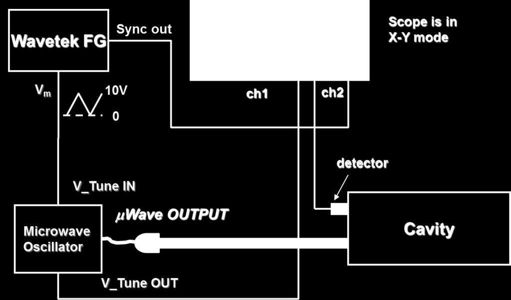
18 1. Oscilloscope should run in X-Y mode 2. To plot the I(f) dependence you have to download both Ch1 and Ch2 data 3. Use triangular waveform as a voltage applied to modulation input of the oscillator 4. Use a proper time scale setting on the scope which could estimated from scanning frequency 5. Apply the calibration equation to calculate the frequency of the oscillator from the modulation voltage G 4/3/2017 f V mod 18

19 Voltage tunable oscillator ZX a- S+ from 4/3/
20 FM Calibration for microwave oscillator 4/3/
21 4/3/
22 By changing of the coupling between oscillator and cavity we can control the quality factor of the cavity resonance but in the same time we changing the power delivered to the cavity 4/3/

23 Detector B field While in resonance: turn orientation of the input loop from the vertical direction in 10 o steps to 360 o. Read cavity detector. 4/3/
24 12 10 I (ma) Experimental result. Fitted to A (cos( + )) n + A grad) 4/3/
25 Presence of dielectric reduces length of cavity at a given resonance frequency ω 0. This effect grows with the electric field strength E y. (0) Without dielectric the cavity length at resonace is c 0. (1) Place dielectric into cavity and move in 0.5cm steps, l i. (2) At each place tune plunger to resonance and record c i. (3) Plot c i = c 0 -c i versus l i : this measures now E y vs l! 4/3/

26 TE 102 X Y Z Courtesy of P. Debevec 4/3/
27 Quality factor (TE 101 mode) of unloaded cavity can be calculated as: Q 2 2 abc a c b a c ac a c is the skin depth at frequency 0 2 / c b resistivity of the cavity material r 0 0 4x10 7 a 4/3/
28 For red brass =6x10⁻⁸ m 4x / 2.25x10⁻⁶ m a=7.22cm, b=3.42 cm, c=6.91cm (TE 101 ) Q 2 2 abc a c 2b a c ac a c c b Q 0 ~7700 a 4/3/

29 q =90 0 -q 4/3/
30 4? Matthew Stupca Longxiang Zhang I (A) 2 (100) (110) (111) (200)(210) (211) (220) (300) (degree) 4/3/


31 Second order reflection? Lloyd s mirror effect 4/3/
MAHAVEER INSTITUTE OF SCIENCE & TECHNOLOGY. Microwave and Digital Communications Lab. Department Of Electronics and Communication Engineering
 MAHAVEER INSTITUTE OF SCIENCE & TECHNOLOGY Microwave and Digital Communications Lab Department Of Electronics and Communication Engineering MICROWAVE ENGINEERING LAB List of Experiments: 1.Reflex Klystron
MICROWAVE AND RADAR LAB (EE-322-F) LAB MANUAL VI SEMESTER
 LAB MANUAL VI SEMESTER") 1 MICROWAVE AND RADAR LAB (EE-322-F) MICROWAVE AND RADAR LAB (EE-322-F) LAB MANUAL VI SEMESTER RAO PAHALD SINGH GROUP OF INSTITUTIONS BALANA(MOHINDERGARH)123029 Department Of Electronics and Communication
1 MICROWAVE AND RADAR LAB (EE-322-F) MICROWAVE AND RADAR LAB (EE-322-F) LAB MANUAL VI SEMESTER RAO PAHALD SINGH GROUP OF INSTITUTIONS BALANA(MOHINDERGARH)123029 Department Of Electronics and Communication
7. Experiment K: Wave Propagation
 7. Experiment K: Wave Propagation This laboratory will be based upon observing standing waves in three different ways, through coaxial cables, in free space and in a waveguide. You will also observe some
MULTIMEDIA UNIVERSITY FACULTY OF ENGINEERING LAB SHEET
 MULTIMEDIA UNIVERSITY FACULTY OF ENGINEERING LAB SHEET ELECTROMAGNETIC THEORY EMF016 MW1 MICROWAVE FREQUENCY AND SWR MEASUREMENTS EM Theory Faculty of Engineering, Multimedia University 1 EXPERIMENT MW1:
DESIGN AND FABRICATION OF CAVITY RESONATORS
 &2@?%3 DESIGN AND FABRICATION OF CAVITY RESONATORS CHAPTER 3 DESIGN AND FABRICATION OFCAVITY RESONATORS 3.1 Introduction In the cavity perturbation techniques, generally rectangular or cylindrical waveguide
(i) Determine the admittance parameters of the network of Fig 1 (f) and draw its - equivalent circuit.
 Determine the admittance parameters of the network of Fig 1 (f) and draw its - equivalent circuit.") I.E.S-(Conv.)-1995 ELECTRONICS AND TELECOMMUNICATION ENGINEERING PAPER - I Some useful data: Electron charge: 1.6 10 19 Coulomb Free space permeability: 4 10 7 H/m Free space permittivity: 8.85 pf/m Velocity
I.E.S-(Conv.)-1995 ELECTRONICS AND TELECOMMUNICATION ENGINEERING PAPER - I Some useful data: Electron charge: 1.6 10 19 Coulomb Free space permeability: 4 10 7 H/m Free space permittivity: 8.85 pf/m Velocity
Waveguides. Metal Waveguides. Dielectric Waveguides
 Waveguides Waveguides, like transmission lines, are structures used to guide electromagnetic waves from point to point. However, the fundamental characteristics of waveguide and transmission line waves
RAJIV GANDHI COLLEGE OF ENGINEERING AND TECHNOLOGY Kirumampakkam,Puducherry DEPARTMENT OF ELECTRONICS AND COMMUNICATION ENGINEERING
 RAJIV GANDHI COLLEGE OF ENGINEERING AND TECHNOLOGY Kirumampakkam,Puducherry-607402 DEPARTMENT OF ELECTRONICS AND COMMUNICATION ENGINEERING QUESTION BANK FOR EC T55 - TRANSMISSION LINES AND WAVEGUIDES G.LAXMINARAYANAN,
Experiment-4 Study of the characteristics of the Klystron tube
 Experiment-4 Study of the characteristics of the Klystron tube OBJECTIVE To study the characteristics of the reflex Klystron tube and to determine the its electronic tuning range EQUIPMENTS Klystron power
EE 3324 Electromagnetics Laboratory
 EE 3324 Electromagnetics Laboratory Experiment #11 Microwave Systems 1. Objective The objective of Experiment #11 is to investigate microwave systems and associated measurement techniques. A precision
Dhanalakshmi College of Engineering Department of ECE EC6701 RF and Microwave Engineering Unit 5 Microwave Measurements Part A
 Dhanalakshmi College of Engineering Department of ECE EC6701 RF and Microwave Engineering Unit 5 Microwave Measurements Part A 1. What is the principle by which high power measurements could be done by
Lab 1: Pulse Propagation and Dispersion
 ab 1: Pulse Propagation and Dispersion NAME NAME NAME Introduction: In this experiment you will observe reflection and transmission of incident pulses as they propagate down a coaxial transmission line
EC Transmission Lines And Waveguides
 EC6503 - Transmission Lines And Waveguides UNIT I - TRANSMISSION LINE THEORY A line of cascaded T sections & Transmission lines - General Solution, Physical Significance of the Equations 1. Define Characteristic
Useful general references for this experiment are Cheng [1], and Ramo et al [2].
![Useful general references for this experiment are Cheng [1], and Ramo et al [2].](/thumbs/74/70212276.jpg "Useful general references for this experiment are Cheng [1], and Ramo et al [2].") Experiment 7. Wave Propagation Updated RWH 21 August 2012 1 Aim In this experiment you will measure the radiation pattern of a half-wave dipole antenna, determine the resonant frequencies of a microwave
Experiment 7. Wave Propagation Updated RWH 21 August 2012 1 Aim In this experiment you will measure the radiation pattern of a half-wave dipole antenna, determine the resonant frequencies of a microwave
MICROWAVE MICROWAVE TRAINING BENCH COMPONENT SPECIFICATIONS:
 Microwave section consists of Basic Microwave Training Bench, Advance Microwave Training Bench and Microwave Communication Training System. Microwave Training System is used to study all the concepts of
Lab 12 Microwave Optics.
 b Lab 12 Microwave Optics. CAUTION: The output power of the microwave transmitter is well below standard safety levels. Nevertheless, do not look directly into the microwave horn at close range when the
R.K.YADAV. 2. Explain with suitable sketch the operation of two-cavity Klystron amplifier. explain the concept of velocity and current modulations.
 Question Bank DEPARTMENT OF ELECTRONICS AND COMMUNICATION SUBJECT- MICROWAVE ENGINEERING(EEC-603) Unit-III 1. What are the high frequency limitations of conventional tubes? Explain clearly. 2. Explain
10 GHz Microwave Link
 10 GHz Microwave Link Project Project Objectives System System Functionality Testing Testing Procedures Cautions and Warnings Problems Encountered Recommendations Conclusion PROJECT OBJECTIVES Implement
Experiment 2 Determining the Capacitive Reactance of a Capacitor in an AC Circuit
 Experiment 2 Determining the apacitive eactance of a apacitor in an A ircuit - Objects of the experiments: a- Investigating the voltage and the current at a capacitor in an A circuit b- Observing the phase
Specification. CTR 2 ESD calibration target
 Specification CTR 2 ESD calibration target IEC 61000-4-2 IEC 61000-4-2 77B/378/CDV ISO CD 10605 N1347 The CTR 2 is a coaxial current target to monitor Electro Static Discharges as required in the draft
Microwave Circuit Design and Measurements Lab. INTRODUCTION TO MICROWAVE MEASUREMENTS: DETECTION OF RF POWER AND STANDING WAVES Lab #2
 EE 458/558 Microwave Circuit Design and Measurements Lab INTRODUCTION TO MICROWAVE MEASUREMENTS: DETECTION OF RF POWER AND STANDING WAVES Lab #2 The purpose of this lab is to gain a basic understanding
EC TRANSMISSION LINES AND WAVEGUIDES TRANSMISSION LINES AND WAVEGUIDES
 TRANSMISSION LINES AND WAVEGUIDES UNIT I - TRANSMISSION LINE THEORY 1. Define Characteristic Impedance [M/J 2006, N/D 2006] Characteristic impedance is defined as the impedance of a transmission line measured
Detection of Lower Hybrid Waves on Alcator C-Mod with Phase Contrast Imaging Using Electro-Optic Modulators
 Detection of Lower Hybrid Waves on Alcator C-Mod with Phase Contrast Imaging Using Electro-Optic Modulators K. Arai, M. Porkolab, N. Tsujii, P. Koert, R. Parker, P. Woskov, S. Wukitch MIT Plasma Science
Dinesh Micro Waves & Electronics
 MICROWAVE TRAINING KITS Dinesh Microwaves and Electronics manufacturers of three centimeter waveguidetraining system to provide users an in depth training on microwave waveguide device. The training kit
ENE324. Microwave experiments
 ENE324 Microwave experiments Gunn diodes are fabricated from a single piece of n-type semiconductor. The most common materials are gallium Arsenide, GaAs and Indium Phosphide,InP. However other materials
Experiment 19. Microwave Optics 1
 Experiment 19 Microwave Optics 1 1. Introduction Optical phenomena may be studied at microwave frequencies. Using a three centimeter microwave wavelength transforms the scale of the experiment. Microns
Microwave and optical systems Introduction p. 1 Characteristics of waves p. 1 The electromagnetic spectrum p. 3 History and uses of microwaves and
 Microwave and optical systems Introduction p. 1 Characteristics of waves p. 1 The electromagnetic spectrum p. 3 History and uses of microwaves and optics p. 4 Communication systems p. 6 Radar systems p.
Lecture - 14 Microwave Resonator
 Basic Building Blocks of Microwave Engineering Prof Amitabha Bhattacharya Department of Electronics and Communication Engineering Indian Institute of Technology, Kharagpur Lecture - 14 Microwave Resonator
Microwave Magnetics. Graduate Course Electrical Engineering (Communications) 2 nd Semester, Sharif University of Technology
 2 nd Semester, Sharif University of Technology") Microwave Magnetics Graduate Course Electrical Engineering (Communications) 2 nd Semester, 389-39 Sharif University of Technology General information Contents of lecture 8: Waveguide resonators General
Microwave Magnetics Graduate Course Electrical Engineering (Communications) 2 nd Semester, 389-39 Sharif University of Technology General information Contents of lecture 8: Waveguide resonators General
EC 1402 Microwave Engineering
 SHRI ANGALAMMAN COLLEGE OF ENGINEERING & TECHNOLOGY (An ISO 9001:2008 Certified Institution) SIRUGANOOR,TRICHY-621105. DEPARTMENT OF ELECTRONICS AND COMMUNICATION ENGINEERING EC 1402 Microwave Engineering
Integrators, differentiators, and simple filters
 BEE 233 Laboratory-4 Integrators, differentiators, and simple filters 1. Objectives Analyze and measure characteristics of circuits built with opamps. Design and test circuits with opamps. Plot gain vs.
St.MARTIN S ENGINEERING COLLEGE Dhulapally, Secunderabad
 St.MARTIN S ENGINEERING COLLEGE Dhulapally, Secunderabad 500014. Department of Electronics and Communication Engineering SUB: MICROWAVE ENGINEERING SECTION: ECE IV A & B NAME OF THE FACULTY: S RAVI KUMAR,T.SUDHEER
PHYS2090 OPTICAL PHYSICS Laboratory Microwaves
 PHYS2090 OPTICAL PHYSICS Laboratory Microwaves Reference Hecht, Optics, (Addison-Wesley) 1. Introduction Interference and diffraction are commonly observed in the optical regime. As wave-particle duality
Microwave Resonance in a Waveguide System. Abstract
 Microwave Resonance in a Waveguide System Peter M. Marchetto Bioacoustics Research Program, Cornell Lab of Ornithology, Cornell University, Ithaca, NY Abstract A waveguide system in the microwave X-band
New SLED 3 system for Multi-mega Watt RF compressor. Chen Xu, Juwen Wang, Sami Tantawi
 New SLED 3 system for Multi-mega Watt RF compressor Chen Xu, Juwen Wang, Sami Tantawi SLAC National Accelerator Laboratory, Stanford University, Stanford, CA 94309, USA Electronic address: chenxu@slac.stanford.edu
Exercise 1-3. Radar Antennas EXERCISE OBJECTIVE DISCUSSION OUTLINE DISCUSSION OF FUNDAMENTALS. Antenna types
 Exercise 1-3 Radar Antennas EXERCISE OBJECTIVE When you have completed this exercise, you will be familiar with the role of the antenna in a radar system. You will also be familiar with the intrinsic characteristics
COAXIAL / CIRCULAR HORN ANTENNA FOR A STANDARD
 COAXIAL / CIRCULAR HORN ANTENNA FOR 802.11A STANDARD Petr Všetula Doctoral Degree Programme (1), FEEC BUT E-mail: xvsetu00@stud.feec.vutbr.cz Supervised by: Zbyněk Raida E-mail: raida@feec.vutbr.cz Abstract:
R. J. Jones College of Optical Sciences OPTI 511L Fall 2017
 R. J. Jones College of Optical Sciences OPTI 511L Fall 2017 Active Modelocking of a Helium-Neon Laser The generation of short optical pulses is important for a wide variety of applications, from time-resolved
EE 3324 Electromagnetics Laboratory
 EE 3324 Electromagnetics Laboratory Experiment #10 Microstrip Circuits and Measurements 1. Objective The objective of Experiment #8 is to investigate the application of microstrip technology. A precision
9. Microwaves. 9.1 Introduction. Safety consideration
 MW 9. Microwaves 9.1 Introduction Electromagnetic waves with wavelengths of the order of 1 mm to 1 m, or equivalently, with frequencies from 0.3 GHz to 0.3 THz, are commonly known as microwaves, sometimes
Department of Electrical Engineering University of North Texas
 Name: Shabuktagin Photon Khan UNT ID: 10900555 Instructor s Name: Professor Hualiang Zhang Course Name: Antenna Theory and Design Course ID: EENG 5420 Email: khan.photon@gmail.com Department of Electrical
Microwave Optics. Department of Physics & Astronomy Texas Christian University, Fort Worth, TX. January 16, 2014
 Microwave Optics Department of Physics & Astronomy Texas Christian University, Fort Worth, TX January 16, 2014 1 Introduction Optical phenomena may be studied at microwave frequencies. Visible light has
Microwave Technology Training Systems
 Microwave Technology Training Systems LabVolt Series Datasheet Festo Didactic en 220 V - 50 Hz 07/2018 Table of Contents General Description 2 System courseware 2 Topic Coverage 3 Features & Benefits 3
Introduction. Equipment
 MICROWAVE OPTICS Microwave Optics Introduction There are many advantages to studying optical phenomena at microwave frequencies. Using a 2.85 centimeter microwave wavelength transforms the scale of the
INVESTIGATION OF THE LONGITUDINAL FIELD COMPONENT INSIDE THE GTEM 1750
 INVESTIGATION OF THE LONGITUDINAL FIELD COMPONENT INSIDE THE GTEM 1750 H.M. LOOE, Y. HUANG B.G. LOADER, M.J. ALEXANDER, W. LIANG The University of Liverpool, UK Introduction GTEM (Gigahertz Traverse Electromagnetic)
Photograph of the rectangular waveguide components
 Waveguides Photograph of the rectangular waveguide components BACKGROUND A transmission line can be used to guide EM energy from one point (generator) to another (load). A transmission line can support
The Principle V(SWR) The Result. Mirror, Mirror, Darkly, Darkly
 The Result. Mirror, Mirror, Darkly, Darkly") The Principle V(SWR) The Result Mirror, Mirror, Darkly, Darkly 1 Question time!! What do you think VSWR (SWR) mean to you? What does one mean by a transmission line? Coaxial line Waveguide Water pipe Tunnel
The Principle V(SWR) The Result Mirror, Mirror, Darkly, Darkly 1 Question time!! What do you think VSWR (SWR) mean to you? What does one mean by a transmission line? Coaxial line Waveguide Water pipe Tunnel
EP603 Microwave Devices
 EP603 Microwave Devices TOPIC 3 MICROWAVE MEASUREMENTS Lesson Learning outcomes 1. Draw the block diagram of instrument in microwave testing 2. Explain the function of each block and overall measurement
A VARACTOR-TUNABLE HIGH IMPEDANCE SURFACE FOR ACTIVE METAMATERIAL ABSORBER
 Progress In Electromagnetics Research C, Vol. 43, 247 254, 2013 A VARACTOR-TUNABLE HIGH IMPEDANCE SURFACE FOR ACTIVE METAMATERIAL ABSORBER Bao-Qin Lin *, Shao-Hong Zhao, Qiu-Rong Zheng, Meng Zhu, Fan Li,
MICROSTRIP AND WAVEGUIDE PASSIVE POWER LIMITERS WITH SIMPLIFIED CONSTRUCTION
 Journal of Microwaves and Optoelectronics, Vol. 1, No. 5, December 1999. 14 MICROSTRIP AND WAVEGUIDE PASSIVE POWER IMITERS WITH SIMPIFIED CONSTRUCTION Nikolai V. Drozdovski & ioudmila M. Drozdovskaia ECE
Loop and Slot Antennas
 Loop and Slot Antennas Prof. Girish Kumar Electrical Engineering Department, IIT Bombay gkumar@ee.iitb.ac.in (022) 2576 7436 Loop Antenna Loop antennas can have circular, rectangular, triangular or any
PHYSICS WORKSHEET CLASS : XII. Topic: Alternating current
 PHYSICS WORKSHEET CLASS : XII Topic: Alternating current 1. What is mean by root mean square value of alternating current? 2. Distinguish between the terms effective value and peak value of an alternating
3.003 Lab 3 Part A. Measurement of Speed of Light
 3.003 Lab 3 Part A. Measurement of Speed of Light Objective: To measure the speed of light in free space Experimental Apparatus: Feb. 18, 2010 Due Mar. 2, 2010 Components: 1 Laser, 4 mirrors, 1 beam splitter
Waveguides GATE Problems
 Waveguides GATE Problems One Mark Questions. The interior of a 20 20 cm cm rectangular waveguide is completely 3 4 filled with a dielectric of r 4. Waves of free space wave length shorter than..can be
A. Kumar and S. Sharma Department of Electronics and Communication Engineering S. D. D. Institute of Engineering and Technology Barwala, India
 Progress In Electromagnetics Research, PIER 69, 47 54, 2007 MEASUREMENT OF DIELECTRIC CONSTANT AND LOSS FACTOR OF THE DIELECTRIC MATERIAL AT MICROWAVE FREQUENCIES A. Kumar and S. Sharma Department of Electronics
Microwave Engineering Third Edition
 Microwave Engineering Third Edition David M. Pozar University of Massachusetts at Amherst WILEY John Wiley & Sons, Inc. ELECTROMAGNETIC THEORY 1 1.1 Introduction to Microwave Engineering 1 Applications
LRL Model 550B-SS Microwave Training Kit
 MICROWAVES FOR EVERYONE LRL Model 550B-SS Microwave Training Kit Microwave Training Kit 5 Experiments I-95 Industrial Park 651 Winks Lane Bensalem, PA 1900 800.53.399 15.638.1100 3rd edition INITIAL SET-UP
MICROWAVE COMMUNICATION LAB
 SRI SUKHMANI INSTITUTE OF ENGINEERING AND TECHNOLOGY, DERA BASSI (MOHALI) MICROWAVE COMMUNICATION LAB Laboratory Manual SRI SUKHMANI INSTITUTE OF ENGINEERING & TECHNOLOGY DERA BASSI DEPARTMENT: ELECTRONICS
Tuning. Elements ROHS COMPLIANT
 DESCRIPTION Economical means of introducing a variable reactance to microwave circuits such as waveguides, filters, cavities and other resonant structures High resolution tuning Self-locking constant torque
QUESTION BANK SUB. NAME: RF & MICROWAVE ENGINEERING SUB. CODE: EC 2403 BRANCH/YEAR/: ECE/IV UNIT 1 TWO PORT RF NETWORKS- CIRCUIT REPRESENTATION
 QUESTION BANK SUB. NAME: RF & MICROWAVE ENGINEERING SUB. CODE: EC 2403 SEM: VII BRANCH/YEAR/: ECE/IV UNIT 1 TWO PORT RF NETWORKS- CIRCUIT REPRESENTATION 1. What is RF? 2. What is an RF tuner? 3. Define
ECSE 352: Electromagnetic Waves
 December 2008 Final Examination ECSE 352: Electromagnetic Waves 09:00 12:00, December 15, 2008 Examiner: Zetian Mi Associate Examiner: Andrew Kirk Student Name: McGill ID: Instructions: This is a CLOSED
INSTITUTE OF AERONAUTICAL ENGINEERING (Autonomous) Dundigal, Hyderabad
 Dundigal, Hyderabad") INSTITUTE OF AERONAUTICAL ENGINEERING (Autonomous) Dundigal, Hyderabad - 500 043 ELECTRONICS AND COMMUNICATION ENGINEERING TUTORIAL BANK Name : MICROWAVE ENGINEERING Code : A70442 Class : IV B. Tech I
INSTITUTE OF AERONAUTICAL ENGINEERING (Autonomous) Dundigal, Hyderabad - 500 043 ELECTRONICS AND COMMUNICATION ENGINEERING TUTORIAL BANK Name : MICROWAVE ENGINEERING Code : A70442 Class : IV B. Tech I
Frequency Tunable Low-Cost Microwave Absorber for EMI/EMC Application
 Progress In Electromagnetics Research Letters, Vol. 74, 47 52, 2018 Frequency Tunable Low-Cost Microwave Absorber for EMI/EMC Application Gobinda Sen * and Santanu Das Abstract A frequency tunable multi-layer
Overview of experiments and projects
 Overview of experiments and projects Pathways: Experiments Experiment EE ECE Media Eng D: Op Amps 1 1 F: Digital Communications 1 1 1 S: Pulses and Bandwidth 1 J: Transformers 1 K: Wave Propagation 1 Software
Fundamentals of Electromagnetics With Engineering Applications by Stuart M. Wentworth Copyright 2005 by John Wiley & Sons. All rights reserved.
 Figure 7-1 (p. 339) Non-TEM mmode waveguide structures include (a) rectangular waveguide, (b) circular waveguide., (c) dielectric slab waveguide, and (d) fiber optic waveguide. Figure 7-2 (p. 340) Cross
sue-m-147 October 1965
 sue-m-147 October 1965 A perturbation measurement technique has been developed at Stanford University which determines the phase and field strength at a point inside a microwave structure by measuring
arxiv:physics/ v1 [physics.optics] 28 Sep 2005
![arxiv:physics/ v1 [physics.optics] 28 Sep 2005](/thumbs/91/105523130.jpg "arxiv:physics/ v1 [physics.optics] 28 Sep 2005") Near-field enhancement and imaging in double cylindrical polariton-resonant structures: Enlarging perfect lens Pekka Alitalo, Stanislav Maslovski, and Sergei Tretyakov arxiv:physics/0509232v1 [physics.optics]
Near-field enhancement and imaging in double cylindrical polariton-resonant structures: Enlarging perfect lens Pekka Alitalo, Stanislav Maslovski, and Sergei Tretyakov arxiv:physics/0509232v1 [physics.optics]
Physics 2310 Lab #2 Speed of Sound & Resonance in Air
 Physics 2310 Lab #2 Speed of Sound & Resonance in Air Objective: The objectives of this experiment are a) to measure the speed of sound in air, and b) investigate resonance within air. Apparatus: Pasco
GUJARAT TECHNOLOGICAL UNIVERSITY, AHMEDABAD, GUJARAT COURSE CURRICULUM COURSE TITLE: MICROWAVE & RADAR ENGINEERING (COURSE CODE: )
") GUJARAT TECHNOLOGICAL UNIVERSITY, AHMEDABAD, GUJARAT COURSE CURRICULUM COURSE TITLE: MICROWAVE & RADAR ENGINEERING (COURSE CODE: 3351103) Diploma Programme in which this course is offered Electronics and
GUJARAT TECHNOLOGICAL UNIVERSITY, AHMEDABAD, GUJARAT COURSE CURRICULUM COURSE TITLE: MICROWAVE & RADAR ENGINEERING (COURSE CODE: 3351103) Diploma Programme in which this course is offered Electronics and
Microwave Diffraction and Interference
 Microwave Diffraction and Interference Department of Physics Ryerson University rev.2014 1 Introduction The object of this experiment is to observe interference and diffraction of microwave radiation,
MICROWAVE AND RADAR ENGINEERING (EE 322 F) LIST OF EXPERIMENTS. S.NO. NAME OF THE EXPERIMENT Page No.
 LIST OF EXPERIMENTS. S.NO. NAME OF THE EXPERIMENT Page No.") LIST OF EXPERIMENTS S.NO. NAME OF THE EXPERIMENT Page No. 1 To study wave guide components. 1-3 2 To study the characteristics of Gunn oscillator &Gun diode as 4-6 modulated source. 3 Study of wave guide
LIST OF EXPERIMENTS S.NO. NAME OF THE EXPERIMENT Page No. 1 To study wave guide components. 1-3 2 To study the characteristics of Gunn oscillator &Gun diode as 4-6 modulated source. 3 Study of wave guide
Progress In Electromagnetics Research, Vol. 113, , 2011
 Progress In Electromagnetics Research, Vol. 113, 143 160, 2011 BROADBAND COMPLEX PERMITTIVITY MEASUREMENT OF LOW LOSS MATERIALS OVER LARGE TEMPERATURE RANGES BY STRIPLINE RESONATOR CAVITY USING SEGMENTATION
Experiment 1 Alternating Current with Coil and Ohmic Resistors
 Experiment Alternating Current with Coil and Ohmic esistors - Objects of the experiment - Determining the total impedance and the phase shift in a series connection of a coil and a resistor. - Determining
University of Manitoba Department of Electrical & Computer Engineering. ECE 4600 Group Design Project. Progress Report. Microwave Imaging.
 University of Manitoba Department of Electrical & Computer Engineering ECE 4600 Group Design Project Progress Report Microwave Imaging by Group 12 Steven Brown Trevor Ingelbeen Brett Trombo Bryce O Donnel
Broadside - Coupled Split Ring Resonator (BC-SRR) Metamaterial-Like Slow-Wave Structure. Sabahattin C. Yurt
 Metamaterial-Like Slow-Wave Structure. Sabahattin C. Yurt") Department of Electrical & Computer Engineering MURI Teleconference Broadside - Coupled Split Ring Resonator (BC-SRR) Metamaterial-Like Slow-Wave Structure Sabahattin C. Yurt cyurt@unm.edu Sarita Prasad
Department of Electrical & Computer Engineering MURI Teleconference Broadside - Coupled Split Ring Resonator (BC-SRR) Metamaterial-Like Slow-Wave Structure Sabahattin C. Yurt cyurt@unm.edu Sarita Prasad
Experiment VI: The LRC Circuit and Resonance
 Experiment VI: The ircuit and esonance I. eferences Halliday, esnick and Krane, Physics, Vol., 4th Ed., hapters 38,39 Purcell, Electricity and Magnetism, hapter 7,8 II. Equipment Digital Oscilloscope Digital
Measurement in Coax 84
 HEWLETT lpl PACKARD SXA/R application note Measurement in Coax 84 -\B 6T - Slotted Line Accuracy - 2 to 1B GHz For more information, call your local HP Sales Office or East (201) 265-5000 Midwest (312)
Lab Manual Experiment No. 2
 Lab Manual Experiment No. 2 Aim of Experiment: Observe the transient phenomenon of terminated coaxial transmission lines in order to study their time domain behavior. Requirement: You have to install a
Lec7 Transmission Lines and waveguides (II)
") Lec7 Transmission Lines and waveguides (II) 3.4 CIRCULAR WAVEGUIDE A hollow, round metal pipe also supports TE and TM waveguide modes. we can derive the cylindrical components of the transverse fields
Lec7 Transmission Lines and waveguides (II) 3.4 CIRCULAR WAVEGUIDE A hollow, round metal pipe also supports TE and TM waveguide modes. we can derive the cylindrical components of the transverse fields
Lecture 16 Microwave Detector and Switching Diodes
 Basic Building Blocks of Microwave Engineering Prof. Amitabha Bhattacharya Department of Electronics and Communication Engineering Indian Institute of Technology, Kharagpur Lecture 16 Microwave Detector
Microwave Circuit Analysis and Amplifier Design
 Microwave Circuit Analysis and Amplifier Design SAMUEL Y. LIAO Professor of Electrical Engineering California State University, Fresno PRENTICE-HALL, INC., Englewood Cliffs, New Jersey 07632 Contents PREFACE
OF MICROWAVE OSCILLATORS
 RECENT DEVELOPMENTS IN FREQUENCY STABILIZATION RECENT DEVELOPMENTS IN FREQUENCY STABILIZATION OF MICROWAVE OSCILLATORS W. G. TULLER, W. C. GALLOWAY, AND F. P. ZAFFARANO TECHNICAL REPORT NO. 53 November
Exercise 2: Demodulation (Quadrature Detector)
") Analog Communications Angle Modulation and Demodulation Exercise 2: Demodulation (Quadrature Detector) EXERCISE OBJECTIVE When you have completed this exercise, you will be able to explain demodulation
Analog Communications Angle Modulation and Demodulation Exercise 2: Demodulation (Quadrature Detector) EXERCISE OBJECTIVE When you have completed this exercise, you will be able to explain demodulation
LOW NOISE GHZ RECEIVERS USING SINGLE-DIODE HARMONIC MIXERS
 First International Symposium on Space Terahertz Technology Page 399 LOW NOISE 500-700 GHZ RECEIVERS USING SINGLE-DIODE HARMONIC MIXERS Neal R. Erickson Millitech Corp. P.O. Box 109 S. Deerfield, MA 01373
a) Basic unit of an ideal transmission line b) an ideal transmission line
 Basic unit of an ideal transmission line b) an ideal transmission line") Pulses in cables eferences: H.J. Pain: The Physics of ibrations and Waves, 5 th ed., Wiley, Chapter 7 (Waves in Transmission lines) T.. Kuphaldt: Lessons in Electric Circuits, olume AC, Chapter 4 (Transmission
Pulses in cables eferences: H.J. Pain: The Physics of ibrations and Waves, 5 th ed., Wiley, Chapter 7 (Waves in Transmission lines) T.. Kuphaldt: Lessons in Electric Circuits, olume AC, Chapter 4 (Transmission
Lecture #3 Microstrip lines
 November 2014 Ahmad El-Banna Benha University Faculty of Engineering at Shoubra Post-Graduate ECE-601 Active Circuits Lecture #3 Microstrip lines Instructor: Dr. Ahmad El-Banna Agenda Striplines Forward
Lab E5: Filters and Complex Impedance
 E5.1 Lab E5: Filters and Complex Impedance Note: It is strongly recommended that you complete lab E4: Capacitors and the RC Circuit before performing this experiment. Introduction Ohm s law, a well known
Part 1: Standing Waves - Measuring Wavelengths
 Experiment 7 The Microwave experiment Aim: This experiment uses microwaves in order to demonstrate the formation of standing waves, verifying the wavelength λ of the microwaves as well as diffraction from
MICROWAVE ENGINEERING-II. Unit- I MICROWAVE MEASUREMENTS
 MICROWAVE ENGINEERING-II Unit- I MICROWAVE MEASUREMENTS 1. Explain microwave power measurement. 2. Why we can not use ordinary diode and transistor in microwave detection and microwave amplification? 3.
Microwave Devices and Circuit Design
 Microwave Devices and Circuit Design Ganesh Prasad Srivastava Vijay Laxmi Gupta MICROWAVE DEVICES and CIRCUIT DESIGN GANESH PRASAD SRIVASTAVA Professor (Retired) Department of Electronic Science University
Microwave Engineering
 Microwave Circuits 1 Microwave Engineering 1. Microwave: 300MHz ~ 300 GHz, 1 m ~ 1mm. a. Not only apply in this frequency range. The real issue is wavelength. Historically, as early as WWII, this is the
INTERFERENCE OF SOUND WAVES
 01/02 Interference - 1 INTERFERENCE OF SOUND WAVES The objectives of this experiment are: To measure the wavelength, frequency, and propagation speed of ultrasonic sound waves. To observe interference
Physics 476LW. Advanced Physics Laboratory - Microwave Optics
 Physics 476LW Advanced Physics Laboratory Microwave Radiation Introduction Setup The purpose of this lab is to better understand the various ways that interference of EM radiation manifests itself. However,
Experimental Study on W-Band ( GHz) Oversized Surface Wave Oscillator Driven by Weakly Relativistic Electron Beams )
 Oversized Surface Wave Oscillator Driven by Weakly Relativistic Electron Beams )") Experimental Study on W-Band (75-110 GHz) Oversized Surface Wave Oscillator Driven by Weakly Relativistic Electron Beams ) Min Thu SAN, Kazuo OGURA, Kiyoyuki YAMBE, Yuta ANNAKA, Shaoyan GONG, Jun KAWAMURA,
Experimental Study on W-Band (75-110 GHz) Oversized Surface Wave Oscillator Driven by Weakly Relativistic Electron Beams ) Min Thu SAN, Kazuo OGURA, Kiyoyuki YAMBE, Yuta ANNAKA, Shaoyan GONG, Jun KAWAMURA,
ELECTROMAGNETIC WAVES AND ANTENNAS
 Syllabus ELECTROMAGNETIC WAVES AND ANTENNAS - 83888 Last update 20-05-2015 HU Credits: 4 Degree/Cycle: 1st degree (Bachelor) Responsible Department: Applied Phyisics Academic year: 1 Semester: 2nd Semester
The University of Jordan Mechatronics Engineering Department Electronics Lab.( ) Experiment 1: Lab Equipment Familiarization
 Experiment 1: Lab Equipment Familiarization") The University of Jordan Mechatronics Engineering Department Electronics Lab.(0908322) Experiment 1: Lab Equipment Familiarization Objectives To be familiar with the main blocks of the oscilloscope and
The University of Jordan Mechatronics Engineering Department Electronics Lab.(0908322) Experiment 1: Lab Equipment Familiarization Objectives To be familiar with the main blocks of the oscilloscope and
Magnetism and Induction
 Magnetism and Induction Before the Lab Read the following sections of Giancoli to prepare for this lab: 27-2: Electric Currents Produce Magnetism 28-6: Biot-Savart Law EXAMPLE 28-10: Current Loop 29-1:
Analysis of an air-spaced patch antenna near 1800 MHz
 Marquette University e-publications@marquette Master's Theses (2009 -) Dissertations, Theses, and Professional Projects Analysis of an air-spaced patch antenna near 1800 MHz Hermine Nathalie Akouemo Kengmo
INTRODUCTION TO AC FILTERS AND RESONANCE
 AC Filters & Resonance 167 Name Date Partners INTRODUCTION TO AC FILTERS AND RESONANCE OBJECTIVES To understand the design of capacitive and inductive filters To understand resonance in circuits driven
Industrial Electricity. Answer questions and/or record measurements in the spaces provided.
 Industrial Electricity Lab 10: Building a Basic Power Supply ame Due Friday, 3/16/18 Answer questions and/or record measurements in the spaces provided. Measure resistance (impedance actually) on each