Lec7 Transmission Lines and waveguides (II)
|
|
|
- Sheryl Todd
- 5 years ago
- Views:
Transcription
1 Lec7 Transmission Lines and waveguides (II)

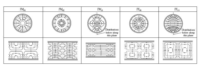
2 3.4 CIRCULAR WAVEGUIDE A hollow, round metal pipe also supports TE and TM waveguide modes. we can derive the cylindrical components of the transverse fields from the longitudinal components as
3 TE Modes For TE modes, Ez = 0, and Hz is a solution to the wave equation, apply the method of separation of variables.
4 Kφ must be an integer, n. which is recognized as Bessel s differential equation. The solution is
5 The solution for hz can then be simplified to We must still determine the cutoff wave number kc, which we can do by enforcing the boundary condition that Etan = 0 on the waveguide wall. For Eφ to vanish at ρ = a, we must have
6 Values of p nm are given in mathematical tables; the cutoff wave number k cnm = p nm /a, where n refers to the number of circumferential (φ) variations and m refers to the number of radial (ρ) variations. The propagation constant of the TE nm mode is with a cutoff frequency of
7 The first TE mode is the TE 11 mode since it has the smallest p nm. Because m 1, there is no TE10 mode, but there is a TE 01 mode. The transverse field components are, The wave impedance is
8 A and B control the amplitude of the sin nφ and cos nφ terms, which are independent. The actual amplitudes of these terms will depend on the excitation of the waveguide. Now consider the dominant TE11 mode with an excitation such that B = 0. The fields can be written as
9 The power flow down the guide can be computed as which is seen to be nonzero only when β is real, corresponding to a propagating mode.
10 Attenuation due to dielectric loss is The attenuation due to a lossy waveguide conductor can be found by computing the power loss per unit length of guide: The attenuation constant is then
11 TM Modes we must solve for Ez from the wave equation in cylindrical coordinates: the general solutions the boundary conditions then
12 The propagation constant of the TMnm mode is the cutoff frequency is the first TM mode to propagate is the TM 01 mode, with p 01 =
13 Since p 01 = is greater than the TE11 mode is the dominant mode of the circular waveguide. m 1, so there is no TM 10 mode. the transverse fields can be derived as The wave impedance is
14 the attenuation of the TE 01 mode decreases to a very small value with increasing frequency. This property makes the TE01 mode of interest for low-loss transmission over long distances. Unfortunately, this mode is not the dominant mode of the circular waveguide, so in practice power can be lost from the TE01 mode to lower order propagating modes.
15
16
17
18 EXAMPLE 3.2 CHARACTERISTICS OF A CIRCULAR WAVEGUIDE Find the cutoff frequencies of the first two propagating modes of a Teflon-filled circular waveguide with a = 0.5 cm. If the interior of the guide is gold plated, calculate the overall loss in db for a 30 cm length operating at 14 GHz. Solution The first two propagating modes of a circular waveguide are the TE11 and TM01 modes. The cutoff frequencies can be found as So only the TE11 mode is propagating at 14 GHz. The wave number is
19 and the propagation constant of the TE11 mode is The attenuation due to dielectric loss is the attenuation due to conductor loss is

20 3.5 COAXIAL LINE TEM Modes the fields can be derived from a scalar potential function, which is a solution to Laplace s equation In cylindrical coordinates Laplace s equation With the boundary conditions By the method of separation of variables,
21 By the usual separation-of-variables argument, The general solution 0
22 Applying the boundary conditions After solving for C and D, we get the final solution The E and H fields can now be found using
23 Higher Order Modes The coaxial line, like the parallel plate waveguide, can also support TE and TM waveguide modes in addition to the TEM mode. In practice, these modes are usually cut off (evanescent), and so have only a reactive effect near discontinuities or sources, where they may be excited. It is important in practice, however, to be aware of the cutoff frequency of the lowest order waveguide-type modes to avoid the propagation of these modes. Undesirable effects can occur if two or more modes with different propagation constants are propagating at the same time. 如何确定传输线的工作带宽?
24 For TE modes, Ez = 0, and Hz satisfies the wave equation of The boundary conditions are Then
25 An approximate solution of the cutoff number for the TE11 mode that is often used in practice is
26
27 EXAMPLE 3.3 HIGHER ORDER MODE OF A COAXIAL LINE Consider a RG-401U semirigid coaxial cable, with inner and outer conductor diameters of in. and in., and a Teflon dielectric 2.2. What is the highest usable frequency before the TE11 waveguide mode starts to propagate?
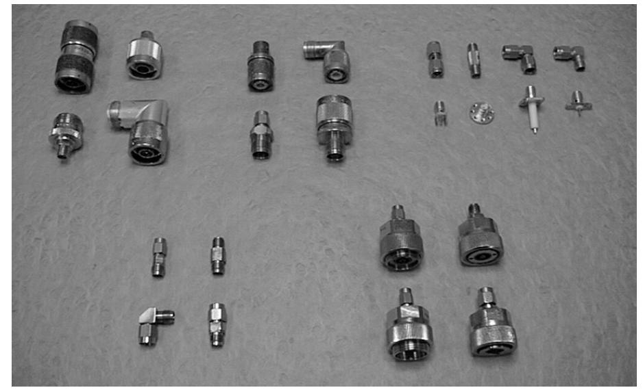
28 Coaxial Connectors
29 Coaxial Connectors Most coaxial cables and connectors in common use have a 50 characteristic impedance, with an exception being the 75 cable used in television systems. The reasoning behind these choices is that an air-filled coaxial line has minimum attenuation for a characteristic impedance of about 77 (Problem 2.27), while maximum power capacity occurs for a characteristic impedance of about 30 (Problem 3.28). A 50 characteristic impedance thus represents a compromise between minimum attenuation and maximum power capacity. Connectors are used in pairs, with a male end and a female end (or plug and jack). SMA: The need for smaller and lighter connectors led to the development of this connector in the 1960s. The outer diameter of the female end is about 0.25 in. It can be used up to frequencies in the range of GHz and is probably the most commonly used microwave connector today.
30 Homework
Photograph of the rectangular waveguide components
 Waveguides Photograph of the rectangular waveguide components BACKGROUND A transmission line can be used to guide EM energy from one point (generator) to another (load). A transmission line can support
Waveguides. Metal Waveguides. Dielectric Waveguides
 Waveguides Waveguides, like transmission lines, are structures used to guide electromagnetic waves from point to point. However, the fundamental characteristics of waveguide and transmission line waves
Waveguides GATE Problems
 Waveguides GATE Problems One Mark Questions. The interior of a 20 20 cm cm rectangular waveguide is completely 3 4 filled with a dielectric of r 4. Waves of free space wave length shorter than..can be
TOPIC 2 WAVEGUIDE AND COMPONENTS
 TOPIC 2 WAVEGUIDE AND COMPONENTS COURSE LEARNING OUTCOME (CLO) CLO1 Explain clearly the generation of microwave, the effects of microwave radiation and the propagation of electromagnetic in a waveguide
EC TRANSMISSION LINES AND WAVEGUIDES TRANSMISSION LINES AND WAVEGUIDES
 TRANSMISSION LINES AND WAVEGUIDES UNIT I - TRANSMISSION LINE THEORY 1. Define Characteristic Impedance [M/J 2006, N/D 2006] Characteristic impedance is defined as the impedance of a transmission line measured
2/18/ Transmission Lines and Waveguides 1/3. and Waveguides. Transmission Line A two conductor structure that can support a TEM wave.
 2/18/2009 3 Transmission Lines and Waveguides 1/3 Chapter 3 Transmission Lines and Waveguides First, some definitions: Transmission Line A two conductor structure that can support a TEM wave. Waveguide
EC Transmission Lines And Waveguides
 EC6503 - Transmission Lines And Waveguides UNIT I - TRANSMISSION LINE THEORY A line of cascaded T sections & Transmission lines - General Solution, Physical Significance of the Equations 1. Define Characteristic
Electromagnetic Wave Analysis of Waveguide and Shielded Microstripline 1 Srishti Singh 2 Anupma Marwaha
 Electromagnetic Wave Analysis of Waveguide and Shielded Microstripline 1 Srishti Singh 2 Anupma Marwaha M.Tech Research Scholar 1, Associate Professor 2 ECE Deptt. SLIET Longowal, Punjab-148106, India
Unit 5 Waveguides P a g e 1
 Unit 5 Waveguides P a g e Syllabus: Introduction, wave equation in Cartesian coordinates, Rectangular waveguide, TE, TM, TEM waves in rectangular guides, wave impedance, losses in wave guide, introduction
Microwave and optical systems Introduction p. 1 Characteristics of waves p. 1 The electromagnetic spectrum p. 3 History and uses of microwaves and
 Microwave and optical systems Introduction p. 1 Characteristics of waves p. 1 The electromagnetic spectrum p. 3 History and uses of microwaves and optics p. 4 Communication systems p. 6 Radar systems p.
EC6503 Transmission Lines and WaveguidesV Semester Question Bank
 UNIT I TRANSMISSION LINE THEORY A line of cascaded T sections & Transmission lines General Solution, Physicasignificance of the equations 1. Derive the two useful forms of equations for voltage and current
USE OF MICROWAVES FOR THE DETECTION OF CORROSION UNDER INSULATION
 USE OF MICROWAVES FOR THE DETECTION OF CORROSION UNDER INSULATION R. E. JONES, F. SIMONETTI, M. J. S. LOWE, IMPERIAL COLLEGE, London, UK I. P. BRADLEY, BP Exploration and Production Company, Sunbury on
RAJIV GANDHI COLLEGE OF ENGINEERING AND TECHNOLOGY Kirumampakkam,Puducherry DEPARTMENT OF ELECTRONICS AND COMMUNICATION ENGINEERING
 RAJIV GANDHI COLLEGE OF ENGINEERING AND TECHNOLOGY Kirumampakkam,Puducherry-607402 DEPARTMENT OF ELECTRONICS AND COMMUNICATION ENGINEERING QUESTION BANK FOR EC T55 - TRANSMISSION LINES AND WAVEGUIDES G.LAXMINARAYANAN,
DESIGN AND FABRICATION OF CAVITY RESONATORS
 &2@?%3 DESIGN AND FABRICATION OF CAVITY RESONATORS CHAPTER 3 DESIGN AND FABRICATION OFCAVITY RESONATORS 3.1 Introduction In the cavity perturbation techniques, generally rectangular or cylindrical waveguide
Rectangular waveguides
 Introduction Rectangular waveguides Waveguides are transmission lines commonly used in electronics, especially in higher frequency ranges like microwaves. A waveguide can be simply described as a metal
UNIT - V WAVEGUIDES. Part A (2 marks)
") Part A (2 marks) UNIT - V WAVEGUIDES 1. What is the need for guide termination? (Nov / Dec 2011) To avoid reflection loss. The termination should provide a wave impedance equal to that of the transmission
Part A (2 marks) UNIT - V WAVEGUIDES 1. What is the need for guide termination? (Nov / Dec 2011) To avoid reflection loss. The termination should provide a wave impedance equal to that of the transmission
ELEC4604. RF Electronics. Experiment 2
 ELEC4604 RF Electronics Experiment MICROWAVE MEASUREMENT TECHNIQUES 1. Introduction and Objectives In designing the RF front end of a microwave communication system it is important to appreciate that the
MICROWAVE WAVEGUIDES and COAXIAL CABLE
 MICROWAVE WAVEGUIDES and COAXIAL CABLE In general, a waveguide consists of a hollow metallic tube of arbitrary cross section uniform in extent in the direction of propagation. Common waveguide shapes are
Keysight Technologies Techniques for Advanced Cable Testing
 Keysight Technologies Techniques for Advanced Cable Testing Using FieldFox handheld analyzers Application Note Transmission lines are used to guide the flow of energy from one point to another. Line types
COAXIAL / CIRCULAR HORN ANTENNA FOR A STANDARD
 COAXIAL / CIRCULAR HORN ANTENNA FOR 802.11A STANDARD Petr Všetula Doctoral Degree Programme (1), FEEC BUT E-mail: xvsetu00@stud.feec.vutbr.cz Supervised by: Zbyněk Raida E-mail: raida@feec.vutbr.cz Abstract:
Lecture - 14 Microwave Resonator
 Basic Building Blocks of Microwave Engineering Prof Amitabha Bhattacharya Department of Electronics and Communication Engineering Indian Institute of Technology, Kharagpur Lecture - 14 Microwave Resonator
A Mode Based Model for Radio Wave Propagation in Storm Drain Pipes
 PIERS ONLINE, VOL. 4, NO. 6, 008 635 A Mode Based Model for Radio Wave Propagation in Storm Drain Pipes Ivan Howitt, Safeer Khan, and Jumanah Khan Department of Electrical and Computer Engineering The
Cut-off of Resonant Modes in Truncated Conical Cavities
 Cut-off of Resonant Modes in Truncated Conical Cavities José J. Rodal, Ph.D. June 2015 Although the fact that a truncated conical cavity displays an absence of sharp cut-off frequencies has been remarked
INTRODUCTION OF WAVEGUIDES
 INTRODUCTION OF WAVEGUIDES Under guidance of Joydeep Sengupta sir VNIT BT14ECE031 CHARAN SAI KATAKAM 1 INTRODUCTION TO WAVEGUIDES In a waveguide energy is transmitted in the form of electromagnetic waves
Projects in microwave theory 2009
 Electrical and information technology Projects in microwave theory 2009 Write a short report on the project that includes a short abstract, an introduction, a theory section, a section on the results and
Times Microwave Systems Hermetically Sealed Assemblies
 SCOPE This Specification details the Electrical, Mechanical and Environmental Characteristics of Times Microwave Systems MILTECH 480.48 Diameter Hermetically Sealed Coaxial Transmission Lines. This product
Ka-BAND KLOPFENSTEIN TAPERED IMPEDANCE TRANSFORMER FOR RADAR APPLICATIONS
 Progress In Electromagnetics Research C, Vol. 27, 253 263, 2012 Ka-BAND KLOPFENSTEIN TAPERED IMPEDANCE TRANSFORMER FOR RADAR APPLICATIONS L. Resley and H. Song * Department of Electrical and Computer Engineering,
RP SMA Male Right Angle Connector Solder Attachment for PE-SR402AL, PE-SR402FL, RG402
 RP SMA Male Right Angle Connector Solder Attachment for PE-SR402AL, PE-SR402FL, RG402 RF Connectors Technical Data Sheet PE4790 Configuration SMA Male Reverse Polarity Connector MIL-STD-348 50 Ohms Right
Critical Study of Open-ended Coaxial Sensor by Finite Element Method (FEM)
") International Journal of Applied Science and Engineering 3., 4: 343-36 Critical Study of Open-ended Coaxial Sensor by Finite Element Method (FEM) M. A. Jusoha*, Z. Abbasb, M. A. A. Rahmanb, C. E. Mengc,
International Journal of Applied Science and Engineering 3., 4: 343-36 Critical Study of Open-ended Coaxial Sensor by Finite Element Method (FEM) M. A. Jusoha*, Z. Abbasb, M. A. A. Rahmanb, C. E. Mengc,
 VALLIAMMAI ENGINEERING COLLEGE SRM Nagar, Kattankulathur-603 203 DEPARTMENT OF ELECTRONICS AND COMMUNICATION ENGINEERING EC6503 TRANSMISSION LINES AND WAVEGUIDES YEAR / SEMESTER: III / V ACADEMIC YEAR:
Electromagnetics, Microwave Circuit and Antenna Design for Communications Engineering
 Electromagnetics, Microwave Circuit and Antenna Design for Communications Engineering Second Edition Peter Russer ARTECH HOUSE BOSTON LONDON artechhouse.com Contents Preface xvii Chapter 1 Introduction
Monoconical RF Antenna
 Page 1 of 8 RF and Microwave Models : Monoconical RF Antenna Monoconical RF Antenna Introduction Conical antennas are useful for many applications due to their broadband characteristics and relative simplicity.
High Power Over-Mode 90 Bent Waveguides for Circular TM 01 and Coaxial TEM Mode Transmission
 Progress In Electromagnetics Research M, Vol. 60, 189 196, 2017 High Power Over-Mode 90 Bent Waveguides for Circular TM 01 and Coaxial TEM Mode Transmission Xiaomeng Li, Xiangqiang Li *, Qingxiang Liu,
We are IntechOpen, the world s leading publisher of Open Access books Built by scientists, for scientists. International authors and editors
 We are IntechOpen, the world s leading publisher of Open Access books Built by scientists, for scientists 3,900 116,000 120M Open access books available International authors and editors Downloads Our
ECSE 352: Electromagnetic Waves
 December 2008 Final Examination ECSE 352: Electromagnetic Waves 09:00 12:00, December 15, 2008 Examiner: Zetian Mi Associate Examiner: Andrew Kirk Student Name: McGill ID: Instructions: This is a CLOSED
PAPER Wide-Band Coaxial-to-Coplanar Transition
 2030 PAPER Wide-Band Coaxial-to-Coplanar Transition Toshihisa KAMEI a),yozoutsumi, Members, NguyenQUOCDINH, and Nguyen THANH, Student Members SUMMARY Targeting the transition from a coaxial wave guide
SA26B-10 DATA SHEET. 10 db Fixed Attenuator SMA Male To SMA Female Up To 26 GHz Rated To 2 Watts With Passivated Stainless Steel Body.
 10 db Fixed Attenuator SMA Male To SMA Female Up To 26 GHz Rated To 2 Watts With Passivated Stainless Steel Body Fairview Microwave carries a broad selection of fixed attenuators with a wide range of attenuation
Cable Attachment Method (Shield/Contact) Size Length, in [mm] 0.98 [24.89] Width/Dia., in [mm] [9.53]. Weight, lbs [g] 0.02 [9.07] 3.
![Cable Attachment Method (Shield/Contact) Size Length, in [mm] 0.98 [24.89] Width/Dia., in [mm] [9.53]. Weight, lbs [g] 0.02 [9.07] 3.](/thumbs/94/121044667.jpg "Cable Attachment Method (Shield/Contact) Size Length, in [mm] 0.98 [24.89] Width/Dia., in [mm] [9.53]. Weight, lbs [g] 0.02 [9.07] 3.") Configuration Interface Type Cable Attachment Method (Shield/Contact) Body Style PE-SR402AL,PE-SR402FL,RG402 Clamp/Solder Straight Electrical Specifications Impedance, Ohms 50 Mechanical Specifications
Configuration Interface Type Cable Attachment Method (Shield/Contact) Body Style PE-SR402AL,PE-SR402FL,RG402 Clamp/Solder Straight Electrical Specifications Impedance, Ohms 50 Mechanical Specifications
Waveguide Calibration with Copper Mountain Technologies VNA
 Clarke & Severn Electronics Ph: +612 9482 1944 BUY NOW www.cseonline.com.au Introduction Waveguide components possess certain advantages over their counterpart devices with co-axial connectors: they can
Lab Manual Experiment No. 2
 Lab Manual Experiment No. 2 Aim of Experiment: Observe the transient phenomenon of terminated coaxial transmission lines in order to study their time domain behavior. Requirement: You have to install a
INVESTIGATION OF THE LONGITUDINAL FIELD COMPONENT INSIDE THE GTEM 1750
 INVESTIGATION OF THE LONGITUDINAL FIELD COMPONENT INSIDE THE GTEM 1750 H.M. LOOE, Y. HUANG B.G. LOADER, M.J. ALEXANDER, W. LIANG The University of Liverpool, UK Introduction GTEM (Gigahertz Traverse Electromagnetic)
04th - 16th August, th International Nathiagali Summer College 1 CAVITY BASICS. C. Serpico
 39th International Nathiagali Summer College 1 CAVITY BASICS C. Serpico 39th International Nathiagali Summer College 2 Outline Maxwell equations Guided propagation Rectangular waveguide Circular waveguide
MULTIFLEX The flexible alternative to SEMI-RIGID
 MULTIFLEX The flexible alternative to SEMI-RIGID Content Product description................................................................. 65 Features and benefits...............................................................
EC 200 CHARACTERISTICS D A T A S H E E T. Kabelwerk EUPEN AG cable. M e c h a n i c a l c h a r a c t e r i s t i c s
 EC 200 EC200 - Rev. 3-23.06.11 Characteristic impedance 50 ± 2 Material copper wire Nominal capacity (pf/m) 80.5 Construction - Relative propagation velocity (%) 83 Diameter (mm) 1.05 Inductance (µh/m)
R.K.YADAV. 2. Explain with suitable sketch the operation of two-cavity Klystron amplifier. explain the concept of velocity and current modulations.
 Question Bank DEPARTMENT OF ELECTRONICS AND COMMUNICATION SUBJECT- MICROWAVE ENGINEERING(EEC-603) Unit-III 1. What are the high frequency limitations of conventional tubes? Explain clearly. 2. Explain
Low Loss Pre-Connectorized Cable Sets, LL58 Series, DC-3.5GHz
 Low Loss Pre-Connectorized Cable Sets, LL58 Series, DC-3.5 reliable performance, dependable service Replace traditional RG types for benefit of: lower loss better shielding > - 90dB Drop in replacement
Localization and Identifying EMC interference Sources of a Microwave Transmission Module
 Localization and Identifying EMC interference Sources of a Microwave Transmission Module Ph. Descamps 1, G. Ngamani-Njomkoue 2, D. Pasquet 1, C. Tolant 2, D. Lesénéchal 1 and P. Eudeline 2 1 LaMIPS, Laboratoire
SERIESN50, COAXIAL CONNECTORS
 SERIESN50, COAXIAL CONNECTORS DESCRIPTION CONTENTS PAGE HUBER+SUHNER N connectors are available with 50 and 75 impedance. The frequency range extends to 18 GHz, depending on the connector and cable type.
Test Cable Assemblies
 Test Cable Assemblies DC-65 GHz 8851 SW Old Kansas Ave. Stuart, FL 34997 USA +1-772-286-9300 +1-800-544-5594 sales@emc-rflabs.com www.emc-rflabs.com Premium Test Cable Lab-Flex 200 Frequency to 31 GHz
Ultra High Frequency Measurements
 Ultra High Frequency Measurements Desmond Fraser desmond@rheintech.com 703.689.0368 360 Herndon Parkway Suite 1400 Herndon, VA 20170 IEEE EMC DC / N. VA Chapter 31 January 2012 Overview We ll review Millimeter
SMA Male Connector Crimp/Solder Attachment for RG174, RG316, RG188 Gold Plated
 SMA Male Connector Crimp/Solder Attachment for RG174, RG316, RG188 Gold Plated RF Connectors Technical Data Sheet PE45145 Configuration SMA Male Connector 50 Ohms Straight Body Geometry RG174, RG316, RG188
1. Evolution Of Fiber Optic Systems
 OPTICAL FIBER COMMUNICATION UNIT-I : OPTICAL FIBERS STRUCTURE: 1. Evolution Of Fiber Optic Systems The operating range of optical fiber system term and the characteristics of the four key components of
(i) Determine the admittance parameters of the network of Fig 1 (f) and draw its - equivalent circuit.
 Determine the admittance parameters of the network of Fig 1 (f) and draw its - equivalent circuit.") I.E.S-(Conv.)-1995 ELECTRONICS AND TELECOMMUNICATION ENGINEERING PAPER - I Some useful data: Electron charge: 1.6 10 19 Coulomb Free space permeability: 4 10 7 H/m Free space permittivity: 8.85 pf/m Velocity
I.E.S-(Conv.)-1995 ELECTRONICS AND TELECOMMUNICATION ENGINEERING PAPER - I Some useful data: Electron charge: 1.6 10 19 Coulomb Free space permeability: 4 10 7 H/m Free space permittivity: 8.85 pf/m Velocity
Test Cable Assemblies W2 Series - Low Loss & Phase Stability cable W1 Series - Ultra Low Loss cable W-Test Series - for Precition Test
 MICROWAVE FARMʼs Test Cable assemblies are complete line of high performance flexible microwave cable assemblies. The W2/W1 seies have Low density PTFE(W201, W213 and W1 series) and porus PFA (W202, W203)
Fundamental Mode RF Power Dissipated in a Waveguide Attached to an Accelerating Cavity. Y. W. Kang
 ANL/ASD/RP 793 96 DE93 011758 Fundamental Mode RF Power Dissipated in a Waveguide Attached to an Accelerating Cavity Y. W. Kang RF Group Accelerator Systems Division Argonne National Laboratory February
電子回路論第 7 回 Electric Circuits for Physicists #7
 電子回路論第 7 回 Electric Circuits for Physicists #7 東京大学理学部 理学系研究科物性研究所勝本信吾 Shingo Katsumoto Outline 4.5 Field Effect Transistors (FETs) Ch.5 Distributed constant circuits 5.1 Transmission lines 5.1.1 Coaxial
Dielectric Circular Waveguide Loaded with Dielectric Material
 Dielectric Circular Waveguide Loaded with Dielectric Material Dimple N. Agrawal 1, Raj Hakani 2 PG Student, Dept. of Electronics and Communication, Silver Oak College of Engineering and Technology, Ahmedabad,
Evanescent-Mode Filters with Arbitrarily Positioned Ridges in Circular Waveguide
 Evanescent-Mode Filters with Arbitrarily Positioned Ridges in Circular Waveguide Seng Yong Yu and Jens Bornemann Department of Electrical and Computer Engineering, University of Victoria, BC, Canada syyu@ece.uvic.ca
A New TEM Horn Antenna Designing Based on Plexiglass Antenna Cap
 Journal of Applied Science and Engineering, Vol. 21, No. 3, pp. 413 418 (2018) DOI: 10.6180/jase.201809_21(3).0012 A New TEM Horn Antenna Designing Based on Plexiglass Antenna Cap Lin Teng and Jie Liu*
Cray Valley Radio Society. Real Life Wire Antennas
 Cray Valley Radio Society Real Life Wire Antennas 1 The basic dipole The size of an antenna is determined by the wavelength of operation In free space: ~3x10 8 m/s Frequency x Wavelength = Speed of Light,
Labs. Introduction. Specialty Family
 INC. Labs Introduction Specialty Family Features K-Jumper: Affordable, High Performance Interconnect up to 35 GHz Space-Flex : Semi-Rigid and Flexible Cable Assemblies for S-Level Space T-Flex : Flexible
Microwave Cancer Therapy
 Page 1 of 9 RF and Microwave Models : Microwave Cancer Therapy Microwave Cancer Therapy Electromagnetic heating appears in a wide range of engineering problems and is ideally suited for modeling in COMSOL
Design of a prime-focus feed with backward radiation
 Design of a prime-focus feed with backward radiation Libor SLÁMA 1, Rastislav GALUŠČÁK - OM6AA 1, Pavel HAZDRA 1 1 Dept. of Electromagnetic Field, Czech Technical University, Technická 2, 166 27 Praha,
SMA Male QD Connector Crimp/Solder Attachment For RG142, RG223, RG400, RG55
 SMA Male QD Connector Crimp/Solder Attachment For RG142, RG223, RG400, RG55 RF Connectors Technical Data Sheet Configuration SMA Male Connector 50 Ohms Straight Body Geometry RG142, RG223, RG400, RG55
Projects in microwave theory 2017
 Electrical and information technology Projects in microwave theory 2017 Write a short report on the project that includes a short abstract, an introduction, a theory section, a section on the results and
International Journal of Advanced Engineering Technology E-ISSN
 Research Article ANALYTICAL STUDY OF HELICALLY CLADDED OPTICAL WAVEGUIDE WITH DIFFERENT PITCH ANGLES Mishra V.* Gautam A. K. Taunk B. R. Address for Correspondence Sr. Member IEEE, Electronics Engineering
ELECTROMAGNETIC COMPATIBILITY HANDBOOK 1. Chapter 8: Cable Modeling
 ELECTROMAGNETIC COMPATIBILITY HANDBOOK 1 Chapter 8: Cable Modeling Related to the topic in section 8.14, sometimes when an RF transmitter is connected to an unbalanced antenna fed against earth ground
Fiber Optic Communication Systems. Unit-04: Theory of Light. https://sites.google.com/a/faculty.muet.edu.pk/abdullatif
 Unit-04: Theory of Light https://sites.google.com/a/faculty.muet.edu.pk/abdullatif Department of Telecommunication, MUET UET Jamshoro 1 Limitations of Ray theory Ray theory describes only the direction
Research Article Simulation Study of the Relationship between Partial Discharge and Ultrahigh-Frequency Electromagnetic Wave in GIS
 Research Journal of Applied Sciences, Engineering and Technology 7(9): 1744-1749, 014 DOI:10.1906/rjaset.7.458 ISSN: 040-7459; e-issn: 040-7467 014 Maxwell Scientific Publication Corp. Submitted: March
Number of Sections. Contact factory for specific requirements not listed above.
 Tubular Filters MHz to 20 GHz Chebyshev Response Standard 4 Convenient Sizes Reliable Sturdy Construction Lorch Microwave tubular filters are available in bandpass and lowpass configurations. A low ripple
THE circular rectangular (C-R) coaxial waveguide has
 coaxial waveguide has") 414 IEEE TRANSACTIONS ON MICROWAVE THEORY AND TECHNIQUES, VOL. 45, NO. 3, MARCH 1997 The Higher Order Modal Characteristics of Circular Rectangular Coaxial Waveguides Haiyin Wang, Ke-Li Wu, Senior Member,
414 IEEE TRANSACTIONS ON MICROWAVE THEORY AND TECHNIQUES, VOL. 45, NO. 3, MARCH 1997 The Higher Order Modal Characteristics of Circular Rectangular Coaxial Waveguides Haiyin Wang, Ke-Li Wu, Senior Member,
PERFORMANCE STUDIES OF RADIAL LINE SLOT ARRAY (RLSA) ANTENNA AT 5.8 GHz ON DIFFERENT MATERIALS Omar Abdul Aziz Tharek Abdul Rahman
 ANTENNA AT 5.8 GHz ON DIFFERENT MATERIALS Omar Abdul Aziz Tharek Abdul Rahman") 102 Recent Developments in Small Size Antenna 9 PERFORMANCE STUDIES OF RADIAL LINE SLOT ARRAY (RLSA) ANTENNA AT 5.8 GHz ON DIFFERENT MATERIALS Omar Abdul Aziz Tharek Abdul Rahman 9.1 INTRODUCTION The type
102 Recent Developments in Small Size Antenna 9 PERFORMANCE STUDIES OF RADIAL LINE SLOT ARRAY (RLSA) ANTENNA AT 5.8 GHz ON DIFFERENT MATERIALS Omar Abdul Aziz Tharek Abdul Rahman 9.1 INTRODUCTION The type
TERM PAPER OF ELECTROMAGNETIC
 TERM PAPER OF ELECTROMAGNETIC COMMUNICATION SYSTEMS TOPIC: LOSSES IN TRANSMISSION LINES ABSTRACT: - The transmission lines are considered to be impedance matching circuits designed to deliver rf power
Conceptual Design Of An Ideal Variable Coupler For Superconducting Radiofrequency 1.3GHz Cavities. Chen Xu, Sami Tantawi
 Conceptual Design Of An Ideal Variable Coupler For Superconducting Radiofrequency 1.3GHz Cavities. Chen Xu, Sami Tantawi Stanford Linear Accelerator Center, Stanford University, 2575 Sand Hill Road, Menlo
Microwave Cable Products
 Microwave Cable Products MaxGain Features & Benefits: Lowest Insertion Loss Available, DC-50 GHz Ultra Stable Insertion Loss, Phase and VSWR with Flexing Flex Durability Very Good Excellent Phase Tracking
Microwave Coax Cable
 Cable LINCOS microwave coaxial cable basic construction is shown below : Ø 1. Inner Conductor : Solid or Strand Sliver Plated Copper Ø 2. Insulation : Wrapped Low Density PTFE Ø 3. Outer Conductor : Sliver
Microwave Engineering
 Microwave Circuits 1 Microwave Engineering 1. Microwave: 300MHz ~ 300 GHz, 1 m ~ 1mm. a. Not only apply in this frequency range. The real issue is wavelength. Historically, as early as WWII, this is the
Lecturer Note. Lecturer-10
 Lecturer Note Sub: MWE Subject code: PCEC 4402 Sem: 8 th Prepared by: Mr. M. R. Jena Lecturer-10 Components in a signal flow graph Nodes: each port, i, of a microwave network has two nodes, a, and b. Node
A Low-Loss VHF/UHF Diplexer
 A Low-Loss / Diplexer Why use two lengths of expensive feed line when one will do? This hy box lets you use one feed line for both energy, simultaneously! By Pavel Zanek, OK1DNZ Do you need to operate
RF Connectors Technical Data Sheet. Gold over Nickel Plated Beryllium Copper Contact. Size in [11.81 mm] . Weight lbs [3.18 g].
![RF Connectors Technical Data Sheet. Gold over Nickel Plated Beryllium Copper Contact. Size in [11.81 mm] . Weight lbs [3.18 g].](/thumbs/90/101629325.jpg "RF Connectors Technical Data Sheet. Gold over Nickel Plated Beryllium Copper Contact. Size in [11.81 mm] . Weight lbs [3.18 g].") RP SMA Male Connector Solder Attachment for PE-SR402AL, PE-SR402FL, PE-SR402FLJ, PE- SR402TN, RG402, Gold Plated Brass Body RF Connectors Technical Data Sheet PE44724 Configuration SMA Male Reverse Polarity
RP SMA Male Connector Solder Attachment for PE-SR402AL, PE-SR402FL, PE-SR402FLJ, PE- SR402TN, RG402, Gold Plated Brass Body RF Connectors Technical Data Sheet PE44724 Configuration SMA Male Reverse Polarity
Optimizing Microwave Signal Transmissions In Extreme Cryogenic Environments Times Microwave Systems SiO2 Products
 Optimizing Microwave Signal Transmissions In Extreme Cryogenic Environments Times Microwave Systems Products Martin Winkler Product Manager Times Microwave Systems 358 Hall Avenue Wallingford, CT 06492
Tru products are now under the Tru-Win brand from Winchester Interconnect.
 TRU MEIA Series Tru-Win MEIA offers the latest innovation in high power connector design. The MEIA interface provides equivalent kw power handling compared to similar EIA connector line sizes but provides
High Frequency. ECT-CPG com shop ECT-CPG com
 High Frequency HiGH FreQuenCY High Frequency or Radio Frequency (RF) coaxial probes are used for testing high speed circuits in a variety of industries including automotive, wireless communications, satellite,
SMB Connectors. Adaptors-50Ω. Plug to Plug. Jack to Jack. Plug to Jack. Bulkhead Jack to Jack
 SMB Connectors Adaptors-50Ω Plug to Plug 1P-801-00 Jack to Jack 1P-802-00 Plug to Jack 1P-803-00 Bulkhead Jack to Jack 1P-804-18 Mini-SMB 75Ω Straight Plug 1P75-111-00 Cable group RG316 Straight PCB Jack
L-BAND COPLANAR SLOT LOOP ANTENNA FOR INET APPLICATIONS
 L-BAND COPLANAR SLOT LOOP ANTENNA FOR INET APPLICATIONS Jeyasingh Nithianandam Electrical and Computer Engineering Department Morgan State University, 500 Perring Parkway, Baltimore, Maryland 5 ABSTRACT
Exercise problems of topic 1: Transmission line theory and typical waveguides
 Exercise problems of topic 1: Transmission line theory and typical waveguides Return your answers in the contact sessions on a paper; either handwritten or typescripted. You can return them one by one.
SRI VENKATESWARA COLLEGE OF ENGINEERING DEPARTMENT OF ELECTRONICS AND COMMUNICATION ENGINEERING Date : UNIVERSITY QUESTIONS AND ANSWERS
 SRI VENKATESWARA COLLEGE OF ENGINEERING DEPARTMENT OF ELECTRONICS AND COMMUNICATION ENGINEERING Date : 02.07.2015 UNIVERSITY QUESTIONS AND ANSWERS Subject : Transmission lines & Wave Guides Sub Code :
SPS Enamelled flanges Simulations & Measurements. Fritz Caspers and Jose E. Varela
 SPS Enamelled flanges Simulations & Measurements Fritz Caspers and Jose E. Varela Outline Introduction Simulations Measurements Conclusions Outline Introduction Simulations Measurements Conclusions Introduction
Amphenol RF MCX. MCX Connectors MCX. Description. Features/Benefits. Applications
 Amphenol RF 20 Connectors Description connectors conform to the European CECC 22000 spec and were introduced in the 1980 s. While the uses identical inner contact and insulator dimensions as the SMB, the
A Pin-Loaded Microstrip Patch Antenna with the Ability to Suppress Surface Wave Excitation
 Progress In Electromagnetics Research C, Vol. 62, 131 137, 2016 A Pin-Loaded Microstrip Patch Antenna with the Ability to Suppress Surface Wave Excitation Ayed R. AlAjmi and Mohammad A. Saed * Abstract
Physical Test Setup for Impulse Noise Testing
 Physical Test Setup for Impulse Noise Testing Larry Cohen Overview Purpose: Use measurement results for the EM coupling (Campbell) clamp to determine a stable physical test setup for impulse noise testing.
Practical Antennas and. Tuesday, March 4, 14
 Practical Antennas and Transmission Lines Goals Antennas are the interface between guided waves (from a cable) and unguided waves (in space). To understand the various properties of antennas, so as to
Cu 0.37 Brass Cu 0.37 Brass
 To: From: EDGES MEMO #148 MASSACHUSETTS INSTITUTE OF TECHNOLOGY HAYSTACK OBSERVATORY WESTFORD, MASSACHUSETTS 01886 October 7, 2014 Telephone: 781-981-5400 Fax: 781-981-0590 EDGES Group Alan E.E. Rogers
Dual-band Antenna Feed Solution for 5G. A dual-band coaxial- and waveguide fed antenna feed for reflector LUKAS MARED
 Dual-band Antenna Feed Solution for 5G A dual-band coaxial- and waveguide fed antenna feed for reflector antenna systems Master s thesis in Wireless, photonics and space engineering LUKAS MARED Department
SMB Plug Connector Crimp/Solder Attachment for RG174, RG316, RG188, LMR-100, PE-B100, PE-C100, inch
 SMB Plug Connector Crimp/Solder Attachment for RG174, RG316, RG188, LMR-100, PE-B100, PE-C100, 0100 inch RF Connectors Technical Data Sheet PE4046 Configuration SMB Plug Connector MIL-STD-348A 50 Ohms
AM BASIC ELECTRONICS TRANSMISSION LINES JANUARY 2012 DEPARTMENT OF THE ARMY MILITARY AUXILIARY RADIO SYSTEM FORT HUACHUCA ARIZONA
 AM 5-306 BASIC ELECTRONICS TRANSMISSION LINES JANUARY 2012 DISTRIBUTION RESTRICTION: Approved for Pubic Release. Distribution is unlimited. DEPARTMENT OF THE ARMY MILITARY AUXILIARY RADIO SYSTEM FORT HUACHUCA
Enhancement of Directional Characteristics of Sectional Cylindrical Slotted Waveguide Antennas
 Abstract AMSE JOURNALS 2015-Series: Modelling A; Vol. 88; N 1; pp 41-52 Submitted Feb. 2015; Revised March. 23, 2015; Accepted April 15, 2015 Enhancement of Directional Characteristics of Sectional Cylindrical
with a Suspended Stripline Feeding
 Wide Band and High Gain Planar Array with a Suspended Stripline Feeding Network N. Daviduvitz, U. Zohar and R. Shavit Dept. of Electrical and Computer Engineering Ben Gurion University i of the Negev,
UHV Double-Ended SMA Feedthrough, , Conflat compatible flange
 SMA Interface SMA Interface Grounded and Feedthroughs UHV Double-Ended SMA Feedthrough, 110730, Conflat compatible flange UHV male SMA cable 5 assembly, 110755, Kapton insulated 50-ohm coaxial cable Features
ACompactN-Way Wilkinson Power Divider Using a Novel Coaxial Cable Implementation for VHF Band
 Progress In Electromagnetics Research Letters, Vol. 62, 49 55, 2016 ACompactN-Way Wilkinson Power Divider Using a Novel Coaxial Cable Implementation for VHF Band S. S. Kakatkar *,PrafullIrpache,andK.P.Ray