Physical Test Setup for Impulse Noise Testing
|
|
|
- Dustin Anderson
- 6 years ago
- Views:
Transcription

1 Physical Test Setup for Impulse Noise Testing Larry Cohen
2 Overview Purpose: Use measurement results for the EM coupling (Campbell) clamp to determine a stable physical test setup for impulse noise testing. Define a test setup diagram for the standard that will allow use of the clamp up to 1000 MHz (allows additional use for radiated immunity testing) Overview of EM coupling (Campbell) clamp Test setups for EM clamp impulse noise testing and characterization of the EM clamp Presentation of measurement data for various clamp configurations Observations for stable clamp operation Next steps and discussion points 6/17/2015 2
3 Overview of the EM Coupling (Campbell) Clamp EM coupling (Campbell) clamp specification defined in Annex 40B of Originally designed for common-mode interference signal injection up to 250 MHz into 1000Base-T channel Works as a coaxial transformer External ferrite suppression clamp network is required at far-end port for isolation of link partner and to suppress reflections at a (common-mode) impedance discontinuity Nylon Screws BNC Connector (9 mm back from edge) Keying Bolt Clamping Screws Keying Bolt 300 mm Dielectric Outer Conductor Inner Conductor 6/17/2015 3
4 Properties of the EM Coupling (Campbell) Clamp Advantages Produces effects similar to real-world interference; injects identical commonmode signal on all four pairs similar to exposure to an external EM field Differential disturber signal created by channel imbalance; differential disturbers are NOT identical as would be the case in a real channel Non-intrusive, does not disturb channel or degrade channel insertion loss and return loss Coupling characteristics fairly consistent between units because of specified construction; coupling characteristics of EM absorbing clamps differ significantly between different manufacturers Disadvantages Produced by only one supplier (ETS) Requires relatively high power input stimulus because of large coupling losses Internal resonance (reflections from internal impedance discontinuities) place test configuration restrictions for test signal frequencies above 250 MHz External ferrite suppression clamp network must provide a minimum commonmode attenuation over a wide bandwidth 6/17/2015 4
5 Example EM Clamp Setup for Impulse Noise (and Radiated Immunity) Testing Arbitrary Waveform Generator Generates modulated RF carrier signal (80 MHz to 1000 MHz) or commonmode impulse noise waveforms RF Out 50 EM clamp injects an identical common-mode interference signal into all four pairs of the test link to simulate impulse noise events and/or radiated interference ingress. 50 Power Amplifier (>20 db Gain) Cat 5e/6 UTP patch cord used in test channel (>2m) The cable above the ground plane forms a common-mode transmission line. Z CHAR is determined by height above the ground plane (about 1 inch for this setup) Optional (low-frequency) ferrite clamp Term Wideband ferrite clamp network Long cable segment may be 6-around-1 cable configuration to allow injection of alien crosstalk meter Cat 5e/6 segment EM Coupling Clamp (ETS CC-101) 2.5G/5G PHY Under Test RJ45 Port under test Ferrite clamp network provides both isolation to link partner and elimination of common-mode reflections which cause deep common-mode coupling nulls. 75 L1 L1 = 10 to 15 cm 61 Metal ground plate L2 L2 = 0 to 4 cm RJ45 RJ45 Patch panel 2.5G/5G Far-End RJ45 Link Partner 6/17/2015 Cat 5e/6 UTP patch cord used in test channel (2-3m) 5
6 Test Setup to Measure EM (Campbell) Clamp Coupling Network analyzer measures common-mode and differential-mode coupling from the coupling clamp into one of four pairs. Agilent E5071A 4-Port Network Analyzer Port 1 50 Port 2 50 Port 3 50 Logical differential port allows network analyzer to compute both differential-mode and common-mode coupling in a single (per pair) measurement. Port 4 50 Logical Port #2 (Single-ended 50 ) Logical Port #1 (Single-ended 50 ) Cable above ground plane forms a common-mode transmission line. Z0 determined by height above plane. Logical Port #3 (Differential 100 ) RJ45-to-SMA Breakout and Termination RJ45 Box Cat 5e/6 UTP patch cord used in test channel (>2m) Optional (low-frequency) ferrite clamp Ferrite clamps EM Coupling Clamp (ETS CC-101) 75 L1 L1 = 10 to 15 cm 61 Metal ground plate Ohm DM RJ Ohm CM Termination L2 L2 = 0 to 4 cm All unused pairs on the RJ45 Breakout and Termination Box are terminated with 50 Ohms. The RJ45 connector and enclosure are fully shielded, and the enclosure is bonded to the metal ground plate. 6/17/2015 L3 L3 >= 2 meters 6
7 Test Setup to Measure EM (Campbell) Clamp Coupling 6/17/2015 7
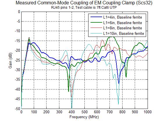
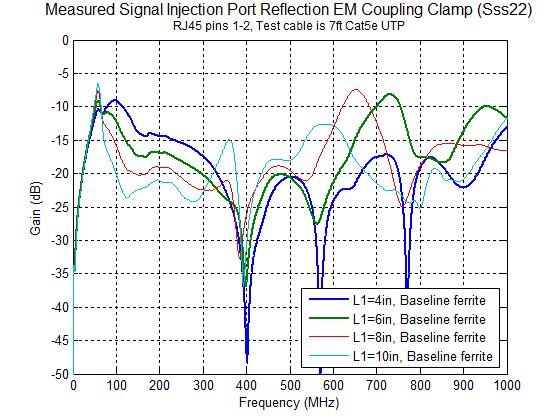
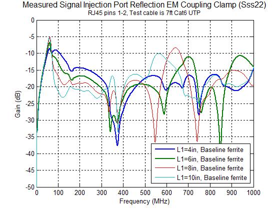
8 EM Coupling (Campbell) Clamp Measurement Results Parameters measured Common-mode coupling to test cable Differential-mode coupling to test cable Reflection at clamp input signal port Test cables 7 ft Cat 5e patch cord with 100 Ohm differential/50 Ohm common-mode termination 7 ft Cat 6 patch cord with 100 Ohm differential/50 Ohm common-mode termination Test configurations Variation of distance between RJ45 port and clamp (L1) from 2 inches to 14 inches in 2 inch steps; plots only show results from L1 = 4, 6, 8, 10 inches Measurement of configuration with L1=6 inches with various ferrite configurations Definitions Baseline ferrite: Wideband ferrite clamp network at link partner port of clamp consisting three snap-on cable clamps of Fair-Rite material #61, #31, and #75 Standalone clamp: No snap-on ferrite clamps installed (demonstrates need for ferrite clamps) Note material #61 is for high frequencies (above 100 MHz), material #75 is for low frequencies (below 20 MHz), and material #31 is for range from 10 MHz to 200 MHz 6/17/2015 8
9 9
10 10
11 11
12 12

13 13
14 14
15 15
16 16
17 17
18 Observations from EM Coupling Clamp Measurements Define usable bandwidth as a region where the common-mode coupling transfer function is reasonably flat and does not have any deep nulls The wideband ferrite clamp network at the link partner (far-end) port of the clamp is MANDATORY for all usable test configuration to provide isolation for auxiliary equipment and eliminate coupling nulls from common-mode reflections For usable bandwidth to 350 MHz with Cat 5e UTP and Cat 6 UTP, L1 (distance between clamp and DUT) can widely vary from 10 cm to 30 cm (4 inches to 12 inches) For usable bandwidth beyond 350 MHz up to 1GHz with Cat 5e UTP and Cat 6 UTP, L1 (distance between clamp and DUT) should be between 10 cm and 15 cm (4 and 6 inches), possibly less than 15 cm (6 inches) maximum for Cat 6 UTP The addition of 0.25 inch thick small metal slabs between the clamp and DUT (RJ45 test port) to reduce the height of the test cable above the ground plane (reduce common-mode impedance) slightly improved Added low-frequency ferrite clamp (material #75) improves clamp input port return loss and flattens common-mode coupling curve, but reduces low frequency commonmode coupling The low frequency common-mode coupling loss is very high; this may be problem for EFT waveform impulse noise testing The test setup diagram shown in slide #5 may be useful as a starting point in defining a test setup for impulse noise testing in the standard 6/17/
19 Next Steps and Discussion Points Measure impedance of ferrite clamp network to provide a proper standard specification Test clamp coupling with screened and shielded cable Should an RJ45 junction be added 2 to 3 meters from the DUT port on the test cable configuration? Realistic installation practice; simulates patch cord run from desk/wall RJ45 jack to network equipment Increases common-mode to differential conversion Should we consider alternative test setups with either an EM absorbing clamp or a differential injection test fixture? 6/17/
Methods for Testing Impulse Noise Tolerance
 Methods for Testing Impulse Noise Tolerance May,6,2015 Larry Cohen Overview Purpose: Describe some potential test methods for impulse noise tolerance What we will cover in this presentation: Discuss need
EFFECT OF SHIELDING ON CABLE RF INGRESS MEASUREMENTS LARRY COHEN
 EFFECT OF SHIELDING ON CABLE RF INGRESS MEASUREMENTS LARRY COHEN OVERVIEW Purpose: Examine the common-mode and differential RF ingress levels of 4-pair UTP, F/UTP, and F/FTP cables at an (RJ45) MDI port
Impulse Noise Measurement Test Setup
 Impulse Noise Measurement Test Setup 1/27/2015 Ramin Shirani Larry Cohen Impulse Noise Problem Overview Problem: Impulse noise events in the enterprise environment may degrade the operational BER of otherwise
A Proposed Specification for RFI Ingress Limit in 802.3ch Automotive Links. Ramin Farjadrad Larry Cohen Aquantia Corp.
 A Proposed Specification for RFI Ingress Limit in 802.3ch Automotive Links Ramin Farjadrad Larry Cohen Aquantia Corp. Narrowband RF Interference RF Interference Coupling to Differential Pairs ALSE 80MHz
MEASUREMENTS OF COUPLING THROUGH BRAIDED SHIELD VIA NEW CONDUCTED IMMUNITY TECH- NIQUE
 Progress In Electromagnetics Research C, Vol. 11, 61 68, 2009 MEASUREMENTS OF COUPLING THROUGH BRAIDED SHIELD VIA NEW CONDUCTED IMMUNITY TECH- NIQUE M. Ghassempouri College of Electrical Engineering Iran
FISCHER CUSTOM COMMUNICATIONS, INC.
 FISCHER CUSTOM COMMUNICATIONS, INC. Current Probe Catalog FISCHER CUSTOM COMMUNICATIONS, INC. Fischer Custom Communications, Inc., is a manufacturer of custom electric and magnetic field sensors for military
Cabling Ad Hoc Cat 5e Measurements
 Cabling Ad Hoc Cat 5e Measurements Larry Cohen Solarflare Communications 1 Overview Cabling Ad Hoc Test Plan Measurement One Cat 5e horizontal cable sample, four test channel configurations characterized
Antenna Matching Within an Enclosure Part II: Practical Techniques and Guidelines
 Antenna Matching Within an Enclosure Part II: Practical Techniques and Guidelines By Johnny Lienau, RF Engineer June 2012 Antenna selection and placement can be a difficult task, and the challenges of
Chapter 12: Transmission Lines. EET-223: RF Communication Circuits Walter Lara
 Chapter 12: Transmission Lines EET-223: RF Communication Circuits Walter Lara Introduction A transmission line can be defined as the conductive connections between system elements that carry signal power.
Coupling- / Decoupling Network. 150 khz 300 MHz. 150 khz 230 MHz. 10 khz 230 MHz. IEC and CISPR 15 / CISPR 22 IEC
 Coupling- / Decoupling Network 150 khz 300 MHz IEC 61000-4 - 6 and CISPR 15 / CISPR 22 150 khz 230 MHz IEC 61000-4 - 6 10 khz 230 MHz IEC 61000-4 - 6 and IEC 61326-3 - 2 and NE-21 Coupling and decoupling
Electromagnetic Compatibility ( EMC )
") Electromagnetic Compatibility ( EMC ) Introduction EMC Testing 1-2 -1 Agenda System Radiated Interference Test System Conducted Interference Test 1-2 -2 System Radiated Interference Test Open-Area Test
Electromagnetic Compatibility ( EMC ) Introduction EMC Testing 1-2 -1 Agenda System Radiated Interference Test System Conducted Interference Test 1-2 -2 System Radiated Interference Test Open-Area Test
Suppression Techniques using X2Y as a Broadband EMI Filter IEEE International Symposium on EMC, Boston, MA
 Suppression Techniques using X2Y as a Broadband EMI Filter Jim Muccioli Tony Anthony Dave Anthony Dale Sanders X2Y Attenuators, LLC Erie, PA 16506-2972 www.x2y.com Email: x2y@x2y.com Bart Bouma Yageo/Phycomp
"FP", "FR", "FQ" Series Bandpass Filters
 Description "FP", "FR", "FQ" Series Bandpass Filters The tuning instructions described on the following pages apply to all 7, 8.5, and 10 Bandpass, Notch, and Q circuit filters. Typical models and electrical
772D coaxial dual-directional coupler 773D coaxial directional coupler. 775D coaxial dual-directional coupler 776D coaxial dual-directional coupler
 72 772D coaxial dual-directional coupler 773D coaxial directional coupler 775D coaxial dual-directional coupler 776D coaxial dual-directional coupler 777D coaxial dual-directional coupler 778D coaxial
Bill Ham Martin Ogbuokiri. This clause specifies the electrical performance requirements for shielded and unshielded cables.
 098-219r2 Prepared by: Ed Armstrong Zane Daggett Bill Ham Martin Ogbuokiri Date: 07-24-98 Revised: 09-29-98 Revised again: 10-14-98 Revised again: 12-2-98 Revised again: 01-18-99 1. REQUIREMENTS FOR SPI-3
COAXIAL TRANSMISSION LINE COMMON-MODE CURRENT
 COAXIAL TRANSMISSION LINE COMMON-MODE CURRENT Introduction Coaxial transmission lines are popular for their wide frequency bandwidth and high resistance to electromagnetic interference (EMI). Coax cables
TEST SUMMARY. Prüfbericht - Nr.: Test Report No.: Seite 2 von 25. Page 2 of 25
 15072259 001 Seite 2 von 25 Page 2 of 25 TEST SUMMARY 4.1.1 HARMONICS ON AC MAINS 4.1.2 VOLTAGE FLUCTUATIONS ON AC MAINS 4.1.3 MAINS TERMINAL CONTINUOUS DISTURBANCE VOLTAGE 4.1.4 DISCONTINUOUS INTERFERENCE
Influence of Aging Effects on Cables. Influence of Aging Effects on RF behavior Including Mode Conversion of STP and UTP Cables
 Influence of Aging Effects on RF behavior Including Mode Conversion of STP and UTP Cables Josef Ohni Research Engineer Philipp Numberger Development Engineer 2017 IEEE-SA Ethernet & IP @ Automotive Technology
INSTRUCTION MANUAL TRI-PLATE LINE MODEL EM-7310
 INSTRUCTION MANUAL TRI-PLATE LINE MODEL EM-7310 INSTRUCTION MANUAL THIS INSTRUCTION MANUAL AND ITS ASSOCIATED INFORMATION IS PRO- PRIETARY. UNAUTHORIZED REPRO- DUCTION IS FORBIDDEN. 1998 ELECTRO-METRICS
Coupling/Decoupling Networks (CDN)
") Coupling/Decoupling Networks (CDN) For immunity testing according to IEC / EN 61000-4-6 Immunity testing CDNs are the preferred coupling and decoupling devices, for reasons of test reproducibility and
Coupling/Decoupling Networks (CDN) For immunity testing according to IEC / EN 61000-4-6 Immunity testing CDNs are the preferred coupling and decoupling devices, for reasons of test reproducibility and
The shunt capacitor is the critical element
 Accurate Feedthrough Capacitor Measurements at High Frequencies Critical for Component Evaluation and High Current Design A shielded measurement chamber allows accurate assessment and modeling of low pass
Anthony A. Anthony X2Y Attenuators, LLC 2700 West 21 st. Street, Suite 11 Erie, PA , USA
 Published in ITEM TM 2 Issue Page 12 by Robar Industries April 17, 2 Dynamic Testing Of A Dual Line Filter For Common And Differential Mode Attenuation using a Spectrum Analyzer James P. Muccioli, IEEE-Fellow
High Frequency. ECT-CPG com shop ECT-CPG com
 High Frequency HiGH FreQuenCY High Frequency or Radio Frequency (RF) coaxial probes are used for testing high speed circuits in a variety of industries including automotive, wireless communications, satellite,
Table of Contents. 1 Introduction. 2 System-Level Electrostatic Discharge (ESD) and Electrical Fast Transient (EFT) 3 Electromagnetic Interference
 and Electrical Fast Transient (EFT) 3 Electromagnetic Interference") Electromagnetic Compatibility and Electrical Safety GR-1089-CORE Table of Contents Table of Contents 1 Introduction 1.1 Purpose and Scope.................................. 1 1 1.2 Items Not Covered in
Electromagnetic Compatibility and Electrical Safety GR-1089-CORE Table of Contents Table of Contents 1 Introduction 1.1 Purpose and Scope.................................. 1 1 1.2 Items Not Covered in
Conduit measured transfer impedance and shielding effectiveness (typically achieved in the RS103 and CS114 tests)
") Conduit measured transfer impedance and shielding effectiveness (typically achieved in the RS3 and CS4 tests) D. A. Weston K. McDougall conduitse.doc 5-2-27 The data and information contained within this
Conduit measured transfer impedance and shielding effectiveness (typically achieved in the RS3 and CS4 tests) D. A. Weston K. McDougall conduitse.doc 5-2-27 The data and information contained within this
RF and Microwave Test and Design Roadshow 5 Locations across Australia and New Zealand
 RF and Microwave Test and Design Roadshow 5 Locations across Australia and New Zealand Advanced VNA Measurements Agenda Overview of the PXIe-5632 Architecture SW Experience Overview of VNA Calibration
Effectively Using the EM 6992 Near Field Probe Kit to Troubleshoot EMI Issues
 Effectively Using the EM 6992 Near Field Probe Kit to Troubleshoot EMI Issues Introduction The EM 6992 Probe Kit includes three magnetic (H) field and two electric (E) field passive, near field probes
Top View (Near-side) Side View Bottom View (Far-side) ± ±.08. 4x.28. Orientation Marker Balanced port 1.
 Side View Bottom View (Far-side) ± ±.08. 4x.28. Orientation Marker Balanced port 1.") Model BD2FAHF Ultra Low Profile 168 Balun Ω to Ω Balanced Description The BD2FAHF is a low profile sub-miniature balanced to unbalanced transformer designed for differential input locations on data conversion
Model BD2FAHF Ultra Low Profile 168 Balun Ω to Ω Balanced Description The BD2FAHF is a low profile sub-miniature balanced to unbalanced transformer designed for differential input locations on data conversion
RF Test Accessories. Antenna Coupler. TC-93010C fitted with F930102A TC-93013A. Frequency Range : 820 ~ 960 MHz. Frequency Range : 0.
 RF Test Accessories Antenna Coupler TC-93010C Tubular Type Antenna Coupler Frequency Range : 0.8 ~ 2GHz RF Connector : SMA(f) Weight : 60g Patent Pending # 2001-24403 Hole Size : 11mm TC-93010C fitted
Improving TDR/TDT Measurements Using Normalization Application Note
 Improving TDR/TDT Measurements Using Normalization Application Note 1304-5 2 TDR/TDT and Normalization Normalization, an error-correction process, helps ensure that time domain reflectometer (TDR) and
Contents. 1 Introduction. 2 System-Level Electrostatic Discharge (ESD) and Electrical Fast Transient. 3 Electromagnetic Interference
 and Electrical Fast Transient. 3 Electromagnetic Interference") Issue 3, October 2002 Electromagnetic Compatibility and Electrical Safety Contents Telcordia GR-1089 - Documentation Information Generic Requirements Notice Of Disclaimer................. iii Contents.......................................
Issue 3, October 2002 Electromagnetic Compatibility and Electrical Safety Contents Telcordia GR-1089 - Documentation Information Generic Requirements Notice Of Disclaimer................. iii Contents.......................................
Series IV Pro-Connect Baluns. Set-Up Guide
 Series IV Pro-Connect Baluns PCBKDCOVAAB, PCBKDCOVDAB, PCBKDCOVIRB, PCBKDCOVSAB Set-Up Guide PCBKDCOVAAB PCBKDCOVIRB PCBKDCOVDAB PCBKDCOVSAB Key Digital Pro-Connect Series Baluns; PCBKDCOVAAB Component
10 Mb/s Single Twisted Pair Ethernet Conducted Immunity Steffen Graber Pepperl+Fuchs
 10 Mb/s Single Twisted Pair Ethernet Conducted Immunity Steffen Graber Pepperl+Fuchs IEEE P802.3cg 10 Mb/s Single Twisted Pair Ethernet Task Force 1/15/2019 1 Content EMC Generator Noise Amplitude Coupling-Decoupling-Network
DATA TRANSMISSION. ermtiong. ermtiong
 DATA TRANSMISSION Analog Transmission Analog signal transmitted without regard to content May be analog or digital data Attenuated over distance Use amplifiers to boost signal Also amplifies noise DATA
L-BAND COPLANAR SLOT LOOP ANTENNA FOR INET APPLICATIONS
 L-BAND COPLANAR SLOT LOOP ANTENNA FOR INET APPLICATIONS Jeyasingh Nithianandam Electrical and Computer Engineering Department Morgan State University, 500 Perring Parkway, Baltimore, Maryland 5 ABSTRACT
Product Description. Theory of operation
 TC-5062C 6 GHz TEM Cell Product TC-5062C, 6 GHz TEM Cell generates the Electro-Magnetic field for testing small RF devices such as wireless communication receiver, Mobile phone, etc An external test signal
Road vehicles Component test methods for electrical disturbances from narrowband radiated electromagnetic energy. Part 3:
 INTERNATIONAL STANDARD ISO 11452-3 Third edition 2016-09-01 Road vehicles Component test methods for electrical disturbances from narrowband radiated electromagnetic energy Part 3: Transverse electromagnetic
Shielding Effectiveness Report HQDP
 HQDP Mates with QSH-DP, QTH-DP Description: 0.50mm 100Ω Differential 30 AWG Twinax Cable Assembly Samtec, Inc. 2005 All Rights Reserved Table of Contents Product Overview... 1 Test Overview... 1 Shielded
10 Mb/s Single Twisted Pair Ethernet Noise Environment for PHY Proposal Evaluation Steffen Graber Pepperl+Fuchs
 10 Mb/s Single Twisted Pair Ethernet Noise Environment for PHY Proposal Evaluation Steffen Graber Pepperl+Fuchs IEEE P802.3cg 10 Mb/s Single Twisted Pair Ethernet Task Force 3/13/2017 1 Content Noise in
Aries Kapton CSP socket
 Aries Kapton CSP socket Measurement and Model Results prepared by Gert Hohenwarter 5/19/04 1 Table of Contents Table of Contents... 2 OBJECTIVE... 3 METHODOLOGY... 3 Test procedures... 4 Setup... 4 MEASUREMENTS...
Microwave & RF Device Characterization Solutions
 Microwave & RF Device Characterization Solutions MT2000 Mixed-Signal Active Load Pull System (1.0 MHz to 40.0 GHz) And MT2001 System Software From Powered by Maury Microwave is ISO: 9001:2008/AS9100C Certified.
Keysight Technologies Techniques for Advanced Cable Testing
 Keysight Technologies Techniques for Advanced Cable Testing Using FieldFox handheld analyzers Application Note Transmission lines are used to guide the flow of energy from one point to another. Line types
EMC Near-field Probes + Wideband Amplifier
 1 Introduction The H20, H10, H5 and E5 are magnetic field (H) and electric field (E) probes for radiated emissions EMC precompliance measurements. The probes are used in the near field of sources of electromagnetic
IEC Electrical fast transient / Burst immunity test
 CONDUCTED RF EQUIPMENT POWER AMPLIFIERS IEC 61000-4-4 Electrical fast transient / Burst immunity test IEC 61000-4-4 Electrical fast transient / Burst immunity test Markus Fuhrer Phenomenom open a contact
10 Mb/s Single Twisted Pair Ethernet Noise Environment for PHY Proposal Evaluation Steffen Graber Pepperl+Fuchs
 10 Mb/s Single Twisted Pair Ethernet Noise Environment for PHY Proposal Evaluation Steffen Graber Pepperl+Fuchs IEEE P802.3cg 10 Mb/s Single Twisted Pair Ethernet Task Force 3/7/2017 1 Content Noise in
TEST SUMMARY. Prüfbericht - Nr.: Test Report No.: Seite 2 von 27. Page 2 of 27
 15072768 001 Seite 2 von 27 Page 2 of 27 TEST SUMMARY 4.1.1 HARMONICS ON AC MAINS 4.1.2 VOLTAGE CHANGES, VOLTAGE FLUCTUATIONS AND FLICKER ON AC MAINS 4.1.3 MAINS TERMINAL CONTINUOUS DISTURBANCE VOLTAGE
Qualification testing of 100 ohm shielded channel, Class EA. Performed for Tyco Electronics Raychem N.V.
 We help ideas meet the real world DELTA Test Report DANAK TEST Reg. no. 19 Qualification testing of 100 ohm shielded channel, Class EA Performed for Tyco Electronics Raychem N.V. DANAK-19J1636 Project
EMC Test Facility Sale
 EMC Test Facility Sale Radiated Emissions Pre-Compliance Conducted Emissions Full-Compliance Radiated & Conducted Immunity Full-Compliance 1 Please find an information pack attached for an EMC test facility.
10 Mb/s Single Twisted Pair Ethernet Evaluation Board Noise Measurements Marcel Medina Steffen Graber Pepperl+Fuchs
 10 Mb/s Single Twisted Pair Ethernet Evaluation Board Noise Measurements Marcel Medina Steffen Graber Pepperl+Fuchs IEEE P802.3cg 10 Mb/s Single Twisted Pair Ethernet Task Force 9/6/2017 1 Content AWGN/Impulsive
EMC of Power Converters
 Alain CHAROY - (0033) 4 76 49 76 76 - a.charoy@aemc.fr EMC EMC of Power Converters Friday 9 May 2014 Electromagnetism is just electricity Converters are particularly concerned with EMC: Conducted disturbances
433 & 443 Series INTELLIGENT RELAY SP3T & SP4T IN-LINE Multithrow Switches
 433 & 443 Series INTELLIGENT RELAY SP3T & SP4T IN-LINE Multithrow Switches Available with two types of internal drive electronics (Binary Decoding or MOSFET Pulse Latching), these SP3T and SP4T IN-LINE
Improving CDM Measurements With Frequency Domain Specifications
 Improving CDM Measurements With Frequency Domain Specifications Jon Barth (1), Leo G. Henry Ph.D (2), John Richner (1) (1) Barth Electronics, Inc, 1589 Foothill Drive, Boulder City, NV 89005 USA tel.:
Validation Report Comparison of Eye Patterns Generated By Synopsys HSPICE and the Agilent PLTS
 Comparison of Eye Patterns Generated By Synopsys HSPICE and the Agilent PLTS Using: Final Inch Test/Eval Kit, Differential Pair - No Grounds Configuration, QTE-DP/QSE-DP, 5mm Stack Height (P/N FIK-QxE-04-01)
The Design & Test of Broadband Launches up to 50 GHz on Thin & Thick Substrates
 The Performance Leader in Microwave Connectors The Design & Test of Broadband Launches up to 50 GHz on Thin & Thick Substrates Thin Substrate: 8 mil Rogers R04003 Substrate Thick Substrate: 30 mil Rogers
HP ProCurve 6.9/7.7dBi Dual Band Directional Antenna (J8999A) Guide
 Guide") HP ProCurve 6.9/7.7dBi Dual Band Directional Antenna (J8999A) Guide SAFETY The HP ProCurve J8999A and all associated equipment should be installed in accordance with applicable local and national electrical
HP ProCurve 6.9/7.7dBi Dual Band Directional Antenna (J8999A) Guide SAFETY The HP ProCurve J8999A and all associated equipment should be installed in accordance with applicable local and national electrical
87415A microwave system amplifier A microwave. system amplifier A microwave system amplifier A microwave.
 20 Amplifiers 83020A microwave 875A microwave 8308A microwave 8307A microwave 83006A microwave 8705C preamplifier 8705B preamplifier 83050/5A microwave The Agilent 83006/07/08/020/050/05A test s offer
ProCurve 7 dbi Dual Band Directional antenna
 GROUNDING System grounding and lightning protection are essential, especially for exterior-mounted antennas exposed to the elements. Never install an antenna where it may fall and contact electrical lines
Bulk Current Injection Probe Test Procedure
 Bulk Current Injection Probe Test Procedure 1 TABLE OF CONTENTS INTRODUCTION 3 GENERAL INFORMATION 4 TEST METHODS 6 SAFETY 8 FIGURES 9 FORMULAS 12 MAINTENANCE 13 WARRANTY 14 2 INTRODUCTION CURRENT PROBE
Current Probe Fixture Instruction Manual
 Current Probe Fixture Instruction Manual 1 TABLE OF CONTENTS INTRODUCTION 3 GENERAL INFORMATION 4 TEST METHODS 5 SAFETY 7 FIGURES 8 FORMULAS 10 MAINTENANCE 11 WARRANTY 12 2 INTRODUCTION figure 1 Mechanical
780-8 Series Constant Impedance FM Combiners
 Features Cylindrical construction provides better mechanical and electrical stability than square or rectangular cavities Factory tuned to customer s specified channel, yet can be easily field converted
Overview of EMC Regulations and Testing. Prof. Tzong-Lin Wu Department of Electrical Engineering National Taiwan University
 Overview of EMC Regulations and Testing Prof. Tzong-Lin Wu Department of Electrical Engineering National Taiwan University What is EMC Electro-Magnetic Compatibility ( 電磁相容 ) EMC EMI (Interference) Conducted
Preamplifier Options for Reducing Cable-Braid Loop Error
 QuietPower columns, December 2018 Preamplifier Options for Reducing Cable-Braid Loop Error Istvan Novak, Samtec It has been known for quite some time [1] that when we measure low impedance with the Two-port
AV3672 Series Vector Network Analyzer
 AV3672 Series Vector Network Analyzer AV3672A/B/C/D/E (10MHz 13.5 GHz/26.5 GHz/43.5 GHz/50 GHz/67 GHz) Product Overview: AV3672 series vector network analyzer include AV3672A (10MHz 13.5GHz), AV3672B (10MHz
GTEM cell simplifies EMC test
 GTEM cell simplifies EMC test Check the EMC performance of your designs in the lab with a GTEM cell and a spectrum analyzer. James P. Muccioli, Jastech EMC Consulting, Farmington Hills, MI Anthony A. Anthony
CATALOG. Network Access & Connectivity
 Baluns convert the G.703 interface from unbalanced 75-ohm to balanced -ohm terminations. Patton s baluns use dual BNC connectors (Models 460 and 464) or dual 1.6/5.6 coax connectors (Models 465 and 466)
Signal Integrity Tips and Techniques Using TDR, VNA and Modeling. Russ Kramer O.J. Danzy
 Signal Integrity Tips and Techniques Using TDR, VNA and Modeling Russ Kramer O.J. Danzy Simulation What is the Signal Integrity Challenge? Tx Rx Channel Asfiakhan Dreamstime.com - 3d People Communication
Shielding Effectiveness Report HQCD
 HQCD Mates with QSH, QTH, QSH-EM Description: 0.50mm Q Strip High Speed Coax Cable Assembly Samtec, Inc. 2005 All Rights Reserved Table of Contents Product Overview... 1 Test Overview... 1 Shielded Room
INTERNATIONAL STANDARD
 INTERNATIONAL STANDARD ISO 11452-4 Fourth edition 2011-12-15 Road vehicles Component test methods for electrical disturbances from narrowband radiated electromagnetic energy Part 4: Harness excitation
Return Loss Bridge Basics
 1.0 Introduction Return loss bridges have many useful applications for the two-way radio technician These bridges are particularly helpful when used with the tracking generator feature of many service
ISSCC 2006 / SESSION 10 / mm-wave AND BEYOND / 10.1
 10.1 A 77GHz 4-Element Phased Array Receiver with On-Chip Dipole Antennas in Silicon A. Babakhani, X. Guan, A. Komijani, A. Natarajan, A. Hajimiri California Institute of Technology, Pasadena, CA Achieving
Design and Matching of a 60-GHz Printed Antenna
 Application Example Design and Matching of a 60-GHz Printed Antenna Using NI AWR Software and AWR Connected for Optenni Figure 1: Patch antenna performance. Impedance matching of high-frequency components
LoopBack Relay. GLB363 Series. With Built-in AC Bypass Capacitors / DC LoopBack Relay
 GLB363 Series With Built-in AC Bypass Capacitors / DC SERIES DESIGNATION GLB363 RELAY TYPE, Sensitive Coil, Surface Mount Ground Shield and Stub pins with AC Bypass Capacitors or No capacitor DESCRIPTION
Current sensor by IZM
 Current sensor by IZM TYPICAL APPLICATIONS Current measurement in commutation cell Monitoring of switching behavior of Si, SiC, GaN, or similar semiconductors Measuring of current pulses Analysis of power
Analysis of a PCB-Chassis System Including Different Sizes of Multiple Planes Based on SPICE
 Analysis of a PCB-Chassis System Including Different Sizes of Multiple Planes Based on SPICE Naoki Kobayashi (1), Todd Hubing (2) and Takashi Harada (1) (1) NEC, System Jisso Research Laboratories, Kanagawa,
Design and experimental realization of the chirped microstrip line
 Chapter 4 Design and experimental realization of the chirped microstrip line 4.1. Introduction In chapter 2 it has been shown that by using a microstrip line, uniform insertion losses A 0 (ω) and linear
Top View (Near-side) Side View Bottom View (Far-side) .89±.08. 4x.280. Orientation Marker Orientation Marker.
 Side View Bottom View (Far-side) .89±.08. 4x.280. Orientation Marker Orientation Marker.") Model B2F2AHF Ultra Low Profile 168 Balun Ω to 2Ω Balanced Description The B2F2AHF is a low profile sub-miniature balanced to unbalanced transformer designed for differential input locations on data conversion
Model B2F2AHF Ultra Low Profile 168 Balun Ω to 2Ω Balanced Description The B2F2AHF is a low profile sub-miniature balanced to unbalanced transformer designed for differential input locations on data conversion
How the Braid Impedance of Instrumentation Cables Impact PI and SI Measurements
 How the Braid Impedance of Instrumentation Cables Impact PI and SI Measurements Istvan Novak (*), Jim Nadolny (*), Gary Biddle (*), Ethan Koether (**), Brandon Wong (*) (*) Samtec, (**) Oracle This session
Reducing Motor Drive Radiated Emissions
 Volume 2, Number 2, April, 1996 Application Note 107 Donald E. Fulton Reducing Motor Drive Radiated Emissions Introduction This application note discusses radiated emissions (30 Mhz+) of motor drives and
Current Probes. User Manual
 Current Probes User Manual ETS-Lindgren Inc. reserves the right to make changes to any product described herein in order to improve function, design, or for any other reason. Nothing contained herein shall
Master Thesis. Mobile Phone Antenna Modelling. Umut Bulus. Supervised by Prof. Dr.-Ing. K. Solbach
 Master Thesis Mobile Phone Antenna Modelling Umut Bulus Supervised by Prof. Dr.-Ing. K. Solbach 2.3.28 Contents Introduction Theoretical Background Antenna Measurements on Different PCB Variations Investigation
MAX2023 Evaluation Kit. Evaluates: MAX2023. Features
 19-0748; Rev 0; 2/07 MAX2023 Evaluation Kit General Description The MAX2023 evaluation kit (EV kit) simplifies the evaluation of the MAX2023 direct upconversion (downconversion) quadrature modulator (demodulator)
IEEE RTPGE Automotive Datalinks over Twisted Quad Cabling
 Automotive Datalinks over Twisted Quad Cabling T. Müller, G. Armbrecht, S. Kunz Rosenberger Hochfrequenztechnik GmbH & Co. KG Outline Automotive Datalinks over Twisted Quad Cabling Twisted Quad fundamentals
The Practical Limitations of S Parameter Measurements and the Impact on Time- Domain Simulations of High Speed Interconnects
 The Practical Limitations of S Parameter Measurements and the Impact on Time- Domain Simulations of High Speed Interconnects Dennis Poulin Anritsu Company Slide 1 Outline PSU Signal Integrity Symposium
IsoVu Optically Isolated DC - 1 GHz Measurement System Offers >120 db CMRR with 2kV Common Mode Range
 IsoVu Optically Isolated DC - 1 GHz Measurement System Offers >120 db CMRR with 2kV Common Mode Range Introduction This white paper describes the optically isolated measurement system architecture trademarked
Solving Connection Challenges in On-Wafer Power Semiconductor Device Test. Application Note Series. Introduction
 Number 3276 pplication Note Series Solving Connection Challenges in On-Wafer Power Semiconductor Device Test Introduction Measuring DC and capacitance parameters for high power semiconductor devices requires
Surge Protection and Grounding Issues
 Surge Protection and Grounding Issues Presented to SCTE Chicago Chapter January 21, 2004 By: Nisar Chaudhry VP Electrical Engineering, CTO Introduction Transients caused by disturbances on the power lines
CHAMBER EXIT FILTERS FOR EMC TESTING
 CHAMBER EXIT FILTERS FOR EMC TESTING R C Marshall Richard Marshall Limited, UK ABSTRACT Previous methods of taking cables through the walls of EMC test chambers have used filters designed for other purposes.
Large E Field Generators in Semi-anechoic Chambers for Full Vehicle Immunity Testing
 Large E Field Generators in Semi-anechoic Chambers for Full Vehicle Immunity Testing Vince Rodriguez ETS-Lindgren, Inc. Abstract Several standards recommend the use of transmission line systems (TLS) as
EMI Filters Demystified. By William R. Bill Limburg February 21, 2018 Phoenix Chapter, IEEE EMC Society
 EMI Filters Demystified By William R. Bill Limburg February 21, 2018 Phoenix Chapter, IEEE EMC Society An EMI Filter Defined An EMI filter is a network designed to prevent unwanted electrical conducted
TYPE 874-GAL ADJUSTABLE ATTENUATOR
 OPERATING INSTRUCTIONS TYPE 874-GAL ADJUSTABLE ATTENUATOR DESCRIPTION The Type 874-GAL Adjustable Attenuator is of the wave-guidebelow-cutoff type operating in the TE 1 mode (inductive coupling). The waveguide
TZ-RD-1740 Rotary Dipole Instruction Manual
 TZ-RD-1740 17/40m Rotary Dipole Instruction Manual The TZ-RD-1740 is a loaded dipole antenna for the 40m band and a full size rotary dipole for the 17m band. The antenna uses an aluminium radiating section
Agilent Accessories Selection Guide For Impedance Measurements. December 2008
 Agilent Accessories Selection Guide For Impedance Measurements December 2008 Table of Contents Introduction 1 1. What are Agilent Accessories? 1 2. Types of Accessories 1 3. The Benefits of Agilent Accessories
PHY PMA electrical specs baseline proposal for 803.an
 PHY PMA electrical specs baseline proposal for 803.an Sandeep Gupta, Teranetics Supported by: Takeshi Nagahori, NEC electronics Vivek Telang, Vitesse Semiconductor Joseph Babanezhad, Plato Labs Yuji Kasai,
A short, off-center fed dipole for 40 m and 20 m by Daniel Marks, KW4TI
 A short, off-center fed dipole for 40 m and 20 m by Daniel Marks, KW4TI Version 2017-Nov-7 Abstract: This antenna is a 20 to 25 foot long (6.0 m to 7.6 m) off-center fed dipole antenna for the 20 m and
Input Return Loss, db > 26 Narrowband to Narrowband Isolation, db > 30
 Band III (VHF) TV Commutating Line Combiner 174-222 MHz CC VHF Series This style of circuit provides a relatively low cost combiner which is ideal, provided the frequency spacing is not too close. Compact,
Chapter 7 Design of the UWB Fractal Antenna
 Chapter 7 Design of the UWB Fractal Antenna 7.1 Introduction F ractal antennas are recognized as a good option to obtain miniaturization and multiband characteristics. These characteristics are achieved
The Reverse Polarity TNC(m) RF connector can be easily secured or removed from equipment in the field by a single gloved hand, no tools required.
 RF connector can be easily secured or removed from equipment in the field by a single gloved hand, no tools required.") Overview Southwest Antennas is a half wave dipole omni antenna with a frequency range of 1.35 to 1.40 GHz and 2.15 dbi of peak gain. This product features an integrated RF bandpass filter to help eliminate
Overview Southwest Antennas is a half wave dipole omni antenna with a frequency range of 1.35 to 1.40 GHz and 2.15 dbi of peak gain. This product features an integrated RF bandpass filter to help eliminate
IC-781: Installing the Inrad Roofing Filter Mod
 IC-781: Installing the Inrad Roofing Filter Mod The Icom IC-781 roofing filter mod consists of a 6-pole, 4 to 5 khz wide filter followed by a high dynamic range, feedback amplifier. The amplifier provides
Keysight Technologies Techniques for Precise Cable and Antenna Measurements in the Field
 Keysight Technologies Techniques for Precise Cable and Antenna Measurements in the Field Using FieldFox handheld analyzers Application Note This application note introduces the practical aspects of cable
Field Measurements of Return Loss
 Field Measurements of Return Loss White Paper By Mark Johnston and Jim Tonti Microtest October 21, 1998 Page 1 12/15/99 Overview Return loss is an important new measurement used to qualify the performance