UNIT - V WAVEGUIDES. Part A (2 marks)
|
|
|
- Everett Williamson
- 5 years ago
- Views:
Transcription
1 Part A (2 marks) UNIT - V WAVEGUIDES 1. What is the need for guide termination? (Nov / Dec 2011) To avoid reflection loss. The termination should provide a wave impedance equal to that of the transmission mode in the guide. 2. A rectangular waveguide of cross section 5 cm X 2 cm is used to propagate TM 11 mode at 10 GHz. Determine the cut-off waveguide. (Nov / Dec 2011) For a = 5 cm, b = 2 cm, m = 1, n = 1 λ c = 2 / ( [m/a] 2 + [n/b] 2 ) = cm. 3. What is the dominant mode of rectangular waveguide? (May / Jun 2012) The wave which has the lowest cutoff frequency is called the dominant wave. In rectangular waveguide, the lowest order of TE wave is TE 10 mode has the lowest cutoff frequency and so TE 10 wave is the dominant wave. 4. Write the expression for the wave impedance and guide wavelength for TEM mode. (May/ Jun 2012) Guide wavelength, λ g = 2π/β = 2π / ω μ 0 ε 0 = (2π. V 0 ) / 2πf = λ = wavelength of free space. Wave impedance is given by, E x / H y = β/ωμ = (ω μ 0 ε 0 )/ ω ε 0 = μ 0 / ε 0 = η = instrinsic impedance of the dielectric medium. 5. Why is the Bessel s function of the second kind not applicable for the field analysis inside the circular waveguide? (Nov / Dec 2008) Bessel s function of second kind is having a property that their values become infinity for all the orders, when its argument is zero. Practically, it is not possible to have an infinite field. Therefore, it is not applicable for the field analysis inside the circular waveguide. 1. A rectangular air filled copper waveguide with dimensions of a = 2.28 cm and b = 1.01 cm has a 9.2 GHz signal propagated in it. Determine the guide wavelength for TE 10 mode. (Nov / Dec 2009) Given : TE 10 mode a = 2.28 cm b = 1.01 cm Cutoff wavelength : λ c = 2 / ( [m/a] 2 + [n/b] 2 ) = 2 / ( [1/ 2.28 x 10⁻²] 2 + [0/ 1.01] 2 ) = List out the parameters describing the performance of a resonator. (Apr/May 2010)
 (Apr / May 2011) Cutoff wavelength, λ c = 2 / ( [m/a] 2 + [n/b] 2 ) λ c = 2 / ( [1/a] 2 + [1/(a/b)] 2 ) = 4.02 cm. 4. Compare transmission line and waveguide.")
2 The performance of resonator are : Resonant frequency Quality factor Input impedance. 3. Calculate the cutoff wavelength for the TM 11 mode in a standard rectangular waveguide if a = 4.5 cm. (Nov/ Dec 2010) (Apr / May 2011) Cutoff wavelength, λ c = 2 / ( [m/a] 2 + [n/b] 2 ) λ c = 2 / ( [1/a] 2 + [1/(a/b)] 2 ) = 4.02 cm. 4. Compare transmission line and waveguide. (Apr / May 2011) Transmission line: May operate from dc to very high frequency. Inefficient due to skin effect and dielectric loss. Waveguide: It can operate only above a certain frequency called cutoff frequency. Larger bandwidth and lower attenuation. Part B (16 marks) 1. Explain in detail about waveguides. Waveguides are basically a device ("a guide") for transporting electromagnetic energy from one region to another. Typically, waveguides are hollow metal tubes (often rectangular or circular in cross section). They are capable of directing power precisely to where it is needed, can handle large amounts of power and function as a high-pass filter. The waveguide acts as a high pass filter in that most of the energy above a certain frequency (the cutoff frequency) will pass through the waveguide, whereas most of the energy that is below the cutoff frequency will be attenuated by the waveguide. Waveguides are often used at microwave frequencies (greater than 300 MHz, with 8 GHz and above being more common). Waveguides are wideband devices, and can carry (or transmit) either power or communication signals. Lets examine metal cavities with a rectangular cross section. Assume the waveguide is filled with vacum, air or some dielectric with the permeability given by and the permittivity given by. The waveguide has a width a in the x-direction, and a height b in the y-direction, with a>b. The z-axis is the direction in which the waveguide is to carry power. Figure 1. Cross section of a waveguide with long dimension a and short dimension b.
3 On this page, going to give the general "rules" for waveguides. That is, it will give the equations for key parameters and let you know what the parameters mean. On the next page, we'll go into the mathematical derivation (which you would do in engineering graduate school), but you can get away with not knowing all that math if you don't want to know it. First and possibly most importantly, this waveguide has a cutoff frequency, fc. The cutoff frequency is the frequency at which all lower frequencies are attenuated by the waveguide, and above the cutoff frequency all higher frequencies propagate within the waveguide. The cutoff frequency defines the high-pass filter characteristic of the waveguide: above this frequency, the waveguide passes power, below this frequency the waveguide attenuates or blocks power. The cutoff frequency depends on the shape and size of the cross section of the waveguide. The larger the waveguide is, the lower the cutoff frequency for that waveguide is. The formula for the cutoff frequency of a rectangular cross sectioned waveguide is given by: In the above, c is the speed of light within the waveguide, mu is the permeability of the material that fills the waveguide, and epsilon is the permittivity of the material that fills the waveguide. Note that the cutoff frequency is independent of the short length b of the waveguide. The cutoff frequency for a waveguide with a circular cross section of radius a is given by: 2. Derive the applications that are restricted to the maxwell s equation. Due to Maxwell's Equations, the fields within the waveguide always have a specific "form" or "waveshape" to them - these are called modes. Assume the waveguide is oriented such that the energy is to be transmitted along the waveguide axis, the z-axis. The modes are classified as either TE ('transverse electric' - which indicates that the E-field is orthogonal to the axis of the waveguide, so that Ez=0) or TM ('transverse magnetic' - which indicates that the H-field is orthogonal to the axis of the waveguide, so Hz = 0). The modes are further classified as TEij, where the i and j indicate the number of wave oscillations for a particular field direction in the long direction (dimension a in Figure 1) and short direction (dimension b in Figure 1), respectively. Metal waveguides cannot support the TEM ('transverse electric and magnetic' - when Ez and Hz are zero) mode. Their exists no solution to Maxwell's equations that also satisfy the required boundary conditions for this mode to occur. Maxwell's Equations are not easy to solve. Hence, every math trick someone can think of will be used in order to make the analysis tractable. We'll start with discussing the electric vector potential, F. In a source-free region (i.e., an area through which waves propagate that is away from sources), we know that: In the above, D is the Electric Flux Density. If a vector quantity is divergenceless (as in the above), then it can be expressed as the curl of another quantity. This means that we can write the solution for D and the corresponding electric field E as:
4 In the above, epsilon is the permittivity of the medium through which the wave propagates. We are purely in the world of mathematics now. The quantity F is not physical, and is of little practical value. It is simply an aid in performing our mathematical manipulations. It turns out that waves (or electromagnetic energy) can not propagate in a waveguide when both Hz and Ez are equal to zero. Hence, what field configurations that are allowed will be classified as either TM (Transverse Magnetic, in which Hz=0) and TE (Transverse Electric, in which Ez=0). The reason that waves cannot be TEM (Transverse Electromagnetic, Hz=Ez=0) will be shown towards the end of this derivation. To perform our analysis, we'll assume that Ez=0 (i.e., we are looking at a TE mode or field configuration). In this case, working through Maxwell's equations, it can be shown that the E- and H- fields can be determined from the following equations: Therefore, if we can find Fz (the z-component of the vector F), then we can find the E- and H- fields. In the above equation, k is the wavenumber. Working through the math of Maxwell's Equations, it can be shown that in a source-free region, the vector potential F must satisfy the vector wave equation: [1] To break this equation down, we will look only at the z-component of the above equation (that is, Fz). We will also assume that we are looking at a single frequency, so that the time dependence is assumed to be of the form given by (we are now using phasors to analyze the equation): Then the equation [1] can be simplified as follows:
 into equation [2], and we end up with: [4] In the above equation, the prime represents the derivative with respect to the")
: Using equation [5] to breakdown equation [4], we can write: [5] [6] The reason that the equations in [6] are")
5 To solve this equation, we will use the technique of separation of variables. Here we assume that the function Fz(x, y, z) can be written as the product of three functions, each of a single variable. That is, we assume that: Now we plug in our assumption for Fz (equation [3]) into equation [2], and we end up with: [4] In the above equation, the prime represents the derivative with respect to the variable in the equation (for instance, Z' represents the derivative of the Z-function with respect to z). We will break up the variable k^2 into components (again, just to make our math easier): Using equation [5] to breakdown equation [4], we can write: [5] [6] The reason that the equations in [6] are valid is because they are only functions of independent variables - hence, each equation must hold for [5] to be true everywhere in the waveguide. Solving the above equations using ordinary differential equations theory, we get: The form of the solution in the above equation is different for Z(z). The reason is that both forms (that for X and Y, and that for Z), are both equally valid solutions for the differential equations in equation [6]. However, the complex exponential typically represents travelling waves, and the [real] sinusoids represent standing waves. Hence, we choose the forms given in [7] for the solutions. No math rules are violated here; again, we are just choosing forms that will make our analysis easier.
6 For now, we can set c5=0, because we want to analyze waves propagating in the +zdirection. The analysis is identical for waves propagating in the -z-direction, so this is fairly arbitrary. The solution for Fz can be written as: We can write the allowable field configurations for the TE (transverse electric) modes within a waveguide:
7 3. Cut- off frequency for the waveguides: Cutoff Frequency (fc) At this point in the analysis, we are able to say something intelligent. Recall that the components of the wavenumber must satisfy the relationship: Since kx and ky are restrained to only take on certain values, we can plug this fact in: the lowest frequency in which the waveguide will propagate the TE mode. For propagation to occur,. If this is true, then kz is a real number, so that the field components (equations [1] and [2]) will contain complex exponentials, which represent propagating waves. If on the other hand,, then kz will be an imaginary number, in which case the complex exponential above in equations [1-2] becomes a decaying real exponential. In this case, the fields will not propagate but instead quickly die out within the waveguide. Electromagnetic fields that die off instead of propagate are referred to as evanescent waves. To find the lowest frequency in which propagation can occur, we set kz=0. This is the transition between the cutoff region (evanescent) and the propagation region. Setting kz=0 in equation [4], we obtain: If m and n are both zero, then all of the field components in [1-2] become zero, so we cannot have this condition. The lowest value the left hand side of equation [5] can take occurs when m=1 and n=0. The solution to equation [5] when m=1 and n=0, gives the cutoff frequency for this waveguide: Any frequency below the cutoff frequency (fc) will only result in evanescent or decaying modes. The waveguide will not transport energy at these frequencies. In addition, if the waveguide is operating at a frequency just above fc, then the only mode that is a propagating mode will be the TE10 mode. All other modes will be decaying. Hence, the TE10 mode, since it has the lowest cutoff frequency, is referred to as the dominant mode. Every mode that can exist within the waveguide has its own cutoff frequency. That is, for
8 a given mode to propagate, the operating frequency must be above the cutoff frequency for that mode. By solving [5] in a more general form, the cutoff frequency for the TEmn mode is given by: 4. Transverse magnetic waves (TM waves): Determining the fields for the TMz (Transverse Magnetic to the z direction) modes follows a similar procedure to that for the TEz case. To begin, we'll start by discussing the magnetic vector potential, A. This is a non-physical quantity that is often in used antenna theory to simplify the mathematics of Maxwell's Equations. To understand the magnetic vector potential, note that since the magnetic flux density B must always be divergenceless: If a vector quantity is divergenceless, then it can be expressed as the curl of another vector quantity. In math notation, this means that B can be written as: In a source free region, it can be shown that A must satisfy the wave equation: In addition, the TMz fields can be found from the Az component of the magnetic vector potential, via the following relationships:
9 To solve for Az (and hence determine the E- and H- fields), we follow the same procedure as for the TEz case. That is, we use separation of variables and solve the wave equation for the z-component of A, then apply boundary conditions that force the tangential components of the E-fields to be zero on the metallic surfaces. Performing this procedure, which will not be repeated here, we obtain the solution for Az: The corresponding TMz fields for waves propagating in the +z-direction are: 5. Cut off frequency of TM mode and the field distributions of TE and TM waves. In the above equations, k is again the wavenumber, and Bmn is a constant, which determines the amplitude of the mn mode (a function of how much power is applied to the waveguide at that frequency). Before the modes, we note that TM0n and TMm0 modes cannot exist; that is, m and n must be at least 1. The reason comes from equation [1] above - if either m or n are zero, then Az is equal to zero, so all the fields derived must also be zero. Hence, the lowest order mode for the TM case is the TM11 mode. The same procedures can be applied from the TE case to determine the cutoff frequencies for the TMmn mode:
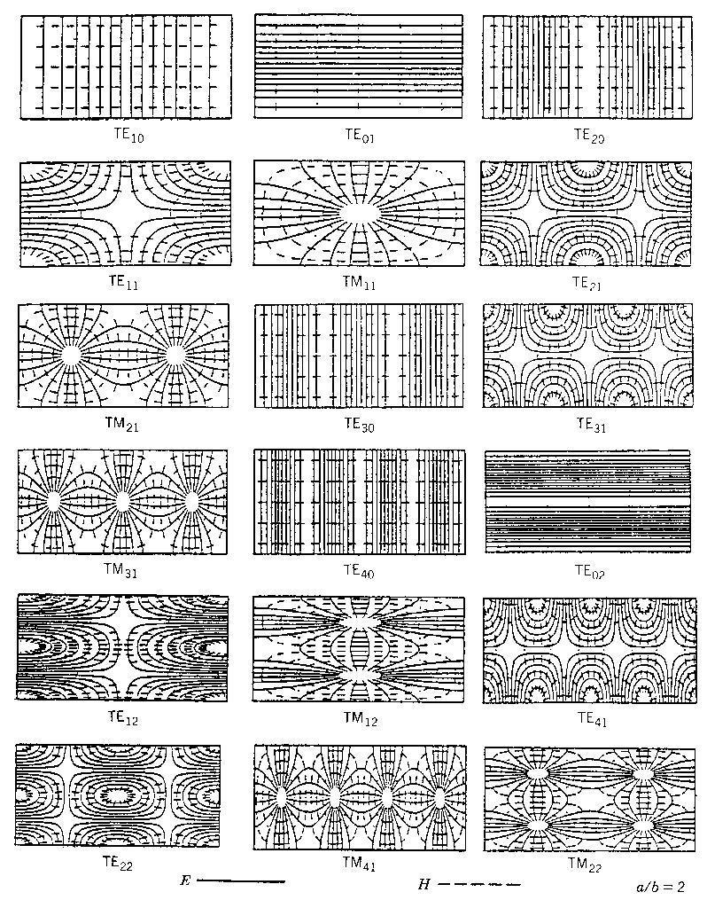
10 MODES:
11 6. Cylindrical waveguides: Cylindrical waveguide Using the complete formulation in the simplest limit possible, global electromagnetic modes are here studied in a large aspect ratio, circular cross-section vacuum cavity equivalent to a cylindrical waveguide. Classical electrodynamics show that the EM eigenmode spectrum consists of two types of solutions, the transverse electric and the transverse magnetic polarizations with frequencies depending on l the radial and m the azimuthal mode numbers. These results are reproduced numerically to verify that the wave equations (16) can indeed be solved in the vacuum using standard LFEM and CFEM discretizations, without introducing spurious modes of numerical origin. It is also important to validate the numerical implementation using a simple test case, checking that the numerical solutions converge to the analytical values with rates expected from the order of the approximations. As the equilibrium merely produces the geometry and the mesh, the safety factor does not affect the eigen frequency spectrum; using a large value for, it is however possible to everywhere align with the axis of the cylinder and separate the components of the TE and the TM polarizations. To compute the eigenmode spectrum, an oscillating source current (eq.22) is driven with a small imaginary part in the excitation frequency The power relation (eq.48) yields a complex response function which has poles along the real axis that correspond to the solutions of the discretized wave equations. The eigen frequencies are calculated by scanning in the complex plane with an increment and a constant chosen so as to resolve the response peaks in. The structure of an eigenmode is obtained in the limit when the cavity is resonantly excited at the maximum of a narrow response peak. In order to verify that the eigenfrequency spectrum of this cylindrical waveguide is complete and does not contain any spurious ''polluting`` mode, two broad scans are performed from 10 khz to 10 GHz with a high resolution in frequency and a low resolution in space for LFEM, for CFEM). All the Fourier modes representable by the numerical discretization are excited with azimuthal currents for TE modes, and axial currents for TM modes. Fig.6 summarizes the result obtained with LFEM, showing that every mode found numerically could be identified in a one to one correspondence with the analytical result. Modes which have low quantum numbers (l,m) are, as expected, obtained with a better precision; pushing the resolution to the lowest limit of 2 mesh points per wavelength (m=4), the deviations become of course important, but the spectrum remains unpolluted (remember fig.3, root b). The same analysis has been repeated with CFEM and leads to results which are much more precise. As an illustration, the eigenmode has here been calculated on a coarse homogeneous mesh. The eigenfrequency obtained numerically GHz is in excellent agreement with the analytical result = GHz; fig.5 shows the eigenmode structure in a vector plot of.
 A rectangular waveguide with both ends (z=0 and z=d) closed by a conducting wall (Figure 9-8) :")
12 Analytical (circles) and LFEM (x-marks) eigen frequency spectrum. 7. Rectangular cavity resonator: Cavity resonators are enclosed metal boxes. Electromagnetic fields are confined inside the boxes. Radiation and high-resistance effects are eliminated, resulting in a very high Q (quality factor) A rectangular waveguide with both ends (z=0 and z=d) closed by a conducting wall (Figure 9-8) : multiple reflections and standing waves
13 Resonant frequency of rectangular cavity resonator Degenerate modes : different modes having the same resonant frequency. Dominant mode : the mode with the lowest resonant frequency for a given cavity size. A resonator is a device or system that exhibits resonance or resonant behavior, that is, it naturally oscillates at some frequencies, called its resonant frequencies, with greater amplitude than at others. The oscillations in a resonator can be either electromagnetic or mechanical (including acoustic). Resonators are used to either generate waves of specific frequencies or to select specific frequencies from a signal. Musical instruments use acoustic resonators that produce sound waves of specific tones. A cavity resonator, usually used in reference to electromagnetic resonators, is one in which waves exist in a hollow space inside the device. Acoustic cavity resonators, in which sound is produced by air vibrating in a cavity with one opening, are known as Helmholtz resonators. 8. Principles Cavity resonators: Cavity resonators A cavity resonator is a hollow conductor blocked at both ends and along which an electromagnetic wave can be supported. It can be viewed as a waveguide short-circuited at both ends (see Microwave cavity). The cavity has interior surfaces which reflect a wave of a specific frequency. When a wave that is resonant with the cavity enters, it bounces back and forth within the cavity, with low loss (see standing wave). As more wave energy enters the cavity, it combines with and reinforces the standing wave, increasing its intensity. The cavity magnetron is a vacuum tube with a filament in the center of an evacuated, lobed, circular cavity resonator. A perpendicular magnetic field is imposed by a permanent magnet. The magnetic field causes the electrons, attracted to the (relatively) positive outer part of the chamber, to spiral outward in a circular path rather than moving directly to this anode. Spaced about the rim of the chamber are cylindrical cavities. The cavities are open along their length and so connect the common cavity space. As electrons sweep past these openings they induce a resonant high frequency radio field in the cavity, which in turn causes the electrons to bunch into groups. A portion of this field is extracted with a short antenna that is connected to a waveguide (a metal tube usually of rectangular cross section). The waveguide directs the extracted RF energy to the load, which may be a cooking chamber in a microwave oven or a high gain antenna in the case of radar. The klystron, tube waveguide, is a beam tube including at least two apertured cavity resonators. The beam of charged particles passes through the apertures of the resonators, often tunable wave reflection grids, in succession. A collector electrode is provided to intercept the beam after passing through the resonators. The first resonator causes bunching of the particles passing through it. The bunched particles travel in a field-free region where further bunching occurs, then the bunched particles enter the second resonator giving up their energy to excite it into oscillations. It is a particle accelerator that works in conjunction with a specifically tuned cavity by the configuration of the structures. On the beam line of an accelerator system, there are specific sections that are cavity resonators for RF. The reflex klystron is a klystron utilizing only a single apertured cavity resonator through which the beam of charged particles passes, first in one direction. A repeller electrode is provided to repel (or redirect) the beam after passage through the resonator back through the resonator in the other direction and in proper phase to reinforce the oscillations set up in the resonator.
14 In a laser, light is amplified in a cavity resonator which is usually composed of two or more mirrors. Thus an optical cavity, also known as a resonator, is a cavity with walls which reflect electromagnetic waves (light). This will allow standing wave modes to exist with little loss outside the cavity.
15
16
17


18 MAHALAKSHMI ENGINEERING COLLEGE TIRUCHIRAPALLI EC 2305 TRANSMISSION LINES AND WAVEGUIDES -V SEM ECE
Waveguides. Metal Waveguides. Dielectric Waveguides
 Waveguides Waveguides, like transmission lines, are structures used to guide electromagnetic waves from point to point. However, the fundamental characteristics of waveguide and transmission line waves
Photograph of the rectangular waveguide components
 Waveguides Photograph of the rectangular waveguide components BACKGROUND A transmission line can be used to guide EM energy from one point (generator) to another (load). A transmission line can support
Waveguides GATE Problems
 Waveguides GATE Problems One Mark Questions. The interior of a 20 20 cm cm rectangular waveguide is completely 3 4 filled with a dielectric of r 4. Waves of free space wave length shorter than..can be
TOPIC 2 WAVEGUIDE AND COMPONENTS
 TOPIC 2 WAVEGUIDE AND COMPONENTS COURSE LEARNING OUTCOME (CLO) CLO1 Explain clearly the generation of microwave, the effects of microwave radiation and the propagation of electromagnetic in a waveguide
Projects in microwave theory 2009
 Electrical and information technology Projects in microwave theory 2009 Write a short report on the project that includes a short abstract, an introduction, a theory section, a section on the results and
Projects in microwave theory 2017
 Electrical and information technology Projects in microwave theory 2017 Write a short report on the project that includes a short abstract, an introduction, a theory section, a section on the results and
04th - 16th August, th International Nathiagali Summer College 1 CAVITY BASICS. C. Serpico
 39th International Nathiagali Summer College 1 CAVITY BASICS C. Serpico 39th International Nathiagali Summer College 2 Outline Maxwell equations Guided propagation Rectangular waveguide Circular waveguide
DESIGN AND FABRICATION OF CAVITY RESONATORS
 &2@?%3 DESIGN AND FABRICATION OF CAVITY RESONATORS CHAPTER 3 DESIGN AND FABRICATION OFCAVITY RESONATORS 3.1 Introduction In the cavity perturbation techniques, generally rectangular or cylindrical waveguide
EC Transmission Lines And Waveguides
 EC6503 - Transmission Lines And Waveguides UNIT I - TRANSMISSION LINE THEORY A line of cascaded T sections & Transmission lines - General Solution, Physical Significance of the Equations 1. Define Characteristic
INSTITUTE OF AERONAUTICAL ENGINEERING (Autonomous) Dundigal, Hyderabad
 Dundigal, Hyderabad") INSTITUTE OF AERONAUTICAL ENGINEERING (Autonomous) Dundigal, Hyderabad - 500 043 ELECTRONICS AND COMMUNICATION ENGINEERING TUTORIAL BANK Name : MICROWAVE ENGINEERING Code : A70442 Class : IV B. Tech I
INSTITUTE OF AERONAUTICAL ENGINEERING (Autonomous) Dundigal, Hyderabad - 500 043 ELECTRONICS AND COMMUNICATION ENGINEERING TUTORIAL BANK Name : MICROWAVE ENGINEERING Code : A70442 Class : IV B. Tech I
Microwave Engineering
 Microwave Circuits 1 Microwave Engineering 1. Microwave: 300MHz ~ 300 GHz, 1 m ~ 1mm. a. Not only apply in this frequency range. The real issue is wavelength. Historically, as early as WWII, this is the
Γ L = Γ S =
 TOPIC: Microwave Circuits Q.1 Determine the S parameters of two port network consisting of a series resistance R terminated at its input and output ports by the characteristic impedance Zo. Q.2 Input matching
Fiber Optic Communication Systems. Unit-04: Theory of Light. https://sites.google.com/a/faculty.muet.edu.pk/abdullatif
 Unit-04: Theory of Light https://sites.google.com/a/faculty.muet.edu.pk/abdullatif Department of Telecommunication, MUET UET Jamshoro 1 Limitations of Ray theory Ray theory describes only the direction
Microwave and optical systems Introduction p. 1 Characteristics of waves p. 1 The electromagnetic spectrum p. 3 History and uses of microwaves and
 Microwave and optical systems Introduction p. 1 Characteristics of waves p. 1 The electromagnetic spectrum p. 3 History and uses of microwaves and optics p. 4 Communication systems p. 6 Radar systems p.
ELEC4604. RF Electronics. Experiment 2
 ELEC4604 RF Electronics Experiment MICROWAVE MEASUREMENT TECHNIQUES 1. Introduction and Objectives In designing the RF front end of a microwave communication system it is important to appreciate that the
(i) Determine the admittance parameters of the network of Fig 1 (f) and draw its - equivalent circuit.
 Determine the admittance parameters of the network of Fig 1 (f) and draw its - equivalent circuit.") I.E.S-(Conv.)-1995 ELECTRONICS AND TELECOMMUNICATION ENGINEERING PAPER - I Some useful data: Electron charge: 1.6 10 19 Coulomb Free space permeability: 4 10 7 H/m Free space permittivity: 8.85 pf/m Velocity
I.E.S-(Conv.)-1995 ELECTRONICS AND TELECOMMUNICATION ENGINEERING PAPER - I Some useful data: Electron charge: 1.6 10 19 Coulomb Free space permeability: 4 10 7 H/m Free space permittivity: 8.85 pf/m Velocity
R.K.YADAV. 2. Explain with suitable sketch the operation of two-cavity Klystron amplifier. explain the concept of velocity and current modulations.
 Question Bank DEPARTMENT OF ELECTRONICS AND COMMUNICATION SUBJECT- MICROWAVE ENGINEERING(EEC-603) Unit-III 1. What are the high frequency limitations of conventional tubes? Explain clearly. 2. Explain
Electromagnetic Wave Analysis of Waveguide and Shielded Microstripline 1 Srishti Singh 2 Anupma Marwaha
 Electromagnetic Wave Analysis of Waveguide and Shielded Microstripline 1 Srishti Singh 2 Anupma Marwaha M.Tech Research Scholar 1, Associate Professor 2 ECE Deptt. SLIET Longowal, Punjab-148106, India
EC TRANSMISSION LINES AND WAVEGUIDES TRANSMISSION LINES AND WAVEGUIDES
 TRANSMISSION LINES AND WAVEGUIDES UNIT I - TRANSMISSION LINE THEORY 1. Define Characteristic Impedance [M/J 2006, N/D 2006] Characteristic impedance is defined as the impedance of a transmission line measured
Monoconical RF Antenna
 Page 1 of 8 RF and Microwave Models : Monoconical RF Antenna Monoconical RF Antenna Introduction Conical antennas are useful for many applications due to their broadband characteristics and relative simplicity.
Split waveguide and a waveguide acting as an antenna
 2013-10-01 Department of Physics Olexii Iukhymenko oleksii.iukhymenko@physics.umu.se Computerlab 4 Split waveguide and a waveguide acting as an antenna Introduction: Split waveguide: Picture 1 This is
EC6503 Transmission Lines and WaveguidesV Semester Question Bank
 UNIT I TRANSMISSION LINE THEORY A line of cascaded T sections & Transmission lines General Solution, Physicasignificance of the equations 1. Derive the two useful forms of equations for voltage and current
Electromagnetics, Microwave Circuit and Antenna Design for Communications Engineering
 Electromagnetics, Microwave Circuit and Antenna Design for Communications Engineering Second Edition Peter Russer ARTECH HOUSE BOSTON LONDON artechhouse.com Contents Preface xvii Chapter 1 Introduction
THE ELECTROMAGNETIC FIELD THEORY. Dr. A. Bhattacharya
 1 THE ELECTROMAGNETIC FIELD THEORY Dr. A. Bhattacharya The Underlying EM Fields The development of radar as an imaging modality has been based on power and power density It is important to understand some
Antennas and Propagation. Chapter 4: Antenna Types
 Antennas and Propagation : Antenna Types 4.4 Aperture Antennas High microwave frequencies Thin wires and dielectrics cause loss Coaxial lines: may have 10dB per meter Waveguides often used instead Aperture
THE circular rectangular (C-R) coaxial waveguide has
 coaxial waveguide has") 414 IEEE TRANSACTIONS ON MICROWAVE THEORY AND TECHNIQUES, VOL. 45, NO. 3, MARCH 1997 The Higher Order Modal Characteristics of Circular Rectangular Coaxial Waveguides Haiyin Wang, Ke-Li Wu, Senior Member,
414 IEEE TRANSACTIONS ON MICROWAVE THEORY AND TECHNIQUES, VOL. 45, NO. 3, MARCH 1997 The Higher Order Modal Characteristics of Circular Rectangular Coaxial Waveguides Haiyin Wang, Ke-Li Wu, Senior Member,
SRI VENKATESWARA COLLEGE OF ENGINEERING DEPARTMENT OF ELECTRONICS AND COMMUNICATION ENGINEERING Date : UNIVERSITY QUESTIONS AND ANSWERS
 SRI VENKATESWARA COLLEGE OF ENGINEERING DEPARTMENT OF ELECTRONICS AND COMMUNICATION ENGINEERING Date : 02.07.2015 UNIVERSITY QUESTIONS AND ANSWERS Subject : Transmission lines & Wave Guides Sub Code :
3. (a) Derive an expression for the Hull cut off condition for cylindrical magnetron oscillator. (b) Write short notes on 8 cavity magnetron [8+8]
![3. (a) Derive an expression for the Hull cut off condition for cylindrical magnetron oscillator. (b) Write short notes on 8 cavity magnetron [8+8]](/thumbs/73/68588725.jpg "3. (a) Derive an expression for the Hull cut off condition for cylindrical magnetron oscillator. (b) Write short notes on 8 cavity magnetron [8+8]") Code No: RR320404 Set No. 1 1. (a) Compare Drift space bunching and Reflector bunching with the help of Applegate diagrams. (b) A reflex Klystron operates at the peak of n=1 or 3 / 4 mode. The dc power
Code No: RR320404 Set No. 1 1. (a) Compare Drift space bunching and Reflector bunching with the help of Applegate diagrams. (b) A reflex Klystron operates at the peak of n=1 or 3 / 4 mode. The dc power
Lec7 Transmission Lines and waveguides (II)
") Lec7 Transmission Lines and waveguides (II) 3.4 CIRCULAR WAVEGUIDE A hollow, round metal pipe also supports TE and TM waveguide modes. we can derive the cylindrical components of the transverse fields
Lec7 Transmission Lines and waveguides (II) 3.4 CIRCULAR WAVEGUIDE A hollow, round metal pipe also supports TE and TM waveguide modes. we can derive the cylindrical components of the transverse fields
Supplementary Figures
 Supplementary Figures Supplementary Figure 1 EM wave transport through a 150 bend. (a) Bend of our PEC-PMC waveguide. (b) Bend of the conventional PEC waveguide. Waves are incident from the lower left
COAXIAL / CIRCULAR HORN ANTENNA FOR A STANDARD
 COAXIAL / CIRCULAR HORN ANTENNA FOR 802.11A STANDARD Petr Všetula Doctoral Degree Programme (1), FEEC BUT E-mail: xvsetu00@stud.feec.vutbr.cz Supervised by: Zbyněk Raida E-mail: raida@feec.vutbr.cz Abstract:
MICROWAVE ENGINEERING LAB VIVA QUESTIONS AND ANSWERS
 MICROWAVE ENGINEERING LAB VIVA QUESTIONS AND ANSWERS. Why can t conventional tubes be used at microwave frequencies? Conventional tubes can t be used at microwave frequencies because of transit time effect.
 VALLIAMMAI ENGINEERING COLLEGE SRM Nagar, Kattankulathur-603 203 DEPARTMENT OF ELECTRONICS AND COMMUNICATION ENGINEERING EC6503 TRANSMISSION LINES AND WAVEGUIDES YEAR / SEMESTER: III / V ACADEMIC YEAR:
Aperture Antennas. Reflectors, horns. High Gain Nearly real input impedance. Huygens Principle
 Antennas 97 Aperture Antennas Reflectors, horns. High Gain Nearly real input impedance Huygens Principle Each point of a wave front is a secondary source of spherical waves. 97 Antennas 98 Equivalence
Standing waves. Consider a string with 2 waves of equal amplitude moving in opposite directions. or, if you prefer cos T
 Waves 2 1. Standing waves 2. Transverse waves in nature: electromagnetic radiation 3. Polarisation 4. Dispersion 5. Information transfer and wave packets 6. Group velocity 1 Standing waves Consider a string
High Power, Magnet-free, Waveguide Based Circulator Using Angular-Momentum Biasing of a Resonant Ring
 SLAC-R-1080 High Power, Magnet-free, Waveguide Based Circulator Using Angular-Momentum Biasing of a Resonant Ring Jeffrey Neilson and Emilio Nanni August 18, 2017 Prepared for Calabazas Creek Research,
UNIT Explain the radiation from two-wire. Ans: Radiation from Two wire
 UNIT 1 1. Explain the radiation from two-wire. Radiation from Two wire Figure1.1.1 shows a voltage source connected two-wire transmission line which is further connected to an antenna. An electric field
Experiment-4 Study of the characteristics of the Klystron tube
 Experiment-4 Study of the characteristics of the Klystron tube OBJECTIVE To study the characteristics of the reflex Klystron tube and to determine the its electronic tuning range EQUIPMENTS Klystron power
2/18/ Transmission Lines and Waveguides 1/3. and Waveguides. Transmission Line A two conductor structure that can support a TEM wave.
 2/18/2009 3 Transmission Lines and Waveguides 1/3 Chapter 3 Transmission Lines and Waveguides First, some definitions: Transmission Line A two conductor structure that can support a TEM wave. Waveguide
EC ANTENNA AND WAVE PROPAGATION
 EC6602 - ANTENNA AND WAVE PROPAGATION FUNDAMENTALS PART-B QUESTION BANK UNIT 1 1. Define the following parameters w.r.t antenna: i. Radiation resistance. ii. Beam area. iii. Radiation intensity. iv. Directivity.
St.MARTIN S ENGINEERING COLLEGE Dhulapally, Secunderabad
 St.MARTIN S ENGINEERING COLLEGE Dhulapally, Secunderabad 500014. Department of Electronics and Communication Engineering SUB: MICROWAVE ENGINEERING SECTION: ECE IV A & B NAME OF THE FACULTY: S RAVI KUMAR,T.SUDHEER
AM BASIC ELECTRONICS TRANSMISSION LINES JANUARY 2012 DEPARTMENT OF THE ARMY MILITARY AUXILIARY RADIO SYSTEM FORT HUACHUCA ARIZONA
 AM 5-306 BASIC ELECTRONICS TRANSMISSION LINES JANUARY 2012 DISTRIBUTION RESTRICTION: Approved for Pubic Release. Distribution is unlimited. DEPARTMENT OF THE ARMY MILITARY AUXILIARY RADIO SYSTEM FORT HUACHUCA
arxiv:physics/ v1 [physics.optics] 28 Sep 2005
![arxiv:physics/ v1 [physics.optics] 28 Sep 2005](/thumbs/91/105523130.jpg "arxiv:physics/ v1 [physics.optics] 28 Sep 2005") Near-field enhancement and imaging in double cylindrical polariton-resonant structures: Enlarging perfect lens Pekka Alitalo, Stanislav Maslovski, and Sergei Tretyakov arxiv:physics/0509232v1 [physics.optics]
Near-field enhancement and imaging in double cylindrical polariton-resonant structures: Enlarging perfect lens Pekka Alitalo, Stanislav Maslovski, and Sergei Tretyakov arxiv:physics/0509232v1 [physics.optics]
System Level Implementation of Cylindrical Dielectric Resonator Antenna for High Speed Real-time Applications Using Novel Mathematical Framework
 System Level Implementation of Cylindrical Dielectric Resonator Antenna for High Speed Real-time Applications Dr. S. V. A. V Prasad, Anshu Thakur Abstract With the advancements in the field of communication
High acceleration gradient. Critical applications: Linear colliders e.g. ILC X-ray FELs e.g. DESY XFEL
 High acceleration gradient Critical applications: Linear colliders e.g. ILC X-ray FELs e.g. DESY XFEL Critical points The physical limitation of a SC resonator is given by the requirement that the RF magnetic
Practical Measurements of Dielectric Constant and Loss for PCB Materials at High Frequency
 8 th Annual Symposium on Signal Integrity PENN STATE, Harrisburg Center for Signal Integrity Practical Measurements of Dielectric Constant and Loss for PCB Materials at High Frequency Practical Measurements
The Basics of Patch Antennas, Updated
 The Basics of Patch Antennas, Updated By D. Orban and G.J.K. Moernaut, Orban Microwave Products www.orbanmicrowave.com Introduction This article introduces the basic concepts of patch antennas. We use
WIRELESS power transfer through coupled antennas
 3442 IEEE TRANSACTIONS ON ANTENNAS AND PROPAGATION, VOL. 58, NO. 11, NOVEMBER 2010 Fundamental Aspects of Near-Field Coupling Small Antennas for Wireless Power Transfer Jaechun Lee, Member, IEEE, and Sangwook
EC 1402 Microwave Engineering
 SHRI ANGALAMMAN COLLEGE OF ENGINEERING & TECHNOLOGY (An ISO 9001:2008 Certified Institution) SIRUGANOOR,TRICHY-621105. DEPARTMENT OF ELECTRONICS AND COMMUNICATION ENGINEERING EC 1402 Microwave Engineering
Design of Frequency Selective Surface Radome over a Frequency Range
 Vol.2, Issue.3, May-June 2012 pp-1231-1236 ISSN: 2249-6645 Design of Frequency Selective Surface Radome over a Frequency Range K. Renu 1, K.V. V. Prasad 2, S. Saradha Rani 3, A. Gayatri 4 1, 3, 4 (Department
Rectangular waveguides
 Introduction Rectangular waveguides Waveguides are transmission lines commonly used in electronics, especially in higher frequency ranges like microwaves. A waveguide can be simply described as a metal
Magnetron. Physical construction of a magnetron
 anode block interaction space cathode filament leads Magnetron The magnetron is a high-powered vacuum tube that works as self-excited microwave oscillator. Crossed electron and magnetic fields are used
Useful general references for this experiment are Cheng [1], and Ramo et al [2].
![Useful general references for this experiment are Cheng [1], and Ramo et al [2].](/thumbs/74/70212276.jpg "Useful general references for this experiment are Cheng [1], and Ramo et al [2].") Experiment 7. Wave Propagation Updated RWH 21 August 2012 1 Aim In this experiment you will measure the radiation pattern of a half-wave dipole antenna, determine the resonant frequencies of a microwave
Experiment 7. Wave Propagation Updated RWH 21 August 2012 1 Aim In this experiment you will measure the radiation pattern of a half-wave dipole antenna, determine the resonant frequencies of a microwave
ECSE 352: Electromagnetic Waves
 December 2008 Final Examination ECSE 352: Electromagnetic Waves 09:00 12:00, December 15, 2008 Examiner: Zetian Mi Associate Examiner: Andrew Kirk Student Name: McGill ID: Instructions: This is a CLOSED
Experiment 12: Microwaves
 MASSACHUSETTS INSTITUTE OF TECHNOLOGY Department of Physics 8.02 Spring 2005 OBJECTIVES Experiment 12: Microwaves To observe the polarization and angular dependence of radiation from a microwave generator
1. Evolution Of Fiber Optic Systems
 OPTICAL FIBER COMMUNICATION UNIT-I : OPTICAL FIBERS STRUCTURE: 1. Evolution Of Fiber Optic Systems The operating range of optical fiber system term and the characteristics of the four key components of
Millimetre-wave Phased Array Antennas for Mobile Terminals
 Millimetre-wave Phased Array Antennas for Mobile Terminals Master s Thesis Alberto Hernández Escobar Aalborg University Department of Electronic Systems Fredrik Bajers Vej 7B DK-9220 Aalborg Contents
Critical Study of Open-ended Coaxial Sensor by Finite Element Method (FEM)
") International Journal of Applied Science and Engineering 3., 4: 343-36 Critical Study of Open-ended Coaxial Sensor by Finite Element Method (FEM) M. A. Jusoha*, Z. Abbasb, M. A. A. Rahmanb, C. E. Mengc,
International Journal of Applied Science and Engineering 3., 4: 343-36 Critical Study of Open-ended Coaxial Sensor by Finite Element Method (FEM) M. A. Jusoha*, Z. Abbasb, M. A. A. Rahmanb, C. E. Mengc,
Unit 5 Waveguides P a g e 1
 Unit 5 Waveguides P a g e Syllabus: Introduction, wave equation in Cartesian coordinates, Rectangular waveguide, TE, TM, TEM waves in rectangular guides, wave impedance, losses in wave guide, introduction
A Planar Equiangular Spiral Antenna Array for the V-/W-Band
 207 th European Conference on Antennas and Propagation (EUCAP) A Planar Equiangular Spiral Antenna Array for the V-/W-Band Paul Tcheg, Kolawole D. Bello, David Pouhè Reutlingen University of Applied Sciences,
9. Microwaves. 9.1 Introduction. Safety consideration
 MW 9. Microwaves 9.1 Introduction Electromagnetic waves with wavelengths of the order of 1 mm to 1 m, or equivalently, with frequencies from 0.3 GHz to 0.3 THz, are commonly known as microwaves, sometimes
Brief Overview of EM Computational Modeling Techniques for Real-World Engineering Problems
 Brief Overview of EM Computational Modeling Techniques for Real-World Engineering Problems Bruce Archambeault, Ph.D. IEEE Fellow, IBM Distinguished Engineer Emeritus Bruce@brucearch.com Archambeault EMI/EMC
Lecture 38: MON 24 NOV Ch.33 Electromagnetic Waves
 Physics 2113 Jonathan Dowling Heinrich Hertz (1857 1894) Lecture 38: MON 24 NOV Ch.33 Electromagnetic Waves Maxwell Equations in Empty Space: E da = 0 S B da = 0 S C C B ds = µ ε 0 0 E ds = d dt d dt S
ANTENNA INTRODUCTION / BASICS
 ANTENNA INTRODUCTION / BASICS RULES OF THUMB: 1. The Gain of an antenna with losses is given by: 2. Gain of rectangular X-Band Aperture G = 1.4 LW L = length of aperture in cm Where: W = width of aperture
CHAPTER 2 MICROSTRIP REFLECTARRAY ANTENNA AND PERFORMANCE EVALUATION
 43 CHAPTER 2 MICROSTRIP REFLECTARRAY ANTENNA AND PERFORMANCE EVALUATION 2.1 INTRODUCTION This work begins with design of reflectarrays with conventional patches as unit cells for operation at Ku Band in
ANALYSIS OF EPSILON-NEAR-ZERO METAMATE- RIAL SUPER-TUNNELING USING CASCADED ULTRA- NARROW WAVEGUIDE CHANNELS
 Progress In Electromagnetics Research M, Vol. 14, 113 121, 21 ANALYSIS OF EPSILON-NEAR-ZERO METAMATE- RIAL SUPER-TUNNELING USING CASCADED ULTRA- NARROW WAVEGUIDE CHANNELS J. Bai, S. Shi, and D. W. Prather
Advanced Meshing Techniques
 Advanced Meshing Techniques Ansoft High Frequency Structure Simulator v10 Training Seminar P-1 Overview Initial Mesh True Surface Approximation Surface Approximation Operations Lambda Refinement Seeding
A Pin-Loaded Microstrip Patch Antenna with the Ability to Suppress Surface Wave Excitation
 Progress In Electromagnetics Research C, Vol. 62, 131 137, 2016 A Pin-Loaded Microstrip Patch Antenna with the Ability to Suppress Surface Wave Excitation Ayed R. AlAjmi and Mohammad A. Saed * Abstract
Chapter 3 Broadside Twin Elements 3.1 Introduction
 Chapter 3 Broadside Twin Elements 3. Introduction The focus of this chapter is on the use of planar, electrically thick grounded substrates for printed antennas. A serious problem with these substrates
Antenna Design: Simulation and Methods
 Antenna Design: Simulation and Methods Radiation Group Signals, Systems and Radiocommunications Department Universidad Politécnica de Madrid Álvaro Noval Sánchez de Toca e-mail: anoval@gr.ssr.upm.es Javier
SUPPLEMENTARY INFORMATION
 A full-parameter unidirectional metamaterial cloak for microwaves Bilinear Transformations Figure 1 Graphical depiction of the bilinear transformation and derived material parameters. (a) The transformation
RAJIV GANDHI COLLEGE OF ENGINEERING AND TECHNOLOGY Kirumampakkam,Puducherry DEPARTMENT OF ELECTRONICS AND COMMUNICATION ENGINEERING
 RAJIV GANDHI COLLEGE OF ENGINEERING AND TECHNOLOGY Kirumampakkam,Puducherry-607402 DEPARTMENT OF ELECTRONICS AND COMMUNICATION ENGINEERING QUESTION BANK FOR EC T55 - TRANSMISSION LINES AND WAVEGUIDES G.LAXMINARAYANAN,
A Mode Based Model for Radio Wave Propagation in Storm Drain Pipes
 PIERS ONLINE, VOL. 4, NO. 6, 008 635 A Mode Based Model for Radio Wave Propagation in Storm Drain Pipes Ivan Howitt, Safeer Khan, and Jumanah Khan Department of Electrical and Computer Engineering The
Mutual Coupling between Two Patches using Ideal High Impedance Surface
 International Journal of Electronics and Communication Engineering. ISSN 0974-2166 Volume 4, Number 3 (2011), pp. 287-293 International Research Publication House http://www.irphouse.com Mutual Coupling
L-BAND COPLANAR SLOT LOOP ANTENNA FOR INET APPLICATIONS
 L-BAND COPLANAR SLOT LOOP ANTENNA FOR INET APPLICATIONS Jeyasingh Nithianandam Electrical and Computer Engineering Department Morgan State University, 500 Perring Parkway, Baltimore, Maryland 5 ABSTRACT
Broadside - Coupled Split Ring Resonator (BC-SRR) Metamaterial-Like Slow-Wave Structure. Sabahattin C. Yurt
 Metamaterial-Like Slow-Wave Structure. Sabahattin C. Yurt") Department of Electrical & Computer Engineering MURI Teleconference Broadside - Coupled Split Ring Resonator (BC-SRR) Metamaterial-Like Slow-Wave Structure Sabahattin C. Yurt cyurt@unm.edu Sarita Prasad
Department of Electrical & Computer Engineering MURI Teleconference Broadside - Coupled Split Ring Resonator (BC-SRR) Metamaterial-Like Slow-Wave Structure Sabahattin C. Yurt cyurt@unm.edu Sarita Prasad
Characterization of the Electromagnetic Fields Inside a Wire Mesh Cage for Biotelemetry
 Marquette University e-publications@marquette Master's Theses (2009 -) Dissertations, Theses, and Professional Projects Characterization of the Electromagnetic Fields Inside a Wire Mesh Cage for Biotelemetry
Localization and Identifying EMC interference Sources of a Microwave Transmission Module
 Localization and Identifying EMC interference Sources of a Microwave Transmission Module Ph. Descamps 1, G. Ngamani-Njomkoue 2, D. Pasquet 1, C. Tolant 2, D. Lesénéchal 1 and P. Eudeline 2 1 LaMIPS, Laboratoire
KULLIYYAH OF ENGINEERING
 KULLIYYAH OF ENGINEERING DEPARTMENT OF ELECTRICAL & COMPUTER ENGINEERING ANTENNA AND WAVE PROPAGATION LABORATORY (ECE 4103) EXPERIMENT NO 3 RADIATION PATTERN AND GAIN CHARACTERISTICS OF THE DISH (PARABOLIC)
For the mechanical system of figure shown above:
 I.E.S-(Conv.)-00 ELECTRONICS AND TELECOMMUNICATION ENGINEERING PAPER - I Time Allowed: Three Hours Maximum Marks : 0 Candidates should attempt any FIVE questions. Some useful data: Electron charge : 1.6
EFFECT ON PERFORMANCE CHARACTERISTICS OF RECTANGULAR PATCH ANTENNA WITH VARYING HEIGHT OF DIELECTRIC COVER
 International Journal of Power Control Signal and Computation (IJPCSC) Vol. 2 No. 1 ISSN : 0976-268X EFFECT ON PERFORMANCE CHARACTERISTICS OF RECTANGULAR PATCH ANTENNA WITH VARYING HEIGHT OF DIELECTRIC
Microwave Cancer Therapy
 Page 1 of 9 RF and Microwave Models : Microwave Cancer Therapy Microwave Cancer Therapy Electromagnetic heating appears in a wide range of engineering problems and is ideally suited for modeling in COMSOL
Principles of Optics for Engineers
 Principles of Optics for Engineers Uniting historically different approaches by presenting optical analyses as solutions of Maxwell s equations, this unique book enables students and practicing engineers
Chapter 2. Fundamental Properties of Antennas. ECE 5318/6352 Antenna Engineering Dr. Stuart Long
 Chapter Fundamental Properties of Antennas ECE 5318/635 Antenna Engineering Dr. Stuart Long 1 IEEE Standards Definition of Terms for Antennas IEEE Standard 145-1983 IEEE Transactions on Antennas and Propagation
VALLIAMMAI ENGINEERING COLLEGE
 VALLIAMMAI ENGINEERING COLLEGE SRM Nagar, Kattankulathur 603 203 DEPARTMENT OF ELECTRONICS AND COMMUNICATION ENGINEERING QUESTION BANK V SEMESTER EC6503 TRANSMISSION LINES AND WAVEGUIDES Regulation 2013
Introduction: Planar Transmission Lines
 Chapter-1 Introduction: Planar Transmission Lines 1.1 Overview Microwave integrated circuit (MIC) techniques represent an extension of integrated circuit technology to microwave frequencies. Since four
MULTIMEDIA UNIVERSITY FACULTY OF ENGINEERING LAB SHEET
 MULTIMEDIA UNIVERSITY FACULTY OF ENGINEERING LAB SHEET ELECTROMAGNETIC THEORY EMF016 MW1 MICROWAVE FREQUENCY AND SWR MEASUREMENTS EM Theory Faculty of Engineering, Multimedia University 1 EXPERIMENT MW1:
ELECTROMAGNETIC COMPATIBILITY HANDBOOK 1. Chapter 8: Cable Modeling
 ELECTROMAGNETIC COMPATIBILITY HANDBOOK 1 Chapter 8: Cable Modeling Related to the topic in section 8.14, sometimes when an RF transmitter is connected to an unbalanced antenna fed against earth ground
A Simple Wideband Transmission Line Model
 A Simple Wideband Transmission Line Model Prepared by F. M. Tesche Holcombe Dept. of Electrical and Computer Engineering College of Engineering & Science 337 Fluor Daniel Building Box 34915 Clemson, SC
CHAPTER 6 CARBON NANOTUBE AND ITS RF APPLICATION
 CHAPTER 6 CARBON NANOTUBE AND ITS RF APPLICATION 6.1 Introduction In this chapter we have made a theoretical study about carbon nanotubes electrical properties and their utility in antenna applications.
A NOVEL DUAL-BAND PATCH ANTENNA FOR WLAN COMMUNICATION. E. Wang Information Engineering College of NCUT China
 Progress In Electromagnetics Research C, Vol. 6, 93 102, 2009 A NOVEL DUAL-BAND PATCH ANTENNA FOR WLAN COMMUNICATION E. Wang Information Engineering College of NCUT China J. Zheng Beijing Electro-mechanical
RF AND MICROWAVE ENGINEERING
 RF AND MICROWAVE ENGINEERING FUNDAMENTALS OF WIRELESS COMMUNICATIONS Frank Gustrau Dortmund University of Applied Sciences and Arts, Germany WILEY A John Wiley & Sons, Ltd., Publication Preface List of
Antennas 1. Antennas
 Antennas Antennas 1! Grading policy. " Weekly Homework 40%. " Midterm Exam 30%. " Project 30%.! Office hour: 3:10 ~ 4:00 pm, Monday.! Textbook: Warren L. Stutzman and Gary A. Thiele, Antenna Theory and
Chapter 13: Microwave Communication Systems
 Chapter 13: Microwave Communication Systems Chapter 13 Objectives At the conclusion of this chapter, the reader will be able to: Describe the differences between microwave and lower-frequency communications
Fiber Optic Communications Communication Systems
 INTRODUCTION TO FIBER-OPTIC COMMUNICATIONS A fiber-optic system is similar to the copper wire system in many respects. The difference is that fiber-optics use light pulses to transmit information down
INTRODUCTION OF WAVEGUIDES
 INTRODUCTION OF WAVEGUIDES Under guidance of Joydeep Sengupta sir VNIT BT14ECE031 CHARAN SAI KATAKAM 1 INTRODUCTION TO WAVEGUIDES In a waveguide energy is transmitted in the form of electromagnetic waves
Accuracy of Microwave Cavity Perturbation Measurements
 918 IEEE TRANSACTIONS ON MICROWAVE THEORY AND TECHNIQUES, VOL. 49, NO. 5, MAY 2001 Accuracy of Microwave Cavity Perturbation Measurements Richard G. Carter, Member, IEEE Abstract Techniques based on the
Lecture - 14 Microwave Resonator
 Basic Building Blocks of Microwave Engineering Prof Amitabha Bhattacharya Department of Electronics and Communication Engineering Indian Institute of Technology, Kharagpur Lecture - 14 Microwave Resonator
Green s Function Expansions in Cylindrical Waves and Its Rigorous Source Singularity Evaluation for Full-Wave Analysis of SIW Radiating Structures
 Introduction Green s Function Expansions in Cylindrical Waves and Its Rigorous Source Singularity Evaluation for Full-Wave Analysis of SIW Radiating Structures Final Report By Guido Valerio Substrate Integrated
A MODIFIED FRACTAL RECTANGULAR CURVE DIELECTRIC RESONATOR ANTENNA FOR WIMAX APPLICATION
 Progress In Electromagnetics Research C, Vol. 12, 37 51, 2010 A MODIFIED FRACTAL RECTANGULAR CURVE DIELECTRIC RESONATOR ANTENNA FOR WIMAX APPLICATION R. K. Gangwar and S. P. Singh Department of Electronics