New SLED 3 system for Multi-mega Watt RF compressor. Chen Xu, Juwen Wang, Sami Tantawi
|
|
|
- Berenice Perkins
- 6 years ago
- Views:
Transcription
1 New SLED 3 system for Multi-mega Watt RF compressor Chen Xu, Juwen Wang, Sami Tantawi SLAC National Accelerator Laboratory, Stanford University, Stanford, CA 94309, USA Electronic address: chenxu@slac.stanford.edu Abstract A compact X band SLED is introduced for X band RF compressing application. This SLED compressor consists two major parts: a rectangular to circular waveguide converter and an overmoded spherical cavity. The RF compressor is designed to convert 50 magawatt X band RF power with pulse length 1.5 microseconds and deliver 200 megawatts with pulse length 106 nanoseconds to the X band accelerating structure. 1. Introduction SLAC has successfully designed and utilized X band and S band RF power compressor for NLC project and LCLS project. SLED is named as SLAC's Energy Doubling accelerating gradient. The conventional idea for SLED is that to store the first part energy of input RF pulse by cavities and releases the stored energy in cavities along with the second part of the pulse. Since the pulse power phase has been turned 180 degree, the output pulse is a combination in phase of the leakage power and input power. Thus, the pulse power is compressed and increased. Compression ratio, namely, the duration ratio between before and after compression is around 6. There are two critical points for this SLED technique: 1. The cavities must be over-coupled in order to obtain a output power higher than the original input power. 2. The pulse delivery network must be directional in order to combine leakage power and the flipped input pulse. The schematic system is shown in fig.1.

2 Fig.1. schematic drawing of the SLED microwave network. A 3db coupler is a four ports directional coupler. It is designed to convert a rectangular waveguide TE10 mode to equally feed two cavities without leakage to the fourth ports in fig.2. Fig.2. High power short slot hybrid 3db coupler. Moreover, when the power is leaked from these two cavities, the power from port 2 and 3 are canceling output to port 1 and combining output to port 4. This directional coupling characteristic is essential for the SLED technique. This conventional SLED utilized two single-moded pillbox cavities with quality factor around The cavity mode at 2.8GHz is TE015 mode. The mode has a pattern showing in fig.3. The mode has
3 Q~10 5 and coupling coefficient ( ~5), therefore, the loaded Q L is 90KHz and mode bandwidth is The whole structure is utilized in the current LCLS accelerator main linac, and it helps boosting the LCLS accelerated electron energy from 6GeV to 12GeV. However, the two bulky cavities and a 3 db coupler have size of 1.5m1.5m 1.5m for S band operation. Our goal is reduce its size and increasing the compression ratio to around 10. This goal yields higher compressed power and shorter output pulse for X band operation. 2. Design concept We recently design three versions of dual modes circular polarized couplers. These couplers can convert TE10 rectangular waveguide into two TE11 modes with different polarization in a circular waveguide. This over-moded structure can replace the conventional 3db couplers even though it only has three physical ports. The over-moded output can feed an overmoded cavity to avoid the second cavity in the conventional SLED design. Similarly, the modes inside this cavity will have the same, Q and degeneration frequency. An ideal candidate for this application is a spherical cavity. Spherical cavity has analytical solution for TE and TM modes. A TE mnp or TM mnp modes are labelled for azimuthal, polar and radial directions. The TE mnp field scalar potential is formulated in following. The field potential patterns are shown in Fig. 4. The electromagnetic field for TE mnp can be derived the equation below : E E H k F r 2 1 Fr 1 Fr H r sin r r E 2 2 r 0 r ( ) 2 r 2 1 Fr 1 Fr H r r sin r
4 Fig.4. The electromagnetic field pattern for TE 114 mode. Note these three modes have identical field pattern but different polarizations. In a spherical structure, the mode orientation is determined by the excitation signal from a give port. For example, dipole input feeds on the spherical cavity wall will coupling TE114 dipole modes. However, the TE014 cannot be excited by any dipole mode in a circular waveguide, thus this TE014 would have very small coupling. In order to avoid close neighbor modes and obtain higher Q 0, TEn14 modes are chosen. In this Ten14 family, there are three degeneration modes: one TE014 and two TE114 modes. When spherical cavity has a radius of cm, the TEn14 family has a degeneration frequency of GHz and the Q0 is around We need to design a coupler to this spherical cavity, and make large enough to obtain the maximum output. Assumed the traveling back wave accelerating structure to feed has a feeding time around 100ns, the gradient reaches maximum when is around 9. The outputs of the circular polarizer are from one circular waveguide, and each polarization mode in this waveguide is used to feed the different modes in the spherical cavity. Two single mode cavities is replaced by two polarization in one cavity, and spherical cavity and polarizer supple two modes and feeds with identical RF characteristics. 3. Characteristic of the dual circular polarizer and spherical ball design 3.1. Dual modes Circular converter The polarizer has three physical ports but the output circular waveguide supports two modes. These two TE11 modes have the same power magnitude, different polarization and 90 degree phase delay. Using this two TE11 circular modes to feeds two TE114 modes in the cavity, the input power are split into two cavity modes which canceling each other at the output rectangular waveguide. The scattering matrix for this structure is shown below:


5 The electric field on the surface of this structure is shown in Fig. 4. Fig.4: The complex magnitude of E field on coupler surface. This structure has a fairly wide RF operation bandwidth. The output of this coupler is a TE11 circular mode rotating on port 3. The frequency spectrum of scattering parameters is shown in Fig 5, and it shows that the port 1 has neither reflection nor a transmission, and all power equally split into two modes in port 3.
6 Fig.5. Scattering parameters frequency spectrum Spherical cavity design. The radius of a spherical cavity is cm when the resonating frequency is GHz. The unloaded Q is and an ideal goal is around 10. It is convenient to connect the spherical cavity directly with the circular waveguide. An iris is introduced to control the coupling. The larger iris radius will bring larger. While the operating frequency GHz is beyond the cutoff frequency of the circular waveguide, the waveguide with an iris can cut off the GHz field within the iris region. However, the thickness of this iris aperture is small, thus the evanescent TE11 mode can still couple into the cavity. By optimizing this thin iris, one can obtain the coupling coefficient around 10. Fig.6 shows the cavity E field on the surface of a given snapshot.


7 Fig.6 The snapshot of E field pattern at different frequency inside of the spherical cavity. Left is the TE014 mode and right is one polarized TE114 mode. The change of the iris radius can vary the coupling coefficient, because the leakage to the circular waveguide is determined by the level of cutoff at the iris region. A larger iris can increase, but the change is not a linear variation. Meanwhile, the TE114 resonating frequency is also change with change of the iris radius. The scattering parameters are swept at different frequency in Fig. 7 and of each resonating modes are calculated with different iris radius. 5.8mm
8 6.2mm
9 6.6mm 7mm 8mm
10 9.5mm Fig.7. the scattering matrix and Smith chart of each frequency sweep. Since the simulation from HFSS is in a steady state, one can extract of each iris radius setups from the scattering parameter by the equation. 1 S 1 S Smith charts are used to determine is under coupled or over coupled. The TE114 resonating frequency, scattering matrix and the dependency with the iris radius are shown in Fig8.
11 nim TE114 frequency vs Iris Scattering vs Iris
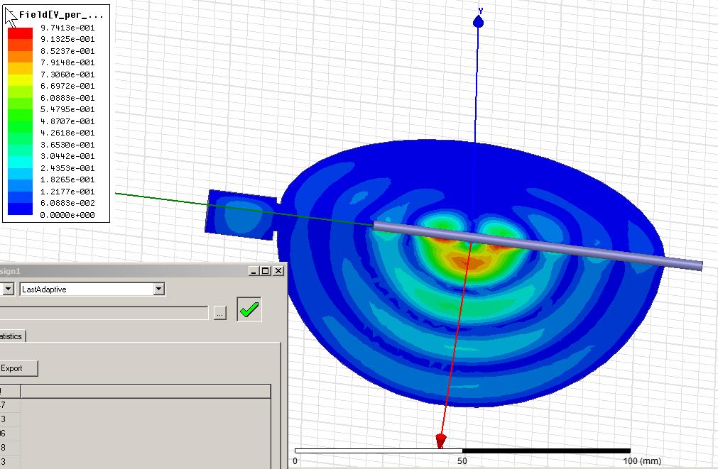
12 Beta vs Iris Fig.8, The resonating frequency, scattering matrix and dependency with the change of the iris radius. 3.3 Combination. A copper sheet with thickness of 5mm is machined to this structure. The geometry of this SLED is shown in Fig. 9. A snapshot of the surface E field is shown in Fig 10, and the input power from WR 90 is 1W. The peak E surface occurs at the waveguide, not on the surface of spherical cavity. When the input power is 50MW, the peak surface E field is 8.63MV/m.


13 Fig.9. the actual mechanical design of SLED system. 4. Frequency response, Transient response and Multi-physics concern. 4.1 Frequency response:
14 The cavity is simulated with frequency scan from GHz to GHz, and the frequency sweep is shown in Fig.7. Smith chart is also plotted in the fig.10. The center resonating peak suggests the two TE114 modes and the smaller peak on the right indicates the TE014 with very weak coupling. The TE114 modes have two polarizations, and the fields patterns are identical except the orientation. D Fig.10: The scattering parameters scan of driving frequency. 4.2 Transient response: Input pulse of this SLED compressor is a square pulse with a modulated rising time and at certain time duration, the input pulse phase is flipped 180 degree. The pulse is both plotted in time domain and frequency domain. The spectrum contains the center frequency and side band frequencies lobes and the cavity resonates at the center frequencies. After convoluting the cavity spectrum in Fig 7 with input pulse spectrum in fig.10, we inverse Fourier transform this output back to time domain and obtain an output with a compressed pulse in fig 11.
15 Fig.11: The scattering parameters scan of driving frequency.
16
17 Thermal concern: The SLED spherical cavity has fairly high Q0, thus the loss on the cavity wall is small compared with the energy stored in the cavity. The major RF loss is from the waveguide, and the power loss on the convertor and the system within a RF cycle is shown in Fig.12. The input power is normalized to 1W. The integrated RF surface loss are W and W respectively.

18 Fig. 12. RF loss distribution on the converter and the system. By using this RF loss as input load, ANSYS workbench is used to calculate temperature rise on the copper internal surface. Note, the SLED is operated in a pulse mode, and the repetition rate of an X band klystron is 120hz and duty factor is This means the HFSS result which is a CW calculation needs to multiply this duty factor to obtain averaged RF loss. A steady thermal calculation is simulated in ANSYS. The temperature distribution on the internal surface is illustrated in Fig. 13. Fig. 13. Temperature distribution on the system and the mode convertor. 4.4 Mechanical concern: The cavity has two resonating modes and the total Q0 is the same as the individual Q0 because the two modes are identical. The loaded Q is about one tenth of the Q0 and QL is around The Lorentz force on the cavity wall can be calculated locally with equation: surface P E H The electric field acts as an attractive force and magnetic field acts a repulsively force. The combination pressure on surface causes the deformation of the spherical cavity and leads to frequency detuned. To avoid this, a mechanical enhancement is added to support the exterior. The force and deformation on the surface are shown in the Fig. 14.
19 Fig.14. Surface force and deformation with input power 1W. The detune frequency of spherical cavity is formulated in equation below: 0 Um U U 0 e Assumed the is 10 and the input power is 50MW, and that make the power loss P d P f on the wall is 16MW at steady state, thus the stored energy U PQ d L is around at 2.2 Joule at peak charge. The typical coefficient to quantify this frequency tuning is Hz/(MV/m) 2. As stated above, when the ratio between max E surface field over input power is about 3500V/mW. Thus, the tuning coefficient is Hz/W. We need a tuning range of MHz to operate 50MW on this SLED. 4.5 Tuning capability and Multipacting: The cavity requires a tuning system to accurately adjust resonating frequency to GHz. As stated above, the frequency will be tuned with stored energy, and we need a frequency tuner with a frequency range around 20Mhz. A waveguide with a plunger can be an ideal tuner. One can use either a circular waveguide with propagating or evanescent TE11 mode to tune this spherical cavity; however both tuners have different frequency variation range and tuning sensitivity. The setups of plunger tuners are demonstrated in Fig.15. A center rod with a stem is introduced to cut off the TE11 coaxial mode in the pipe for both tuners. It is necessary to implement a choke joint structure to prevent leakage in this coaxial for the propagating waveguide plunger. The space between two plates in Fig15b, is this choke, and the distance in between is a quarter of waveguide wavelength in the choke joint.


20 Fig.15. Setups of two waveguide plungers tuners. The frequency shift and changes are functions of the plunger location, and these dependencies are plotted in fig. 16 for both tuners. Fig.16. The resonating frequency of TE114 and coupling coefficient vs the waveguide plunger location. The x axis is the distance between the plunger head to the spherical cavity. For the evanescent waveguide plunger, a larger waveguide area will reduce more resonating TE114 frequency. When the plunger distance is larger than the evanescent delay length, the tuner approaches the lower tuning frequency limit. For the propagating waveguide case, tuner frequency shift resonates with the distance of plunger, and the oscillating period is the guided wavelength in the circular waveguide. Multipacting simulation is under further investigation for both plunger tuners.
21 5. Conclusion A novel compact SLED is introduced and designed. The RF and multi-physics simulation suggests that it can operate with input power of 50MW with pulse length of 1.5microseconds and output power of 150MW with pulse length 100ns. A prototype of this SLED is about to make and tested soon. Acknowledgement We would like to thank Dr David Farkas from SLAC national accelerating laboratory for some useful discussions. This work was supported by Department of Energy Contract No. DE-AC02-76SF Reference 1. H. Padamsee, J. Knobloch, and T. Hays, RF Superconductivity for Accelerators. 2nd Edition (Wiley and Sons, New York,NY, 2008). 2. W.-D. Moeller for the TESLA Collaboration, High Power Coupler For The TESLA Test Facility, Proceedings of the 9th Workshop on the RF Superconductivity, 1999, Santa Fe, V.2, pp J. R. Delayen, L.R. Doolittle, T. Hiatt, J. Hogan, J. Mammosser. An R.F. Input Coupler System For The CEBAF Energy Upgrade Cryomodule. Proceedings of the 1999 Particle Accelerator Conference, New York, pp S. Belomestnykh, et al., High Average Power Fundamental Input Couplers for the Cornell University ERL: Requirements, Design Challenges and First Ideas, Cornell LEPP Report ERL 02-8 (September 9, 2002). 5. RF windows 6. E. Snitzer. Cylindrical dielectric waveguide modes Journal of the Optical Society of America, Vol. 51, Issue 5, pp (1961) 7. Zaki, K.A. Atia, A.E. Modes in Dielectric-Loaded Waveguides and Resonators. Microwave Theory and Techniques, IEEE Transactions on V.31, I.12,1982. pp
22 8. Clarricoats, P.J.B. Properties of dielectric-rod junctions in circular waveguide, Electrical Engineers, Proceedings of the Institution of (Volume:111, Issue: 1 ) Pp Clarricoats, P.J.B. ; Taylor, B.C. Evanescent and propagating modes of dielectric-loaded circular waveguide. Electrical Engineers, Proceedings of the Institution of (Volume:111, Issue: 12 ) 1964 pp Walter M. Elsasser. Attenuation in a Dielectric Circular Rod. J. Appl. Phys. 20, 1193 (1949) 11. Rothwell, E.J. and Frasch, L.L. Propagation characteristics of dielectric-rodloaded waveguides.microwave Theory and Techniques, IEEE Transactions on (Volume:36, Issue: 3 ) pp Optics book 13. S.F.Mahmoud. Electromagnetics waveguides theory and applications. The Institution of Engineering and Technology (December 1991) 14. A.A. Mostafaa, C.M. Krowneb, K.A. Zakic & S. Tantawid Hybrid-Mode Fields in Isotropic and Anisotropic Planar Microstrip Structures. Journal of Electromagnetic Waves and Applications Volume 5, Issue 6, 1991 Appendix:
![i01 i01 -Cos[ 01] - e -Cos[ 01] + e Sin[ 01] 0 0 0 2 2 2 i02 i 02 -Cos[ 02] - e -Cos[ 02] + e Sin[ 02] 0 0 0 2 2 2 i01 i01 -Cos[ 01] + e -Cos[ 01] - e Sin[](/docs-images/71/65744138/images/23-0.jpg "01] 0 0 0 2 2 S 2 i02 i02 -Cos[ 02] + e -Cos[ 02] - e Sin[ 02] 0 0 0 2 2 2 Sin[ 01] Sin[ 01] 0 0 Cos[ 01] 0 2 2 Sin[ 02] Sin[ 02] 0 0 0 Cos[ 02] 2 2 Table")
23 i01 i01 -Cos[ 01] - e -Cos[ 01] + e Sin[ 01] i02 i 02 -Cos[ 02] - e -Cos[ 02] + e Sin[ 02] i01 i01 -Cos[ 01] + e -Cos[ 01] - e Sin[ 01] S 2 i02 i02 -Cos[ 02] + e -Cos[ 02] - e Sin[ 02] Sin[ 01] Sin[ 01] 0 0 Cos[ 01] Sin[ 02] Sin[ 02] Cos[ 02] 2 2 Table 5
24
25
Conceptual Design Of An Ideal Variable Coupler For Superconducting Radiofrequency 1.3GHz Cavities. Chen Xu, Sami Tantawi
 Conceptual Design Of An Ideal Variable Coupler For Superconducting Radiofrequency 1.3GHz Cavities. Chen Xu, Sami Tantawi Stanford Linear Accelerator Center, Stanford University, 2575 Sand Hill Road, Menlo
The Next Linear Collider Test Accelerator s RF Pulse Compression and Transmission Systems
 SLAC-PUB-7247 February 1999 The Next Linear Collider Test Accelerator s RF Pulse Compression and Transmission Systems S. G. Tantawi et al. Presented at the 5th European Particle Accelerator Conference
Performance Measurements of SLAC's X-band. High-Power Pulse Compression System (SLED-II)
") SLAC PUB 95-6775 June 995 Performance Measurements of SLAC's X-band High-Power Pulse Compression System (SLED-II) Sami G. Tantawi, Arnold E. Vlieks, and Rod J. Loewen Stanford Linear Accelerator Center
SLAC PUB 95-6775 June 995 Performance Measurements of SLAC's X-band High-Power Pulse Compression System (SLED-II) Sami G. Tantawi, Arnold E. Vlieks, and Rod J. Loewen Stanford Linear Accelerator Center
High Power, Magnet-free, Waveguide Based Circulator Using Angular-Momentum Biasing of a Resonant Ring
 SLAC-R-1080 High Power, Magnet-free, Waveguide Based Circulator Using Angular-Momentum Biasing of a Resonant Ring Jeffrey Neilson and Emilio Nanni August 18, 2017 Prepared for Calabazas Creek Research,
Christopher Nantista ISG-X SLAC June 17, 2003
 Christopher Nantista ISG-X SLAC June 17, 2003 8-Pack Phase II NLC/JGLC R2 requirement: a linac subunit test rf power distribution dual-moded SLED-II eight 60cm structures Goals: Transport several hundred
Development of a 20-MeV Dielectric-Loaded Accelerator Test Facility
 SLAC-PUB-11299 Development of a 20-MeV Dielectric-Loaded Accelerator Test Facility S.H. Gold, et al. Contributed to 11th Advanced Accelerator Concepts Workshop (AAC 2004), 06/21/2004--6/26/2004, Stony
Projects in microwave theory 2017
 Electrical and information technology Projects in microwave theory 2017 Write a short report on the project that includes a short abstract, an introduction, a theory section, a section on the results and
Design, Development and Testing of RF Window for C band 250 kw CW Power Klystron
 Available online www.ejaet.com European Journal of Advances in Engineering and Technology, 2016, 3(6): 26-30 Research Article ISSN: 2394-658X Design, Development and Testing of RF Window for C band 250
International Technology Recommendation Panel. X-Band Linear Collider Path to the Future. RF System Overview. Chris Adolphsen
 International Technology Recommendation Panel X-Band Linear Collider Path to the Future RF System Overview Chris Adolphsen Stanford Linear Accelerator Center April 26-27, 2004 Delivering the Beam Energy
RF AND MICROWAVE ENGINEERING
 RF AND MICROWAVE ENGINEERING FUNDAMENTALS OF WIRELESS COMMUNICATIONS Frank Gustrau Dortmund University of Applied Sciences and Arts, Germany WILEY A John Wiley & Sons, Ltd., Publication Preface List of
L-BAND COPLANAR SLOT LOOP ANTENNA FOR INET APPLICATIONS
 L-BAND COPLANAR SLOT LOOP ANTENNA FOR INET APPLICATIONS Jeyasingh Nithianandam Electrical and Computer Engineering Department Morgan State University, 500 Perring Parkway, Baltimore, Maryland 5 ABSTRACT
Waveguides. Metal Waveguides. Dielectric Waveguides
 Waveguides Waveguides, like transmission lines, are structures used to guide electromagnetic waves from point to point. However, the fundamental characteristics of waveguide and transmission line waves
ELEC4604. RF Electronics. Experiment 2
 ELEC4604 RF Electronics Experiment MICROWAVE MEASUREMENT TECHNIQUES 1. Introduction and Objectives In designing the RF front end of a microwave communication system it is important to appreciate that the
R.K.YADAV. 2. Explain with suitable sketch the operation of two-cavity Klystron amplifier. explain the concept of velocity and current modulations.
 Question Bank DEPARTMENT OF ELECTRONICS AND COMMUNICATION SUBJECT- MICROWAVE ENGINEERING(EEC-603) Unit-III 1. What are the high frequency limitations of conventional tubes? Explain clearly. 2. Explain
Projects in microwave theory 2009
 Electrical and information technology Projects in microwave theory 2009 Write a short report on the project that includes a short abstract, an introduction, a theory section, a section on the results and
DEVELOPMENT OF A BETA 0.12, 88 MHZ, QUARTER WAVE RESONATOR AND ITS CRYOMODULE FOR THE SPIRAL2 PROJECT
 DEVELOPMENT OF A BETA 0.12, 88 MHZ, QUARTER WAVE RESONATOR AND ITS CRYOMODULE FOR THE SPIRAL2 PROJECT G. Olry, J-L. Biarrotte, S. Blivet, S. Bousson, C. Commeaux, C. Joly, T. Junquera, J. Lesrel, E. Roy,
A Pin-Loaded Microstrip Patch Antenna with the Ability to Suppress Surface Wave Excitation
 Progress In Electromagnetics Research C, Vol. 62, 131 137, 2016 A Pin-Loaded Microstrip Patch Antenna with the Ability to Suppress Surface Wave Excitation Ayed R. AlAjmi and Mohammad A. Saed * Abstract
Evaluation of HOM Coupler Probe Heating by HFSS Simulation
 G. Wu, H. Wang, R. A. Rimmer, C. E. Reece Abstract: Three different tip geometries in a HOM coupler on a CEBAF Upgrade Low Loss cavity have been evaluated by HFSS simulation to understand the tip surface
Coupler Electromagnetic Design
 Coupler Electromagnetic Design HPC Workshop, TJNAF October 30 November 1, 2002 Yoon Kang Spallation Neutron Source Oak Ridge National Laboratory Contents Fundamental Power Coupler Design Consideration
RF simulations with COMSOL
 RF simulations with COMSOL ICPS 217 Politecnico di Torino Aug. 1 th, 217 Gabriele Rosati gabriele.rosati@comsol.com 3 37.93.8 Copyright 217 COMSOL. Any of the images, text, and equations here may be copied
On the RF system of the ILC
 On the RF system of the ILC Sami G. Tantawi Chris Nantista Valery Dolgashev Jiquan Guo SLAC Outline This talk is a collection of thoughts about the rf system based on our experience with X-band system!
Design of a Novel Compact Cup Feed for Parabolic Reflector Antennas
 Progress In Electromagnetics Research Letters, Vol. 64, 81 86, 2016 Design of a Novel Compact Cup Feed for Parabolic Reflector Antennas Amir Moallemizadeh 1,R.Saraf-Shirazi 2, and Mohammad Bod 2, * Abstract
Electromagnetics, Microwave Circuit and Antenna Design for Communications Engineering
 Electromagnetics, Microwave Circuit and Antenna Design for Communications Engineering Second Edition Peter Russer ARTECH HOUSE BOSTON LONDON artechhouse.com Contents Preface xvii Chapter 1 Introduction
Normal-conducting high-gradient rf systems
 Normal-conducting high-gradient rf systems Introduction Motivation for high gradient Order of 100 GeV/km Operational and state-of-the-art SwissFEL C-band linac: Just under 30 MV/m CLIC prototypes: Over
CAGE CAVITY: A LOW COST, HIGH PERFORMANCE SRF ACCELERATING STRUCTURE*
 CAGE CAVITY: A LOW COST, HIGH PERFORMANCE SRF ACCELERATING STRUCTURE* J. Noonan, T.L. Smith, M. Virgo, G.J. Waldsmidt, Argonne National Laboratory J.W. Lewellen, Los Alamos National Laboratory Abstract
REVIEW OF HIGH POWER CW COUPLERS FOR SC CAVITIES. S. Belomestnykh
 REVIEW OF HIGH POWER CW COUPLERS FOR SC CAVITIES S. Belomestnykh HPC workshop JLAB, 30 October 2002 Introduction Many aspects of the high-power coupler design, fabrication, preparation, conditioning, integration
MICROWAVE MICROWAVE TRAINING BENCH COMPONENT SPECIFICATIONS:
 Microwave section consists of Basic Microwave Training Bench, Advance Microwave Training Bench and Microwave Communication Training System. Microwave Training System is used to study all the concepts of
Cavity BPMs for the NLC
 SLAC-PUB-9211 May 2002 Cavity BPMs for the NLC Ronald Johnson, Zenghai Li, Takashi Naito, Jeffrey Rifkin, Stephen Smith, and Vernon Smith Stanford Linear Accelerator Center, 2575 Sand Hill Road, Menlo
THE MULTIPACTING STUDY OF NIOBIUM SPUTTERED HIGH-BETA QUARTER-WAVE RESONATORS FOR HIE-ISOLDE
 THE MULTIPACTING STUDY OF NIOBIUM SPUTTERED HIGH-BETA QUARTER-WAVE RESONATORS FOR HIE-ISOLDE P. Zhang and W. Venturini Delsolaro CERN, Geneva, Switzerland Abstract Superconducting Quarter-Wave Resonators
30 GHz rf components for CTF3 (and CLIC) next part. I. Syratchev
 next part. I. Syratchev") 3 GHz rf components for CTF3 (and CLIC) next part I. Syratchev 3 GHz overmoded waveguide components (GYCOM, Russia) Mode converter 4.86x5 Taper Mitered bend.75.5 T 5 9.985 Measured losses per mode converter
3 GHz rf components for CTF3 (and CLIC) next part I. Syratchev 3 GHz overmoded waveguide components (GYCOM, Russia) Mode converter 4.86x5 Taper Mitered bend.75.5 T 5 9.985 Measured losses per mode converter
arxiv:physics/ v1 [physics.optics] 28 Sep 2005
![arxiv:physics/ v1 [physics.optics] 28 Sep 2005](/thumbs/91/105523130.jpg "arxiv:physics/ v1 [physics.optics] 28 Sep 2005") Near-field enhancement and imaging in double cylindrical polariton-resonant structures: Enlarging perfect lens Pekka Alitalo, Stanislav Maslovski, and Sergei Tretyakov arxiv:physics/0509232v1 [physics.optics]
Near-field enhancement and imaging in double cylindrical polariton-resonant structures: Enlarging perfect lens Pekka Alitalo, Stanislav Maslovski, and Sergei Tretyakov arxiv:physics/0509232v1 [physics.optics]
A DUAL-PORTED PROBE FOR PLANAR NEAR-FIELD MEASUREMENTS
 A DUAL-PORTED PROBE FOR PLANAR NEAR-FIELD MEASUREMENTS W. Keith Dishman, Doren W. Hess, and A. Renee Koster ABSTRACT A dual-linearly polarized probe developed for use in planar near-field antenna measurements
RF Design of Normal Conducting Deflecting Cavity
 RF Design of Normal Conducting Deflecting Cavity Valery Dolgashev (SLAC), Geoff Waldschmidt, Ali Nassiri (Argonne National Laboratory, Advanced Photon Source) 48th ICFA Advanced Beam Dynamics Workshop
RF STATUS OF SUPERCONDUCTING MODULE DEVELOPMENT SUITABLE FOR CW OPERATION: ELBE CRYOSTATS
 RF STATUS OF SUPERCONDUCTING MODULE DEVELOPMENT SUITABLE FOR CW OPERATION: ELBE CRYOSTATS J. Teichert, A. Büchner, H. Büttig, F. Gabriel, P. Michel, K. Möller, U. Lehnert, Ch. Schneider, J. Stephan, A.
3. (a) Derive an expression for the Hull cut off condition for cylindrical magnetron oscillator. (b) Write short notes on 8 cavity magnetron [8+8]
![3. (a) Derive an expression for the Hull cut off condition for cylindrical magnetron oscillator. (b) Write short notes on 8 cavity magnetron [8+8]](/thumbs/73/68588725.jpg "3. (a) Derive an expression for the Hull cut off condition for cylindrical magnetron oscillator. (b) Write short notes on 8 cavity magnetron [8+8]") Code No: RR320404 Set No. 1 1. (a) Compare Drift space bunching and Reflector bunching with the help of Applegate diagrams. (b) A reflex Klystron operates at the peak of n=1 or 3 / 4 mode. The dc power
Code No: RR320404 Set No. 1 1. (a) Compare Drift space bunching and Reflector bunching with the help of Applegate diagrams. (b) A reflex Klystron operates at the peak of n=1 or 3 / 4 mode. The dc power
HYBRID ARRAY ANTENNA FOR BROADBAND MILLIMETER-WAVE APPLICATIONS
 Progress In Electromagnetics Research, PIER 83, 173 183, 2008 HYBRID ARRAY ANTENNA FOR BROADBAND MILLIMETER-WAVE APPLICATIONS S. Costanzo, I. Venneri, G. Di Massa, and G. Amendola Dipartimento di Elettronica,
Physics Requirements Document Document Title: SCRF 1.3 GHz Cryomodule Document Number: LCLSII-4.1-PR-0146-R0 Page 1 of 7
 Document Number: LCLSII-4.1-PR-0146-R0 Page 1 of 7 Document Approval: Originator: Tor Raubenheimer, Physics Support Lead Date Approved Approver: Marc Ross, Cryogenic System Manager Approver: Jose Chan,
ABSTRACT 1 CEBAF UPGRADE CAVITY/CRYOMODULE
 Energy Content (Normalized) SC Cavity Resonance Control System for the 12 GeV Upgrade Cavity: Requirements and Performance T. Plawski, T. Allison, R. Bachimanchi, D. Hardy, C. Hovater, Thomas Jefferson
INSTITUTE OF AERONAUTICAL ENGINEERING (Autonomous) Dundigal, Hyderabad
 Dundigal, Hyderabad") INSTITUTE OF AERONAUTICAL ENGINEERING (Autonomous) Dundigal, Hyderabad - 500 043 ELECTRONICS AND COMMUNICATION ENGINEERING TUTORIAL BANK Name : MICROWAVE ENGINEERING Code : A70442 Class : IV B. Tech I
INSTITUTE OF AERONAUTICAL ENGINEERING (Autonomous) Dundigal, Hyderabad - 500 043 ELECTRONICS AND COMMUNICATION ENGINEERING TUTORIAL BANK Name : MICROWAVE ENGINEERING Code : A70442 Class : IV B. Tech I
Review of New Shapes for Higher Gradients
 Review of New Shapes for Higher Gradients Rong-Li Geng LEPP, Cornell University Rong-Li Geng SRF2005, July 10-15, 2005 1 1 TeV 800GeV 500GeV ILC(TESLA type) energy reach Rapid advances in single-cell cavities
Design of Rotman Lens Antenna at Ku-Band Based on Substrate Integrated Technology
 Journal of Communication Engineering, Vol. 3, No.1, Jan.- June 2014 33 Design of Rotman Lens Antenna at Ku-Band Based on Substrate Integrated Technology S. A. R. Hosseini, Z. H. Firouzeh and M. Maddahali
2 Theory of electromagnetic waves in waveguides and of waveguide components
 RF transport Stefan Choroba DESY, Hamburg, Germany Abstract This paper deals with the techniques of transport of high-power radiofrequency (RF) power from a RF power source to the cavities of an accelerator.
Christopher Nantista ISG8 SLAC June 25, 2002
 Christopher Nantista ISG8 SLAC June 25, 2002 TM 01 Mode Launcher Development Developed for upcoming traveling-wave single- structure tests as part of R&D to solve rf breakdown problem. Launchers to be
High Power Over-Mode 90 Bent Waveguides for Circular TM 01 and Coaxial TEM Mode Transmission
 Progress In Electromagnetics Research M, Vol. 60, 189 196, 2017 High Power Over-Mode 90 Bent Waveguides for Circular TM 01 and Coaxial TEM Mode Transmission Xiaomeng Li, Xiangqiang Li *, Qingxiang Liu,
A Millimeter Wave Center-SIW-Fed Antenna For 60 GHz Wireless Communication
 A Millimeter Wave Center-SIW-Fed Antenna For 60 GHz Wireless Communication M. Karami, M. Nofersti, M.S. Abrishamian, R.A. Sadeghzadeh Faculty of Electrical and Computer Engineering K. N. Toosi University
The European Spallation Source. Dave McGinnis Chief Engineer ESS\Accelerator Division IVEC 2013
 The European Spallation Source Dave McGinnis Chief Engineer ESS\Accelerator Division IVEC 2013 Overview The European Spallation Source (ESS) will house the most powerful proton linac ever built. The average
HIGH POWER INPUT COUPLERS FOR THE STF BASELINE CAVITY SYSTEM AT KEK
 HIGH POWER INPUT COUPLERS FOR THE STF BASELINE CAVITY SYSTEM AT KEK E. Kako #, H. Hayano, S. Noguchi, T. Shishido, K. Watanabe and Y. Yamamoto KEK, Tsukuba, Ibaraki, 305-0801, Japan Abstract An input coupler,
CHAPTER 2 MICROSTRIP REFLECTARRAY ANTENNA AND PERFORMANCE EVALUATION
 43 CHAPTER 2 MICROSTRIP REFLECTARRAY ANTENNA AND PERFORMANCE EVALUATION 2.1 INTRODUCTION This work begins with design of reflectarrays with conventional patches as unit cells for operation at Ku Band in
Dual Band Dielectric Resonator Filter (DBDRF) with Defected Ground Structure (DGS)
 with Defected Ground Structure (DGS)") World Applied Sciences Journal 32 (4): 582-586, 2014 ISSN 1818-4952 IDOSI Publications, 2014 DOI: 10.5829/idosi.wasj.2014.32.04.114 Dual Band Dielectric Resonator Filter (DBDRF) with Defected Ground Structure
World Applied Sciences Journal 32 (4): 582-586, 2014 ISSN 1818-4952 IDOSI Publications, 2014 DOI: 10.5829/idosi.wasj.2014.32.04.114 Dual Band Dielectric Resonator Filter (DBDRF) with Defected Ground Structure
HIGH POWER COUPLER FOR THE TESLA TEST FACILITY
 Abstract HIGH POWER COUPLER FOR THE TESLA TEST FACILITY W.-D. Moeller * for the TESLA Collaboration, Deutsches Elektronen-Synchrotron DESY, D-22603 Hamburg, Germany The TeV Energy Superconducting Linear
Design and RF Measurements of an X-band Accelerating Structure for the Sparc Project
 Design and RF Measurements of an X-band Accelerating Structure for the Sparc Project INFN-LNF ; UNIVERSITY OF ROME LA SAPIENZA ; INFN - MI Presented by BRUNO SPATARO Erice, Sicily, October 9-14; 2005 SALAF
ACE3P and Applications to HOM Power Calculation in Cornell ERL
 ACE3P and Applications to HOM Power Calculation in Cornell ERL Liling Xiao Advanced Computations Group SLAC National Accelerator Laboratory HOM10 Workshop, Cornell, October 11-13, 2010 Work supported by
Rectangular Patch Antenna to Operate in Flame Retardant 4 Using Coaxial Feeding Technique
 International Journal of Electronics Engineering Research. ISSN 0975-6450 Volume 9, Number 3 (2017) pp. 399-407 Research India Publications http://www.ripublication.com Rectangular Patch Antenna to Operate
CIRCULARLY POLARIZED SLOTTED APERTURE ANTENNA WITH COPLANAR WAVEGUIDE FED FOR BROADBAND APPLICATIONS
 Journal of Engineering Science and Technology Vol. 11, No. 2 (2016) 267-277 School of Engineering, Taylor s University CIRCULARLY POLARIZED SLOTTED APERTURE ANTENNA WITH COPLANAR WAVEGUIDE FED FOR BROADBAND
Performance Analysis of Different Ultra Wideband Planar Monopole Antennas as EMI sensors
 International Journal of Electronics and Communication Engineering. ISSN 09742166 Volume 5, Number 4 (2012), pp. 435445 International Research Publication House http://www.irphouse.com Performance Analysis
QUADRI-FOLDED SUBSTRATE INTEGRATED WAVEG- UIDE CAVITY AND ITS MINIATURIZED BANDPASS FILTER APPLICATIONS
 Progress In Electromagnetics Research C, Vol. 23, 1 14, 2011 QUADRI-FOLDED SUBSTRATE INTEGRATED WAVEG- UIDE CAVITY AND ITS MINIATURIZED BANDPASS FILTER APPLICATIONS C. A. Zhang, Y. J. Cheng *, and Y. Fan
SUPERCONDUCTING PROTOTYPE CAVITIES FOR THE SPALLATION NEUTRON SOURCE (SNS) PROJECT *
 PROJECT *") SUPERCONDUCTING PROTOTYPE CAVITIES FOR THE SPALLATION NEUTRON SOURCE (SNS) PROJECT * G. Ciovati, P. Kneisel, J. Brawley, R. Bundy, I. Campisi, K. Davis, K. Macha, D. Machie, J. Mammosser, S. Morgan, R.
SUPERCONDUCTING PROTOTYPE CAVITIES FOR THE SPALLATION NEUTRON SOURCE (SNS) PROJECT * G. Ciovati, P. Kneisel, J. Brawley, R. Bundy, I. Campisi, K. Davis, K. Macha, D. Machie, J. Mammosser, S. Morgan, R.
DESIGN OF A FABRY-PEROT OPEN RESONATOR AT RADIO FREQUENCIES FOR AN MgB2 TESTING PLATFORM
 DESIGN OF A FABRY-PEROT OPEN RESONATOR AT RADIO FREQUENCIES FOR AN MgB2 TESTING PLATFORM Lauren Perez, Florida International University, FL 33193, U.S.A. Supervisors: Ali Nassiri and Bob Kustom, Argonne
Possible High Power Limitations From RF Pulsed Heating *
 SLAC-PUB-8013 November 1998 Possible High Power Limitations From RF Pulsed Heating * David P. Pritzkau, Gordon B. Bowden, Al Menegat, Robert H. Siemann Stanford Linear Accelerator Center Stanford University,
OVERVIEW OF INPUT POWER COUPLER DEVELOPMENTS, PULSED AND CW*
 Presented at the 13th International Workshop on RF Superconductivity, Beijing, China, 2007 SRF 071120-04 OVERVIEW OF INPUT POWER COUPLER DEVELOPMENTS, PULSED AND CW* S. Belomestnykh #, CLASSE, Cornell
APPLIED ELECTROMAGNETICS: EARLY TRANSMISSION LINES APPROACH
 APPLIED ELECTROMAGNETICS: EARLY TRANSMISSION LINES APPROACH STUART M. WENTWORTH Auburn University IICENTBN Nlfll 1807; WILEY 2 OO 7 ; Ttt^TlLtftiTTu CONTENTS CHAPTER1 Introduction 1 1.1 1.2 1.3 1.4 1.5
Energy Recovering Linac Issues
 Energy Recovering Linac Issues L. Merminga Jefferson Lab EIC Accelerator Workshop Brookhaven National Laboratory February 26-27, 2002 Outline Energy Recovery RF Stability in Recirculating, Energy Recovering
Multimoded RF Systems for Future Linear Colliders. Sami G. Tantawi
 Multimoded RF Systems for Future Linear Colliders Sami G. Tantawi Acknowledgment This work is a result of a continuous effort by many researches and engineers over many years. In particular, The efforts
Citation Electromagnetics, 2012, v. 32 n. 4, p
 Title Low-profile microstrip antenna with bandwidth enhancement for radio frequency identification applications Author(s) Yang, P; He, S; Li, Y; Jiang, L Citation Electromagnetics, 2012, v. 32 n. 4, p.
Design of S-band re-entrant cavity BPM
 Nuclear Science and Techniques 20 (2009) 133 139 Design of S-band re-entrant cavity BPM LUO Qing SUN Baogen * HE Duohui National Synchrotron Radiation Laboratory, School of Nuclear Science and Technology,
RAJIV GANDHI COLLEGE OF ENGINEERING AND TECHNOLOGY Kirumampakkam,Puducherry DEPARTMENT OF ELECTRONICS AND COMMUNICATION ENGINEERING
 RAJIV GANDHI COLLEGE OF ENGINEERING AND TECHNOLOGY Kirumampakkam,Puducherry-607402 DEPARTMENT OF ELECTRONICS AND COMMUNICATION ENGINEERING QUESTION BANK FOR EC T55 - TRANSMISSION LINES AND WAVEGUIDES G.LAXMINARAYANAN,
A DUAL-PORTED, DUAL-POLARIZED SPHERICAL NEAR-FIELD PROBE
 A DUAL-PORTED, DUAL-POLARIZED SPHERICAL NEAR-FIELD PROBE by J. R. Jones and D. P. Hardin Scientific-Atlanta, Inc. Spherical near-field testing of antennas requires the acquisition of a great volume of
Development of a 20 MeV Dielectric-Loaded Test Accelerator
 SLAC-PUB-12454 Development of a 20 MeV Dielectric-Loaded Test Accelerator Steven H. Gold*, Allen K. Kinkead, Wei Gai, John G. Power, Richard Konecny, Chunguang Jing, Jidong Long, Sami G. Tantawi, Christopher
UNIVERSITI MALAYSIA PERLIS
 UNIVERSITI MALAYSIA PERLIS SCHOOL OF COMPUTER & COMMUNICATIONS ENGINEERING EKT 341 LABORATORY MODULE LAB 2 Antenna Characteristic 1 Measurement of Radiation Pattern, Gain, VSWR, input impedance and reflection
Broadband Balanced Microstrip Antenna Fed by a Waveguide Coupler
 278 Broadband Balanced Microstrip Antenna Fed by a Waveguide Coupler R. Gotfrid*, Z. Luvitzky*, H. Matzner* and E. Levine** * HIT, Holon Institute of Technology Department of Communication Engineering,
Department of Electrical Engineering University of North Texas
 Name: Shabuktagin Photon Khan UNT ID: 10900555 Instructor s Name: Professor Hualiang Zhang Course Name: Antenna Theory and Design Course ID: EENG 5420 Email: khan.photon@gmail.com Department of Electrical
A Multi-Moded RF Delay Line Distribution System (MDLDS) for the Next Linear Collider *
 for the Next Linear Collider *") SLAC-PUB-915 February A Multi-Moded RF Delay Line Distribution System (MDLDS) for the Next Linear Collider * S. G. Tantawi, C. Nantista, N. Kroll, Z. Li, R. Miller, R. Ruth, P. Wilson, Stanford Linear
SLAC-PUB-915 February A Multi-Moded RF Delay Line Distribution System (MDLDS) for the Next Linear Collider * S. G. Tantawi, C. Nantista, N. Kroll, Z. Li, R. Miller, R. Ruth, P. Wilson, Stanford Linear
A HIGH-POWER LOW-LOSS MULTIPORT RADIAL WAVEGUIDE POWER DIVIDER
 Progress In Electromagnetics Research Letters, Vol. 31, 189 198, 2012 A HIGH-POWER LOW-LOSS MULTIPORT RADIAL WAVEGUIDE POWER DIVIDER X.-Q. Li *, Q.-X. Liu, and J.-Q. Zhang School of Physical Science and
MAGNETO-DIELECTRIC COMPOSITES WITH FREQUENCY SELECTIVE SURFACE LAYERS
 MAGNETO-DIELECTRIC COMPOSITES WITH FREQUENCY SELECTIVE SURFACE LAYERS M. Hawley 1, S. Farhat 1, B. Shanker 2, L. Kempel 2 1 Dept. of Chemical Engineering and Materials Science, Michigan State University;
04th - 16th August, th International Nathiagali Summer College 1 CAVITY BASICS. C. Serpico
 39th International Nathiagali Summer College 1 CAVITY BASICS C. Serpico 39th International Nathiagali Summer College 2 Outline Maxwell equations Guided propagation Rectangular waveguide Circular waveguide
A Novel Dual-Band SIW Filter with High Selectivity
 Progress In Electromagnetics Research Letters, Vol. 6, 81 88, 216 A Novel Dual-Band SIW Filter with High Selectivity Yu-Dan Wu, Guo-Hui Li *, Wei Yang, and Tong Mou Abstract A novel dual-band substrate
DESIGN OF COMPACT PLANAR RAT-RACE AND BRANCH- LINE HYBRID COUPLERS USING POLAR CURVES
 DESIGN OF COMPACT PLANAR RAT-RACE AND BRANCH- LINE HYBRID COUPLERS USING POLAR CURVES Johan Joubert and Johann W. Odendaal Centre for Electromagnetism, Department of Electrical, Electronic and Computer
SUPPRESSING ELECTRON MULTIPACTING IN TTF III COLD WINDOW BY DC BIAS
 SUPPRESSING ELECTRON MULTIPACTING IN TTF III COLD WINDOW BY DC BIAS PASI YLÄ-OIJALA and MARKO UKKOLA Rolf Nevanlinna Institute, University of Helsinki, PO Box 4, (Yliopistonkatu 5) FIN 4 Helsinki, Finland
Couplers for Project X. S. Kazakov, T. Khabiboulline
 Couplers for Project X S. Kazakov, T. Khabiboulline TTC meeting on CW-SRF, 2013 Requirements to Project X couplers Cavity SSR1 (325MHz): Cavity SSR2 (325MHz): Max. energy gain - 2.1 MV, Max. power, 1 ma
TESLA RF POWER COUPLERS DEVELOPMENT AT DESY.
 TESLA RF POWER COUPLERS DEVELOPMENT AT DESY. Dwersteg B., Kostin D., Lalayan M., Martens C., Möller W.-D., DESY, D-22603 Hamburg, Germany. Abstract Different RF power couplers for the TESLA Test Facility
M. Y. Ismail and M. Inam Radio Communications and Antenna Design Laboratory (RACAD) Universiti Tun Hussein Onn Malaysia (UTHM) Batu Pahat, Malaysia
 Universiti Tun Hussein Onn Malaysia (UTHM) Batu Pahat, Malaysia") Progress In Electromagnetics Research C, Vol. 14, 67 78, 21 PERFORMANCE IMPROVEMENT OF REFLECTARRAYS BASED ON EMBEDDED SLOTS CONFIGURATIONS M. Y. Ismail and M. Inam Radio Communications and Antenna Design
Progress In Electromagnetics Research C, Vol. 14, 67 78, 21 PERFORMANCE IMPROVEMENT OF REFLECTARRAYS BASED ON EMBEDDED SLOTS CONFIGURATIONS M. Y. Ismail and M. Inam Radio Communications and Antenna Design
A Novel Meander Line Microstrip Log-Periodic Dipole Antenna for Dual-Polarized Radar Systems
 Progress In Electromagnetics Research Letters, Vol. 56, 123 128, 215 A Novel Meander Line Microstrip Log-Periodic Dipole Antenna for Dual-Polarized Radar Systems Lizhong Song 1, Yuming Nie 2,andJunWang
Bandwidth Enhancement in Microstrip Rectangular Patch Antenna using Defected Ground plane
 Bandwidth Enhancement in Microstrip Rectangular Patch Antenna using Defected Ground plane Sudarshan Kumar Jain Assistant Professor (Electronics & Communication) Jagannath University, Jaipur Abstract A
Generation and Absorption of the Untrapped Wakefield Radiation in the 3.9 GHz LCLS-II Cryomodule
 Generation and Absorption of the Untrapped Wakefield Radiation in the 3.9 GHz LCLS-II Cryomodule LCLS-II TN-16-06 6/6/2016 A. Lunin, A. Saini, N. Solyak, A. Sukhanov, V. Yakovlev July 11, 2016 LCLSII-TN-16-06
Compact Triple-Band Monopole Antenna with Inverted-L Slots and SRR for WLAN/WiMAX Applications
 Progress In Electromagnetics Research Letters, Vol. 55, 1 6, 2015 Compact Triple-Band Monopole Antenna with Inverted-L Slots and SRR for WLAN/WiMAX Applications Yuan Xu *, Cilei Zhang, Yingzeng Yin, and
Microwave cavities. Physics 401, Spring 2017 Eugene V. Colla
 Microwave cavities Physics 401, Spring 2017 Eugene V. Colla Agenda Waves in waveguides Standing waves and resonance Setup Experiment with microwave cavity Comments on Bragg diffraction experiment 4/3/2017
REVIEW ON SUPERCONDUCTING RF GUNS
 REVIEW ON SUPERCONDUCTING RF GUNS D. Janssen #, A. Arnold, H. Büttig, U. Lehnert, P. Michel, P. Murcek, C. Schneider, R. Schurig, F. Staufenbiel, J. Teichert, R. Xiang, Forschungszentrum Rossendorf, Germany.
DESIGN OF A NOVEL MICROSTRIP-FED DUAL-BAND SLOT ANTENNA FOR WLAN APPLICATIONS
 Progress In Electromagnetics Research Letters, Vol. 13, 75 81, 2010 DESIGN OF A NOVEL MICROSTRIP-FED DUAL-BAND SLOT ANTENNA FOR WLAN APPLICATIONS S. Gai, Y.-C. Jiao, Y.-B. Yang, C.-Y. Li, and J.-G. Gong
Performance of the Prototype NLC RF Phase and Timing Distribution System *
 SLAC PUB 8458 June 2000 Performance of the Prototype NLC RF Phase and Timing Distribution System * Josef Frisch, David G. Brown, Eugene Cisneros Stanford Linear Accelerator Center, Stanford University,
High acceleration gradient. Critical applications: Linear colliders e.g. ILC X-ray FELs e.g. DESY XFEL
 High acceleration gradient Critical applications: Linear colliders e.g. ILC X-ray FELs e.g. DESY XFEL Critical points The physical limitation of a SC resonator is given by the requirement that the RF magnetic
A Modified Elliptical Slot Ultra Wide Band Antenna
 A Modified Elliptical Slot Ultra Wide Band Antenna Soubhi ABOU CHAHINE, Maria ADDAM, Hadi ABDEL RAHIM, Areej ITANI, Hiba JOMAA Department of Electrical Engineering, Beirut Arab University, P.O. Box: 11
Circular Patch Antenna with CPW fed and circular slots in ground plane.
 Circular Patch Antenna with CPW fed and circular slots in ground plane. Kangan Saxena, USICT, Guru Gobind Singh Indraprastha University, Delhi-75 ---------------------------------------------------------------------***---------------------------------------------------------------------
Index. Cambridge University Press Silicon Photonics Design Lukas Chrostowski and Michael Hochberg. Index.
 absorption, 69 active tuning, 234 alignment, 394 396 apodization, 164 applications, 7 automated optical probe station, 389 397 avalanche detector, 268 back reflection, 164 band structures, 30 bandwidth
Principles of Planar Near-Field Antenna Measurements. Stuart Gregson, John McCormick and Clive Parini. The Institution of Engineering and Technology
 Principles of Planar Near-Field Antenna Measurements Stuart Gregson, John McCormick and Clive Parini The Institution of Engineering and Technology Contents Preface xi 1 Introduction 1 1.1 The phenomena
High-power multimode X-band rf pulse compression system for future linear colliders
 SLAC-PUB-1142 High-power multimode X-band rf pulse compression system for future linear colliders Sami G. Tantawi, Christopher D. Nantista, Valery A. Dolgashev, Chris Pearson, Janice Nelson, Keith Jobe,
STATE OF THE ART IN EM FIELD COMPUTATION*
 SLAC-PUB-12020 August 2006 STATE OF THE ART IN EM FIELD COMPUTATION* C. Ng, V. Akcelik, A. Candel, S. Chen, N. Folwell, L. Ge, A. Guetz, H. Jiang, A. Kabel, L.-Q. Lee, Z. Li, E. Prudencio, G. Schussman,
Design of a full-band polariser used in WR-22 standard waveguide for satellite communications
 Design of a full-band polariser used in WR-22 standard waveguide for satellite communications Soon-mi Hwang, Kwan-hun Lee Reliability & Failure Analysis Center, Korea Electronics Technology Institute,
APPLICATION OF HIGH FREQUENCY SYSTEM FOR IMPROVEMENT OF OUTPUT PROPERTIES OF STANDING WAVE ELECTRON LINEAR ACCELERATORS
 APPLICATION OF HIGH FREQUENCY SYSTEM FOR IMPROVEMENT OF OUTPUT PROPERTIES OF STANDING WAVE ELECTRON LINEAR ACCELERATORS Vladimir Kuz'mich Shilov, Aleksandr Nikolaevich Filatov and Aleksandr Evgen'evich
Design of ESS-Bilbao RFQ Linear Accelerator
 Design of ESS-Bilbao RFQ Linear Accelerator J.L. Muñoz 1*, D. de Cos 1, I. Madariaga 1 and I. Bustinduy 1 1 ESS-Bilbao *Corresponding author: Ugaldeguren III, Polígono A - 7 B, 48170 Zamudio SPAIN, jlmunoz@essbilbao.org
- reduce cross-polarization levels produced by reflector feeds - produce nearly identical E- and H-plane patterns of feeds
 Corrugated Horns Motivation: Contents - reduce cross-polarization levels produced by reflector feeds - produce nearly identical E- and H-plane patterns of feeds 1. General horn antenna applications 2.