Improvements of the LLRF system at FLASH. Mariusz Grecki, Waldemar Koprek and LLRF team
|
|
|
- Magnus Morgan
- 5 years ago
- Views:
Transcription
1 Improvements of the LLRF system at FLASH Mariusz Grecki, Waldemar Koprek and LLRF team
2 Agenda GUN linearization Adaptive feed-forward at ACC1 Beam load compensation at ACC1 Klystron nonlinearity compensation Detuning measurement and Piezo control
3 Gun linearization

4 Where is the problem?

5 RF-Gun setup
6 High power chain linearization VECTOR MODULATOR DAC1 DAC2 TIR GGER Digital Input 1 1MHz Digital Input 2 Pfor I ADC5 Pfor Q Pref I Pref Q ADC6 ADC7 ADC8 Offset Timming & Control Module Calibration Offset I Calibration Offset Q Calibration Offset I Calibration Offset Q I Q Integrator GAIN Rotation Matrix Rotation Matrix I I + Q Q Feed-Forward Table VME I Q + I Q I Q x x Feedback GAIN I Q I - + Q Set-Point Table I Q + I Q Filter y=n*x n +(1-N)*y n-1 FPGA CONTROLLER Corr. tables Linearization FF table calculation Amplitude SP Phase SP DOOCS SERVER

7 Measurement devices of GUN forward power Klystron waveguide to RF-Gun Pref Pfor diode A/φ detector I/Q detector
8 High power chain linearization based on amplitude detector measurement normalized klystron power variation phase [deg]
9 Temperature behaviour during linearization
10 High power chain linearization based on diode measurement normalized klystron power variation phase [deg]

11 Temperature behaviour during linearization
12 Temperature behaviour during linearization
13 Phase of diode vs forward power measured in SIMCON normalized klystron power variation phase [deg]
14 Phase scan of forward power
15 Rotation matrix y I 2 cos(α) -sin(α) I 1 = x Q 2 sin(α) cos(α) Q 1 Q 2 Q 1 α I 2 V 2 I 1 V 1 x y I 2 Q 2 = A 11 *cos(α) -A 12 *sin(α) A 21 *sin(α) A 22 *cos(α) x I in Q in Qr 2 Qr 1 Ir 1 Ir 2 x
16 Non-orthogonal I & Q Q φ I I out = I in + Q in * sin(φ) Q out = Q in *cos(φ)
 A 21 *sin(α) A 22 *cos(α) x I in Q in")

17 New DOOCS control panels I rot Q rot = A 11 *cos(α) -A 12 *sin(α) A 21 *sin(α) A 22 *cos(α) x I in Q in I out = I in + Q in * sin(φ) Q out = Q in *cos(φ) Input calibration panel Advanced input calibration panel
18 Phase scan of forward power


19 Before and after input linearization
20 Adaptive FF at ACC1
21 SIMCON 3.1BOARD FIRMWARE VECTOR MODULATOR BIS AND/OR RF GATE TIR GGER 1MHz TOROID CAVITY 1-8 DAC Digital Output 1 Digital Input 1 Digital Input 2 ADC9 ADC1-8 Offset Loop delay regulator Klystron correction tables + Exception Handling AFF table Timming & Control Module IRQ PowerPC IRQ to VME Exception detection Error table Error signal Averaging I/Q detector Rotation Matrix VECTOR SUM - + MIMO + Beam loading compensation Set-Point Table Feed-Forward Table Xilinx Virtex II Pro 40 signals from SIMCON DAQ VME


22 AFF vs FB FB, Gain=25, AFF OFF FB, Gain=5, AFF ON


23 AFF used for beam load compensation AFF OFF AFF ON
24 AFF status implemented in FPGA and PowerPC two versions of AFF tested stable operation over minutes control through virtual RS-232 port DOOCS control panel not ready
25 Beam load compensation at ACC1
26 SIMCON 3.1BOARD FIRMWARE VECTOR MODULATOR BIS AND/OR RF GATE TIR GGER 1MHz TOROID CAVITY 1-8 DAC Digital Output 1 Digital Input 1 Digital Input 2 ADC9 ADC1-8 Offset Loop delay regulator Klystron correction tables + Exception Handling AFF table Timming & Control Module IRQ PowerPC IRQ to VME Exception detection Error table Error signal Averaging I/Q detector Rotation Matrix VECTOR SUM - + MIMO + Beam loading compensation Set-Point Table Feed-Forward Table Xilinx Virtex II Pro 40 signals from SIMCON DAQ VME
27 Sampling of toroid signal 20 ns 70 ns t

28 30 bunches measured by SIMCON before clock=50mhz local clock after clock=54mhz clock from MO
29 Beam load compensation
30 Klystron nonlinearity compensation (more general: High Power Amplifiers nonlinearity compensation)
31 Current high power amplifiers diagnostic hardware status GUN LLRF CONTROLER DSP/FPGA Available DOOCS signals: TTF2.RF/ADC/KLY3_VM/CHANNEL.TD TTF2.RF/ADC/KLY3_PAMPL1/CHANNEL.TD TTF2.RF/ADC/KLY3_PAMPL2/CHANNEL.TD TTF2.RF/ADC/KLY3_OUT/CHANNEL.TD Vector Modulator Power splitter (3 db) LLRF amplif ier 20 db max out 0dBm Directional co upl er Preamplifier max out 40 0W Direc tional coupler Klystr on Circ ul ator (~2dB) Directional coupler attenuator attenuato r atten uator attenuat or LO LO LO LO A D C A D C A D C A D C ADC DOOCS Servers
32 Current high power amplifiers diagnostic hardware status LLRF CONTROLER DSP/FPGA Acc1 Available DOOCS signals: TTF2.RF/ADC/KLY2_VM/CHANNEL.TD TTF2.RF/ADC/KLY2_PAMPL1/CHANNEL.TD TTF2.RF/ADC/KLY2_PAMPL2/CHANNEL.TD TTF2.RF/ADC/KLY2_OUT/CHANNEL.TD Vector Modulator Power splitter (3 db) LLRF amplif ier 20 db max out 0dBm Power splitter (3 db) Preamplifier max out 40 0W Direc tional coupler Klystr on Circulator (~2dB ) Directional coupler att att att att LO LO LO LO A D C A D C A D C A D C ADC DOOCS Servers
33 Current high power amplifiers diagnostic hardware status Acc2_3 Available DOOCS signals (temporary location): TTF2.RF/ADC/ACC3.TOTAL/CH02.TD DAC output I TTF2.RF/ADC/ACC3.TOTAL/CH03.TD DAC output Q TTF2.RF/ADC/ACC3.TOTAL/CH04.TD after RF gate TTF2.RF/ADC/ACC3.TOTAL/CH05.TD after 1 st preamp LLRF CONTROLER DSP/FPGA TTF2.RF/ADC/ACC3.TOTAL/CH06.TD after 2 nd preamp TTF2.RF/ADC/ACC3.TOTAL/CH07.TD after klystron Vec tor Modulator Power s plitter (3 db) LLRF am pli fier 20dB max out 0dBm Power s plitt er (3 db) Preamplifier max out 400W Directional coupler Klys tron Directional coupler attenuator attenu ator atten uator attenuator LO LO LO LO A D C A D C A D C A D C ADC DOOCS Servers
34 Current high power amplifiers diagnostic hardware status Acc4_5_6 LLRF CONTROLER DSP/FPGA Vec tor Modulator Available DOOCS signals (temporary location): TTF2.RF/ADC/ACC5.TOTAL/CH02.TD DAC output I TTF2.RF/ADC/ACC5.TOTAL/CH03.TD DAC output Q TTF2.RF/ADC/ACC5.TOTAL/CH04.TD after RF gate TTF2.RF/ADC/ACC5.TOTAL/CH05.TD after 1 st preamp TTF2.RF/ADC/ACC5.TOTAL/CH06.TD after 2 nd preamp TTF2.RF/ADC/ACC5.TOTAL/CH07.TD after klystron TO BE INSTALLED Power splitter (3 db) LL RF am pli fie r 20 db max out 0dBm Power splitt er (3 db) Preamplifier max out 40 0W Directional coupler Klystron Directional co upl er attenuator attenuator attenuato r attenuator LO LO LO LO A D C A D C A D C A D C ADC DOOCS Servers
35 HPA AM/AM and AM/PM characteristics measurements. The set of amplitude-amplitude and amplitudephase characteristics measurements have been done for the klystron 5 and klystron 2 during last two years. The constellation diagram method have been used for the characterization results visualization. Basing on achieved characteristics the correction coefficients have been calculated.

36 High power chain non-linearities characterization Non-linearities and saturation phenomena: increasing the driving power non-linear amplifier behaviour constant increasing of driving power saturation different saturation level for a different operation conditions Signal parameters: Pulse length 1200 us, Number of steps 50, Signal range 0 up to max. available level I max I Q tp time Complex representation of the HP chain devices Example for kly. 5 (each axis unit is an ADC voltage)
.")

37 Results example klystron 5 KLYSTRON 5 Constellation diagram: Measurement for one phase (Q=0). Klystron output characteristics for different HV levels. DAC output VM output 1st preamp 2nd preamp Klystron output Constellation diagram: Grid measurement with 20 steps resolution

38 Results example klystron 2 Constellation diagram measurement: Measurement for one phase (Q=0). Klystron output characteristics for different HV levels. Constellation diagram: Grid measurement with 50 steps resolution
39 HPA's Linearisation algorithm principles. From the nonlinearity measurement the AM/AM (amplitude to amplitude) and PM/AM (phase to amplitude) of the high power chain can be achieved. NOTE!! The nonlinearity is only function of input amplitude. Output amp. max amp. req amp linear char. real char. Driving signal representation: Z = Id + Qd = Z * [cos(phi) + i * sin(phi)] Correction signal: C = Ic +Qc = C * [cos(th) + i * sin(th)] From the linearisation both amplitude and phase correction are achieved. Can be realised using the complex multiplication. Output phase [deg] corr amp. controler output signal corr. amp controler out. signal max max Input amp. Input amp. C*Z = Idc + i*qdc C*Z = Z * C *[cos(phi+th)+i*sin(phi+th)] Phase correction
40 Linearization tool implementation in LLRF field controller (Simcon). The linearization tool realization is based on the set of look-up tables The amplitude of the controller driving signal (calculated in the FPGA) is used for addressing the look-up tables with correction coefficients for I and Q. There are 32 word 18bits tables with corrections calculated in the MATLAB from the characteristics achieved during the characterization. In order to minimize the tables size (save the FPGA resources) the tables with linear interpolation between the knots. The contents of the tables is updated according to the changes of the HV level (for instance adjusted by an operator). Proportional feedback controller I d Q d Rotation matrix I lin. Q lin. Qc Amplitude calculation I corr. Amp. Range 32 posit. tables I corr. Range table I curve slope range table Ic Q corr. Amp. Range 32 posit. tables Q corr. Range table Q curve slope range table
41 Tool tests results in ACC2&3 and MTS. The set of in-situ tests were performed in the MTS and the FLASH in order to evaluate performance of different configuration of linearization tool. During the characterization phase the nonlinearities of the amplitude and phase characteristics have been determined for the different HV level of the klystron modulator. Achieved data was processed and used for the correction coefficients calculation. Depending on tested variant of configuration the tables with 4, 8,16 or 32 positions were up-loaded to the FPGA. Although the most often used configuration was 32 positions tables with linear interpolation, others were also possible but required the LLRF controller reconfiguration (recompilation).
42 Examples of tool tests results in Amplitude and phase characteristics of MTS HPC nonlinearities (blue trace) and linearized characteristics (red trace). Characteristics for modulator HV level 9,4kV MTS. Study of the RMS error of vector sum error signal in function of LLRF feedback loop gain. Black traces with linearisation blue and red trace without linearization
 about 110kV Two iteration of the linearization were")
43 Klystron 5 HPC linearisation results Linearisation test had been performed using Simcon(FPGA) controler, Correction tables were on HV level (value on PLC) about 110kV Two iteration of the linearization were performed.
44 Current work linearization tool implementation in ACC1 LLRF feedback controller. Linearization tool will be installed in the ACC1 LLRF control loop controller. Appropriate modification of the controller structure, dedicated controller DOOCS server, and Matlab scripts have been done. The offline tests of the tool performance is planned for July and August In-situ tests before regular operation will be performed during August-September 2007 accelerator study period in FLASH.
45 Conclusions. Diagnostic setup installation ready for the high power chain amplifiers examination has been prepared for most of the FLASH modules. Linearization method that can be implemented in standard LLRF feedback loop controller have been developed and tested. Successful tests of the linearization tool have been performed in the MTS and the HPC of ACC2&3. Tool implementation in ACC1 field controller is in progress.
46 Detuning measurement and Piezo control
47 Detuning compensation control system PIEZO STACK DAC PIEZO DRIVER ACTUATOR FPGA ADC PIEZO SENSOR SENSOR ADC RF PROBES Detuning block downconverter Simcon3.1L
48 Detuning computation block 3 clk Probe signal Forward calibration atan 6 clk atan FIR Phs probe substraction Amp probe Phs forwa division Amp forwa 4 clk 4 clk sincos Phs forwa -Phs probe Amp forwa /Amp probe 1 clk 19 clk substraction detuning 1 clk
49 Data acquisition block DAQ recording II reading 2 ms 98 ms MT1 10 Hz of RF pulse repetition rate MT2 Arbitrary access of II to DAQ internal memory
50 Measurements in ACC7/CAV Probes debug x 10 4 Detuning Pulse debug amplitude and phase Forward power amplitude and phase Probe signal x x
51 Detuning measurement filling ACC7/CAV6 - online detuning measure 700 detuning[hz ] X: 544 Y: FT detuning equals to 180 Hz decay flat X: 1205 Y: time[us]
52 Amplitude and Phase measurement 0.45 ACC7/CAV6 - Amplitude of probe signal -20 ACC7/CAV6 - Phase of probe signal gradient[mv/m] degrees ti me[us] Probe signal after coodrinate conversion time[us]
53 Microphonics -265 x mechanical cavity resonance around 130 Hz abs(fft) X: Y : 4.372e+004 amplitude[a.u] amplitude [a.u.] X: Y : 1.486e time[s] X: Y : freq [Hz]
54 Piezo driver results (1) Umo [V] 120 Gu dla Cpiezo = 2,47uF Gu dla Cpiezo = 5uF Imo dla Cpiezo = 3,37uF Gu dla Cpiezo = 3,37uF Imo dla Cpiezo = 2,47uF Imo dla Cpiezo = 5uF Imo [ma] 400, ,00 80 Half a sine 300,00 250, , ,00 100,00 20 Umi [V] 50,00 0 0,1 0,2 0,3 0,4 0,5 0,6 0,7 0,8 0,9 1 1,1 1,2 0,00
55 Piezo driver results (2) θ[ C] 140 θ(n) 2nd order polynomial aproximation θ(n) y = 0,3067x 2 + 0,909x + 26 R 2 = 0,9012 Imo = 510 ma rising number of pulses piezo 5 uf N
56 Piezo driver results (3) A B C
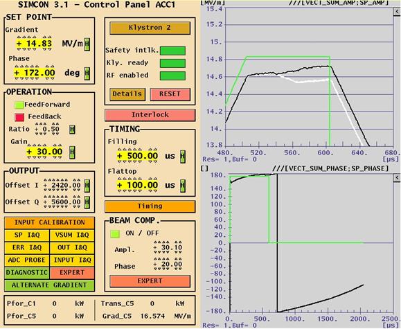
FLASH rf gun. beam generated within the (1.3 GHz) RF gun by a laser. filling time: typical 55 μs. flat top time: up to 800 μs
 RF gun by a laser. filling time: typical 55 μs. flat top time: up to 800 μs") The gun RF control at FLASH (and PITZ) Elmar Vogel in collaboration with Waldemar Koprek and Piotr Pucyk th FLASH Seminar at December 19 2006 FLASH rf gun beam generated within the (1.3 GHz) RF gun by
The gun RF control at FLASH (and PITZ) Elmar Vogel in collaboration with Waldemar Koprek and Piotr Pucyk th FLASH Seminar at December 19 2006 FLASH rf gun beam generated within the (1.3 GHz) RF gun by
Low-Level RF. S. Simrock, DESY. MAC mtg, May 05 Stefan Simrock DESY
 Low-Level RF S. Simrock, DESY Outline Scope of LLRF System Work Breakdown for XFEL LLRF Design for the VUV-FEL Cost, Personpower and Schedule RF Systems for XFEL RF Gun Injector 3rd harmonic cavity Main
Software Requirements Specification for LLRF Applications at FLASH Version 1.0 Prepared by Zheqiao Geng MSK, DESY Nov. 06, 2009
 Software Specification for LLRF Applications at FLASH Version 1.0 Prepared by Zheqiao Geng MSK, DESY Nov. 06, 2009 Copyright 2009 by Zheqiao Geng. Any change of this document should be agreed by the development
Cavity Field Control - RF Field Controller. LLRF Lecture Part3.3 S. Simrock, Z. Geng DESY, Hamburg, Germany
 Cavity Field Control - RF Field Controller LLRF Lecture Part3.3 S. Simrock, Z. Geng DESY, Hamburg, Germany Content Introduction to the controller Control scheme selection In-phase and Quadrature (I/Q)
Borut Baricevic. Libera LLRF. 17 September 2009
 Borut Baricevic Libera LLRF borut.baricevic@i-tech.si 17 September 2009 Outline Libera LLRF introduction Libera LLRF system topology Signal processing structure GUI and signal acquisition RF system diagnostics
Software Design Specification for LLRF Applications at FLASH Version 1.0 Prepared by Zheqiao Geng MSK, DESY Nov. 16, 2009
 Software Design Specification for LLRF Applications at FLASH Version 1.0 Prepared by Zheqiao Geng MSK, DESY Nov. 16, 2009 Copyright 2009 by Zheqiao Geng. Any change of this document should be agreed by
Functional block diagram for SIS8300. Christian Schmidt for the LLRF team Collaboration workshop
 Functional block diagram for SIS8300 Christian Schmidt for the LLRF team Collaboration workshop 2012 7.08.2012 Outline > Motivation and general comments > Preprocessing LLRF ADC board Block diagram Current
Superconducting cavity driving with FPGA controller
 TESLA-FEL 26-7 Superconducting cavity driving with FPGA controller Tomasz Czarski, Waldemar Koprek, Krzysztof T. Poźniak, Ryszard S. Romaniuk, Warsaw University of Technology Stefan Simrock, Alexander
MIMO-LTI Feedback Controller Design -Status report-
 MIMO-LTI Feedback Controller Design -Status report- Christian Schmidt Deutsches Elektronen Synchrotron Technische Universitaet Hamburg Harburg FLASH Seminar 4/1/28 Outline Current RF Feedback System MIMO
HOM Based Diagnostics at the TTF
 HOM Based Diagnostics at the TTF Nov 14, 2005 Josef Frisch, Nicoleta Baboi, Linda Hendrickson, Olaf Hensler, Douglas McCormick, Justin May, Olivier Napoly, Rita Paparella, Marc Ross, Claire Simon, Tonee
SNS LLRF Design Experience and its Possible Adoption for the ILC
 SNS LLRF Design Experience and its Possible Adoption for the ILC Brian Chase SNS - Mark Champion Fermilab International Linear Collider Workshop 11/28/2005 1 Why Consider the SNS System for ILC R&D at
Digital Self Excited Loop Implementation and Experience. Trent Allison Curt Hovater John Musson Tomasz Plawski
 Digital Self Excited Loop Implementation and Experience Trent Allison Curt Hovater John Musson Tomasz Plawski Overview Why Self Excited Loop? Algorithm Building Blocks Hardware and Sampling Digital Signal
Beam Diagnostics, Low Level RF and Feedback for Room Temperature FELs. Josef Frisch Pohang, March 14, 2011
 Beam Diagnostics, Low Level RF and Feedback for Room Temperature FELs Josef Frisch Pohang, March 14, 2011 Room Temperature / Superconducting Very different pulse structures RT: single bunch or short bursts
State of the Art in RF Control
 State of the Art in RF Control S. Simrock, DESY LINAC 2004, Lübeck Stefan Simrock DESY Outline RF System Architecture Requirements for RF Control RF Control Design Considerations Design Efforts Worldwide
Design and performance of LLRF system for CSNS/RCS *
 Design and performance of LLRF system for CSNS/RCS * LI Xiao 1) SUN Hong LONG Wei ZHAO Fa-Cheng ZHANG Chun-Lin Institute of High Energy Physics, Chinese Academy of Sciences, Beijing 100049, China Abstract:
COMPLEX ENVELOPE CONTROL OF PULSED ACCELERATING FIELD
 Tomasz Czarski COMPLEX ENVELOPE CONTROL OF PULSED ACCELERATING FIELD IN SUPERCONDUCTING CAVITY RESONATORS L = 9 λ/2 ~ 1037 particle (z,τ) E 0 (z) 0 z Institute of Electronic Systems Publishing House of
INTRA-TRAIN LONGITUDINAL FEEDBACK FOR BEAM STABILIZATION AT FLASH
 INTRA-TRAIN LONGITUDINAL FEEDBACK FOR BEAM STABILIZATION AT FLASH W. Koprek*, C. Behrens, M. K. Bock, M. Felber, P. Gessler, K. Hacker, H. Schlarb, C. Schmidt, B. Steffen, S. Wesch, DESY, Hamburg, Germany
Laboratory Report INFN Milano LASA
 Laboratory Report INFN Milano LASA Activities Underway Wire Position Monitor: new generation WPMs mounted on cryomodule and readout connected to control system Piezo Vibration Control: microphonic control
Review on Progress in RF Control Systems. Cornell University. Matthias Liepe. M. Liepe, Cornell U. SRF 2005, July 14
 Review on Progress in RF Control Systems Matthias Liepe Cornell University 1 Why this Talk? As we all know, superconducting cavities have many nice features one of which is very high field stability. Why?
Digital Logic, Algorithms, and Functions for the CEBAF Upgrade LLRF System Hai Dong, Curt Hovater, John Musson, and Tomasz Plawski
 Digital Logic, Algorithms, and Functions for the CEBAF Upgrade LLRF System Hai Dong, Curt Hovater, John Musson, and Tomasz Plawski Introduction: The CEBAF upgrade Low Level Radio Frequency (LLRF) control
LLRF Plans for SMTF. Ruben Carcagno (Fermilab) Nigel Lockyer (University of Pennsylvania) Thanks to DESY, PISA, KEK, Fermilab, SLAC Colleagues
 Nigel Lockyer (University of Pennsylvania) Thanks to DESY, PISA, KEK, Fermilab, SLAC Colleagues") LLRF Plans for SMTF Ruben Carcagno (Fermilab) Nigel Lockyer (University of Pennsylvania) Thanks to DESY, PISA, KEK, Fermilab, SLAC Colleagues Outline Near-term (< 1.5 years) SMTF LLRF plan Long-term (>
LLRF Plans for SMTF Ruben Carcagno (Fermilab) Nigel Lockyer (University of Pennsylvania) Thanks to DESY, PISA, KEK, Fermilab, SLAC Colleagues Outline Near-term (< 1.5 years) SMTF LLRF plan Long-term (>
Performance Evaluation of the Upgraded BAMs at FLASH
 Performance Evaluation of the Upgraded BAMs at FLASH with a compact overview of the BAM, the interfacing systems & a short outlook for 2019. Marie K. Czwalinna On behalf of the Special Diagnostics team
Digital LLRF Test on the Renascence Cryomodule
 Digital LLRF Test on the Renascence Cryomodule Trent Allison, Rama Bachimanchi, Curt Hovater, John Musson and Tomasz Plawski Introduction The Renascence cryomodule was the first opportunity for testing
Performance of the Prototype NLC RF Phase and Timing Distribution System *
 SLAC PUB 8458 June 2000 Performance of the Prototype NLC RF Phase and Timing Distribution System * Josef Frisch, David G. Brown, Eugene Cisneros Stanford Linear Accelerator Center, Stanford University,
A True Differential Millimeter Wave System with Port Power Control. Presented by: Suren Singh
 A True Differential Millimeter Wave System with Port Power Control Presented by: Suren Singh Agenda Need for True Differential and RF Power Control Vector Network Analyzer RF Port Power Control Port Power
Linac Coherent Light Source (LCLS) Low Level RF Status LCLS FAC. October 30, 2007
 Low Level RF Status LCLS FAC. October 30, 2007") Linac Coherent Light Source (LCLS) Low Level RF Status LCLS Emma LCLS RF Gun, L0, and L1 Emma Dual Feed L0A L0B L0A 57MV 19MV/m L0B 72MV 24MV/m Off Axis Injector Vault Injector Transverse Accelerator 55cm
Linac Coherent Light Source (LCLS) Low Level RF Status LCLS Emma LCLS RF Gun, L0, and L1 Emma Dual Feed L0A L0B L0A 57MV 19MV/m L0B 72MV 24MV/m Off Axis Injector Vault Injector Transverse Accelerator 55cm
FPGA-BASED PULSED-RF PHASE AND AMPLITUDE DETECTOR AT SLRI
 doi:10.18429/jacow-icalepcs2017- FPGA-BASED PULSED-RF PHASE AND AMPLITUDE DETECTOR AT SLRI R. Rujanakraikarn, Synchrotron Light Research Institute, Nakhon Ratchasima, Thailand Abstract In this paper, the
- RF Master-Reference Update (F.Ludwig, H.Weddig - DESY, K.Czuba - TU Warsaw) - Beam Stability Update (C.Gerth, F.Ludwig, G.
 - Beam Stability Update (C.Gerth, F.Ludwig, G.") FLASH Meeting, 21/04/09 Beam Stability at FLASH - update F.Ludwig - DESY Content : - Motivation - RF Master-Reference Update (F.Ludwig, H.Weddig - DESY, K.Czuba - TU Warsaw) - Beam Stability Update (C.Gerth,
FLASH Meeting, 21/04/09 Beam Stability at FLASH - update F.Ludwig - DESY Content : - Motivation - RF Master-Reference Update (F.Ludwig, H.Weddig - DESY, K.Czuba - TU Warsaw) - Beam Stability Update (C.Gerth,
RF Locking of Femtosecond Lasers
 RF Locking of Femtosecond Lasers Josef Frisch, Karl Gumerlock, Justin May, Steve Smith SLAC Work supported by DOE contract DE-AC02-76SF00515 1 Overview FEIS 2013 talk discussed general laser locking concepts
DEVELOPMENT OF A DLLRF USING COMERCIAL UTCA PLATFORM
 ACDIV-2017-11 May 2017 DEVELOPMENT OF A DLLRF USING COMERCIAL UTCA PLATFORM A. Salom, E. Morales, F. Pérez - ALBA Synchrotron Abstract The Digital LLRF of ALBA has been implemented using commercial cpci
RF-based Synchronization of the Seed and Pump-Probe Lasers to the Optical Synchronization System at FLASH
 RF-based Synchronization of the Seed and Pump-Probe Lasers to the Optical Synchronization System at FLASH Introduction to the otical synchronization system and concept of RF generation for locking of Ti:Sapphire
LLRF Operation and Performance of the European XFEL. An overview
 LLRF Operation and Performance of the European XFEL. An overview Mathieu Omet LLRF, Barcelona, 16.10.2017 Contents > Introduction > LLRF commissioning > Energy Reach > LLRF performance > Summary / Outlook
Digital Signal Processing in RF Applications
 Digital Signal Processing in RF Applications Part II Thomas Schilcher Outline 1. signal conditioning / down conversion 2. detection of amp./phase by digital I/Q sampling I/Q sampling non I/Q sampling digital
Reconfigurable 6 GHz RF Vector Signal Transceiver with 1 GHz Bandwidth
 CALIBRATION PROCEDURE PXIe-5840 Reconfigurable 6 GHz RF Vector Signal Transceiver with 1 GHz Bandwidth This document contains the verification procedures for the PXIe-5840 vector signal transceiver. Refer
EUROFEL-Report-2006-DS EUROPEAN FEL Design Study
 EUROFEL-Report-2006-DS3-034 EUROPEAN FEL Design Study Deliverable N : D 3.8 Deliverable Title: RF Amplitude and Phase Detector Task: Author: DS-3 F.Ludwig, M.Hoffmann, M.Felber, Contract N : 011935 P.Strzalkowski,
Added Phase Noise measurement for EMBRACE LO distribution system
 Added Phase Noise measurement for EMBRACE LO distribution system G. Bianchi 1, S. Mariotti 1, J. Morawietz 2 1 INAF-IRA (I), 2 ASTRON (NL) 1. Introduction Embrace is a system composed by 150 receivers,
Amplitude and Phase Stability of Analog Components for the LLRF System of the PEFP Accelerator
 Journal of the Korean Physical Society, Vol. 52, No. 3, March 2008, pp. 766770 Amplitude and Phase Stability of Analog Components for the LLRF System of the PEFP Accelerator Kyung-Tae Seol, Hyeok-Jung
Supplemental Slides: MIMO Testbed Development at the MPRG Lab
 Supplemental Slides: MIMO Testbed Development at the MPRG Lab Raqibul Mostafa Jeffrey H. Reed Slide 1 Overview Space Time Coding (STC) Overview Virginia Tech Space Time Adaptive Radio (VT-STAR) description:
R.Bachimanchi, IPAC, May 2015, Richmond, VA
 1 new module C100 Cryomodule Seven cell Cavity, 0.7 m long (high Q L ) 8 Cavities per Cryomodule Fits the existing Cryomodule footprint Fundamental frequency f 0 Accelerating gradient E acc 1497 MHz >
Calibration Techniques for the Home Lab
 Calibration Techniques for the Home Lab Jacques Audet VE2AZX jacaudet@videotron.ca Web: ve2azx.net September 2018 ve2azx.net 1 Summary - Using a reference multimeter as a calibrator for less accurate instruments.
MASSACHUSETTS INSTITUTE OF TECHNOLOGY HAYSTACK OBSERVATORY WESTFORD, MASSACHUSETTS
 To: From: EDGES MEMO #104 MASSACHUSETTS INSTITUTE OF TECHNOLOGY HAYSTACK OBSERVATORY WESTFORD, MASSACHUSETTS 01886 January 14, 2013 Telephone: 781-981-5400 Fax: 781-981-0590 EDGES Group Alan E.E. Rogers
A Synchrotron Phase Detector for the Fermilab Booster
 FERMILAB-TM-2234 A Synchrotron Phase Detector for the Fermilab Booster Xi Yang and Rene Padilla Fermi National Accelerator Laboratory Box 5, Batavia IL 651 Abstract A synchrotron phase detector is diagnostic
ESS-Bilbao Contribution to ESS Warm LINAC High Power RF Systems
 ESS-Bilbao Contribution to ESS Warm LINAC High Power RF Systems Arash Kaftoosian RF Group www.essbilbao.org On behalf of: Pedro Gonzalez Ibon Bustinduy RF Project Leader MEBT Project Leader ESS-Bilbao
Spurious and Stability Analysis under Large-Signal Conditions using your Vector Network Analyser
 Spurious and Stability Analysis under Large-Signal Conditions using your Vector Network Analyser An application of ICE June 2012 Outline Why combining Large-Signal and Small-Signal Measurements Block Diagram
Pre-distortion. General Principles & Implementation in Xilinx FPGAs
 Pre-distortion General Principles & Implementation in Xilinx FPGAs Issues in Transmitter Design 3G systems place much greater requirements on linearity and efficiency of RF transmission stage Linearity
Figure 4.1 Vector representation of magnetic field.
 Chapter 4 Design of Vector Magnetic Field Sensor System 4.1 3-Dimensional Vector Field Representation The vector magnetic field is represented as a combination of three components along the Cartesian coordinate
C100 Cryomodule. Seven cell Cavity, 0.7 m long (high Q L ) 8 Cavities per Cryomodule Fits the existing Cryomodule footprint
 8 Cavities per Cryomodule Fits the existing Cryomodule footprint") 1 new module C100 Cryomodule Seven cell Cavity, 0.7 m long (high Q L ) 8 Cavities per Cryomodule Fits the existing Cryomodule footprint Fundamental frequency f 0 Accelerating gradient E acc 1497 MHz >
1 new module C100 Cryomodule Seven cell Cavity, 0.7 m long (high Q L ) 8 Cavities per Cryomodule Fits the existing Cryomodule footprint Fundamental frequency f 0 Accelerating gradient E acc 1497 MHz >
INSTALLATION AND FIRST COMMISSIONING OF THE LLRF SYSTEM
 INSTALLATION AND FIRST COMMISSIONING OF THE LLRF SYSTEM FOR THE EUROPEAN XFEL Julien Branlard, for the LLRF team TALK OVERVIEW 2 Introduction Brief reminder about the XFEL LLRF system Commissioning goals
10th ESLS RF Meeting September ALBA RF System. F. Perez. on behalf of the ALBA RF Group. ALBA RF System 1/21
 ALBA RF System F. Perez on behalf of the ALBA RF Group ALBA RF System 1/21 Synchrotron Light Source in Cerdanyola (Barcelona, Spain) 3 GeV accelerator 30 beamlines (7 on day one) 50-50 Spanish Government
W-band vector network analyzer based on an audio lock-in amplifier * Abstract
 SLAC PUB 7884 July 1998 W-band vector network analyzer based on an audio lock-in amplifier * R. H. Siemann Stanford Linear Accelerator Center, Stanford University, Stanford CA 94309 Abstract The design
Cavity Field Control - Feedback Performance and Stability Analysis. LLRF Lecture Part3.2 S. Simrock, Z. Geng DESY, Hamburg, Germany
 Cavity Field Control - Feedback Performance and Stability Analysis LLRF Lecture Part3.2 S. Simrock, Z. Geng DESY, Hamburg, Germany Motivation Understand how the perturbations and noises influence the feedback
Utilizzo del Time Domain per misure EMI
 Utilizzo del Time Domain per misure EMI Roberto Sacchi Measurement Expert Manager - Europe 7 Giugno 2017 Compliance EMI receiver requirements (CISPR 16-1-1 ) range 9 khz - 18 GHz: A normal +/- 2 db absolute
Predictions of LER-HER limits
 Predictions of LER-HER limits PEP-II High Current Performance T. Mastorides, C. Rivetta, J.D. Fox, D. Van Winkle Accelerator Technology Research Div., SLAC 2e 34 Meeting, May 2, 27 Contents In this presentation
Slide Title. Bulleted Text
 Slide Title 1 Slide Outline Title Brief view of the C-AD Complex Review of the RHIC LLRF Upgrade Platform Generic Implementation of a Feedback Loop RHIC Bunch by Bunch Longitudinal Damper Cavity Controller
New apparatus for precise synchronous phase shift measurements in storage rings 1
 New apparatus for precise synchronous phase shift measurements in storage rings 1 Boris Podobedov and Robert Siemann Stanford Linear Accelerator Center, Stanford University, Stanford, CA 94309 Measuring
RF System Models and Longitudinal Beam Dynamics
 RF System Models and Longitudinal Beam Dynamics T. Mastoridis 1, P. Baudrenghien 1, J. Molendijk 1, C. Rivetta 2, J.D. Fox 2 1 BE-RF Group, CERN 2 AARD-Feedback and Dynamics Group, SLAC T. Mastoridis LLRF
Keysight Technologies
 Keysight Technologies Generating Signals Basic CW signal Block diagram Applications Analog Modulation Types of analog modulation Block diagram Applications Digital Modulation Overview of IQ modulation
Development of the Model of a Self Excited Loop
 Development of the Model of a Self Excited Loop Introduction Development of model in digital domain RF Power System Limiter Controller Loop Phase Shifter Test Results Gopal Joshi, BARC Initial Experiments
Microphonics. T. Powers
 Microphonics T. Powers What is microphonics? Microphonics is the time domain variation in cavity frequency driven by external vibrational sources. A 1.5 GHz structure 0.5 m long will change in frequency
PROPAGATION CHANNEL EMULATOR : ECP
 PROPAGATION CHANNEL EMULATOR : ECP The ECP (Propagation Channel Emulator) synthesizes the principal phenomena of propagation occurring on RF signal links between earth and space. Developed by the R&D laboratory,
The Phased Array Feed Receiver System : Linearity, Cross coupling and Image Rejection
 The Phased Array Feed Receiver System : Linearity, Cross coupling and Image Rejection D. Anish Roshi 1,2, Robert Simon 1, Steve White 1, William Shillue 2, Richard J. Fisher 2 1 National Radio Astronomy
USE OF MATLAB IN SIGNAL PROCESSING LABORATORY EXPERIMENTS
 USE OF MATLAB SIGNAL PROCESSG LABORATORY EXPERIMENTS R. Marsalek, A. Prokes, J. Prokopec Institute of Radio Electronics, Brno University of Technology Abstract: This paper describes the use of the MATLAB
PUBLICATION. A Novel Approach for Automatic Control of Piezoelectric Elements Used for Lorentz Force Detuning Compensation
 EuCARD-CON-21-4 European Coordination for Accelerator Research and Development PUBLICATION A Novel Approach for Automatic Control of Piezoelectric Elements Used for Lorentz Force Detuning Compensation
Automatic phase calibration for RF cavities using beam-loading signals. Jonathan Edelen LLRF 2017 Workshop (Barcelona) 18 Oct 2017
 18 Oct 2017") Automatic phase calibration for RF cavities using beam-loading signals Jonathan Edelen LLRF 2017 Workshop (Barcelona) 18 Oct 2017 Introduction How do we meet 10-4 energy stability for PIP-II? 2 11/9/2017
Automatic phase calibration for RF cavities using beam-loading signals Jonathan Edelen LLRF 2017 Workshop (Barcelona) 18 Oct 2017 Introduction How do we meet 10-4 energy stability for PIP-II? 2 11/9/2017
A Modular Readout System For A Small Liquid Argon TPC Carl Bromberg, Dan Edmunds Michigan State University
 A Modular Readout System For A Small Liquid Argon TPC Carl Bromberg, Dan Edmunds Michigan State University Abstract A dual-fet preamplifier and a multi-channel waveform digitizer form the basis of a modular
Baseband simulation model of the vector rf voltage control system for the J-PARC RCS
 Journal of Physics: Conference Series PAPER OPEN ACCESS Baseband simulation model of the vector rf voltage control system for the J-PARC RCS To cite this article: Fumihiko Tamura et al 2018 J. Phys.: Conf.
Architecture and Performance of the PEP-II Low-Level RF System*
 Architecture and Performance of the PEP-II Low-Level System* P. Corredoura Stanford Linear Accelerator Center, Stanford, Ca 9439, USA Abstract Heavy beam loading in the PEP-II B Factory along with large
Power Amplifier Linearization using RF Pre-Distortion JUNE, 2012
 Power Amplifier Linearization using RF Pre-Distortion JUNE, 2012 1 PA Linearization Overview General principles Overview/Block Diagram of DPD and RFPD RFPAL System architecture & Implementation Predistortion
AM Stabilized RF Amplifier Driver
 LIGO T00074 AM Stabilized RF Amplifier Driver SURF Project Final Report August 00 Jing Luo Mentor: Daniel Sigg Co Mentor: Paul Schwinberg Abstract: The AOM/EOM driver is a high power RF amplifier used
Development of Control Algorithm for Ring Laser Gyroscope
 International Journal of Scientific and Research Publications, Volume 2, Issue 10, October 2012 1 Development of Control Algorithm for Ring Laser Gyroscope P. Shakira Begum, N. Neelima Department of Electronics
The CMS ECAL Laser Monitoring System
 The CMS ECAL Laser Monitoring System CALOR 2006 XII INTERNATIONAL CONFERENCE on CALORIMETRY in HIGH ENERGY PHYSICS Adi Bornheim California Institute of Technology Chicago, June 8, 2006 Introduction CMS
레이저의주파수안정화방법및그응용 박상언 ( 한국표준과학연구원, 길이시간센터 )
") 레이저의주파수안정화방법및그응용 박상언 ( 한국표준과학연구원, 길이시간센터 ) Contents Frequency references Frequency locking methods Basic principle of loop filter Example of lock box circuits Quantifying frequency stability Applications
레이저의주파수안정화방법및그응용 박상언 ( 한국표준과학연구원, 길이시간센터 ) Contents Frequency references Frequency locking methods Basic principle of loop filter Example of lock box circuits Quantifying frequency stability Applications
Chapter X Measuring VSWR and Gain in Wireless Systems By Eamon Nash
 Chapter X Measuring VSWR and Gain in Wireless Systems By Eamon Nash Introduction Measurement and control of gain and reflected power in wireless transmitters are critical auxiliary functions that are often
Data Sheet SC5317 & SC5318A. 6 GHz to 26.5 GHz RF Downconverter SignalCore, Inc. All Rights Reserved
 Data Sheet SC5317 & SC5318A 6 GHz to 26.5 GHz RF Downconverter www.signalcore.com 2018 SignalCore, Inc. All Rights Reserved Definition of Terms 1 Table of Contents 1. Definition of Terms... 2 2. Description...
Understanding RF and Microwave Analysis Basics
 Understanding RF and Microwave Analysis Basics Kimberly Cassacia Product Line Brand Manager Keysight Technologies Agenda µw Analysis Basics Page 2 RF Signal Analyzer Overview & Basic Settings Overview
Obtaining Flat Test Port Power with the Agilent 8360 s User Flatness Correction Feature. Product Note
 Obtaining Flat Test Port Power with the Agilent 8360 s User Flatness Correction Feature Product Note 8360-2 Introduction The 8360 series synthesized sweepers provide extremely flat power at your test port,
HP Archive. This vintage Hewlett Packard document was preserved and distributed by www. hparchive.com Please visit us on the web!
 HP Archive This vintage Hewlett Packard document was preserved and distributed by www. hparchive.com Please visit us on the web! On-line curator: Glenn Robb This document is for FREE distribution only!
Fast and Accurate RF component characterization enabled by FPGA technology
 Fast and Accurate RF component characterization enabled by FPGA technology Guillaume Pailloncy Senior Systems Engineer Agenda RF Application Challenges What are FPGAs and why are they useful? FPGA-based
LCLS-II LLRF Prototype Testing and Characterization. Larry Doolittle, Brian Chase, Joshua Einstein-Curtis, Carlos Serrano LLRF 17,
 LCLS-II LLRF Prototype Testing and Characterization Larry Doolittle, Brian Chase, Joshua Einstein-Curtis, Carlos Serrano LLRF 17, 2017-10-16 Outline A little background on LCLS-II LLRF Design - DSP algorithms
PC-OSCILLOSCOPE PCS500. Analog and digital circuit sections. Description of the operation
 PC-OSCILLOSCOPE PCS500 Analog and digital circuit sections Description of the operation Operation of the analog section This description concerns only channel 1 (CH1) input stages. The operation of CH2
Development of utca Hardware for BAM system at FLASH and XFEL
 Development of utca Hardware for BAM system at FLASH and XFEL Samer Bou Habib, Dominik Sikora Insitute of Electronic Systems Warsaw University of Technology Warsaw, Poland Jaroslaw Szewinski, Stefan Korolczuk
Trajectory Measurements in the DAΦNE Transfer Line using log Amplifier
 K K DAΦNE TECHNICAL NOTE INFN - LNF, Accelerator Division Frascati, April 6, 2004 Note: CD-14 Trajectory Measurements in the DAΦNE Transfer Line using log Amplifier A. Stella, O. Coiro Abstract The diagnostic
Digitally-Controlled RF Self- Interference Canceller for Full-Duplex Radios
 Digitally-Controlled RF Self- nterference Canceller for Full-Duplex Radios Joose Tamminen 1, Matias Turunen 1, Dani Korpi 1, Timo Huusari 2, Yang-Seok Choi 2, Shilpa Talwar 2, and Mikko Valkama 1 1 Dept.
Tutorial on RF (Receiver Fundamentals) Frank Ludwig DESY
 Frank Ludwig DESY") Frank Ludwig DESY Outline Introduction to Noise and Systems Front-Ends Components Receiver Structures Distortions and Reduction Techniques Motivation Field regulation and noise sources : Beam energy jitter
Frank Ludwig DESY Outline Introduction to Noise and Systems Front-Ends Components Receiver Structures Distortions and Reduction Techniques Motivation Field regulation and noise sources : Beam energy jitter
Measuring Non-linear Amplifiers
 Measuring Non-linear Amplifiers Transceiver Components & Measuring Techniques MM3 Jan Hvolgaard Mikkelsen Radio Frequency Integrated Systems and Circuits Division Aalborg University 27 Agenda Non-linear
PXIe Contents CALIBRATION PROCEDURE. Reconfigurable 6 GHz RF Vector Signal Transceiver with 200 MHz Bandwidth
 IBRATION PROCEDURE PXIe-5646 Reconfigurable 6 GHz Vector Signal Transceiver with 200 MHz Bandwidth This document contains the verification and adjustment procedures for the PXIe-5646 vector signal transceiver.
Phase Drift Budget Analysis for 12 GeV 1497 MHz LLRF System
 Phase Drift Budget Analysis for 12 GeV 1497 MHz LLRF System John Musson 28-Sept-7 Introduction The 12 GeV upgrade effort included the creation of LLRF Requirements, directed at achieving.4% gradient regulation,.5
An Iterative Learning Algorithm for Control of an Accelerator Based Free Electron Laser
 Proceedings of the 47th IEEE Conference on Decision and Control Cancun, Mexico, Dec. 9-, 8 WeB5.5 An Iterative Learning Algorithm for Control of an Accelerator Based Free Electron Laser S. Kichhoff, C.
CUSTOM INTEGRATED ASSEMBLIES
 17 CUSTOM INTEGRATED ASSEMBLIES CUSTOM INTEGRATED ASSEMBLIES Cougar offers full first-level integration capabilities, providing not just performance components but also full subsystem solutions to help
LOI Progress Report -- Summary of Experiment in January
 LOI Progress Report -- Summary of Experiment in January 2010 -- LOI-7 February 18, 2010 1. Introduction Following the previous experiments in October, 2009, a new method to improve the RF waveform distortions
Acceleration of High-Intensity Protons in the J-PARC Synchrotrons. KEK/J-PARC M. Yoshii
 Acceleration of High-Intensity Protons in the J-PARC Synchrotrons KEK/J-PARC M. Yoshii Introduction 1. J-PARC consists of 400 MeV Linac, 3 GeV Rapid Cycling Synchrotron (RCS) and 50 GeV Main synchrotron
Chapter IX Using Calibration and Temperature Compensation to improve RF Power Detector Accuracy By Carlos Calvo and Anthony Mazzei
 Chapter IX Using Calibration and Temperature Compensation to improve RF Power Detector Accuracy By Carlos Calvo and Anthony Mazzei Introduction Accurate RF power management is a critical issue in modern
Digital Low Level RF for SESAME
 Technical Sector Synchrotron-light for Experimental Science And Applications in the Middle East Subject : RF More specified area: Digital Low Level RF Date: 6/23/2010 Total Number of Pages: 11 Document
Feedback Requirements for SASE FELS. Henrik Loos, SLAC IPAC 2010, Kyoto, Japan
 Feedback Requirements for SASE FELS Henrik Loos, SLAC, Kyoto, Japan 1 1 Henrik Loos Outline Stability requirements for SASE FELs Diagnostics for beam parameters Transverse: Beam position monitors Longitudinal:
Feedback Loop Canceller Circuit
 Feedback Loop Canceller Circuit Bachelor Thesis Ahmad Bader Ibrahim Obeidat Supervised by Prof. Dr.-Ing. Klaus Solbach 17.11.2014 Outline: 1 Motivation 2 Circuit description 3 Tasks and objectives 4 Active
High Power Couplers for TTF - FEL
 High Power Couplers for TTF - FEL 1. Requirements for High Power Couplers on superconducting Cavities 2. Characteristics of pulsed couplers 3. Standing wave pattern in the coaxial coupler line 4. Advantages
DESCRIPTION OF THE OPERATION AND CALIBRATION OF THE MILLIMETER I/Q PHASE BRIDGE-INTERFEROMETER
 DESCRIPTION OF THE OPERATION AND CALIBRATION OF THE MILLIMETER I/Q PHASE BRIDGE-INTERFEROMETER Overview of Interferometer Operation The block diagram of the I/Q Phase Bridge-Interferometer is shown below
Beamforming measurements. Markus Loerner, Market Segment Manager RF & microwave component test
 Beamforming measurements Markus Loerner, Market Segment Manager RF & microwave component test Phased Arrays not a new concept Airborne ı Phased Array Radars: since the 60 s ı Beams are steerable electronically
Sub-ps (and sub-micrometer) developments at ELETTRA
 developments at ELETTRA") Sub-ps (and sub-micrometer) developments at ELETTRA Mario Ferianis SINCROTRONE TRIESTE, Italy The ELETTRA laboratory ELETTRA is a 3 rd generation synchrotron light source in Trieste (I) since 1993 up to
Sub-ps (and sub-micrometer) developments at ELETTRA Mario Ferianis SINCROTRONE TRIESTE, Italy The ELETTRA laboratory ELETTRA is a 3 rd generation synchrotron light source in Trieste (I) since 1993 up to
LINEAR IC APPLICATIONS
 1 B.Tech III Year I Semester (R09) Regular & Supplementary Examinations December/January 2013/14 1 (a) Why is R e in an emitter-coupled differential amplifier replaced by a constant current source? (b)