Borut Baricevic. Libera LLRF. 17 September 2009
|
|
|
- Gervais Gilmore
- 5 years ago
- Views:
Transcription

1 Borut Baricevic Libera LLRF 17 September 2009
2 Outline Libera LLRF introduction Libera LLRF system topology Signal processing structure GUI and signal acquisition RF system diagnostics RF system tuning Demonstration of Libera LLRF on site Beam loading measurements Further developments
3 Introduction LLRF system with 38 RF input channels up to 12 GHz (in a 19 2U chassis ) Built-in sophisticated RF system diagnostics Reliable interlock system and chassis health monitoring Cavity field stabilization and cavity tuning Built in RF calibration and temperature stabilization systems Phase and amplitude stability meets 4th generation light sources requirements Compatible with normal-conducting and super-conducting RF systems in pulsed and continuous wave operation modes
4 System Topology RF frontend acquisition modules: 9 RF input channels with frequency conversion (up to 12 GHz) 9x 16 bit ADCs (130 MS/s) Virtex 5 FPGA DDR2 RAM (up to 8 Gbits) Vector Modulation module: Virtex 5 FPGA DDR2 RAM (up to 8 Gbits) 2 RF output channels 2 additional RF input channels Timing module: Generates a low jitter local oscillator signal and the sampling clock. Computing ICB module: Provides additional computing power, connectivity and flexibility.
5 32 Cavities LLRF System Example 32 CAVITY PROBE SIGNALS KLYSTRON DRIVE CAVITY & WAVEGUIDE TUNERS PROBE SIGNALS CAVITY FORWARD AND REFLECTED SIGNALS 19 Rack (Stack of 3 LLRF units serving 1 RF plant (Nth)) Beam diagnostics signal inputs Piezo & steppermotor control unit pre-amplifier KLYSTRON N 16 FORWARD AND 16 REFLECTED POW. SIGNALS 16 FORWARD AND 16 REFLECTED POW. SIGNALS 64 STEPPERMOTOR CONTROLS (WAVEGUIDE TUNING) 32 PIEZO AND 32 STEPPERMOTOR CONTROLS (CAVITY TUNING).. 32 cavities..
6 Signal Processing FPGA block diagram: The powerful digital processing system, based on multiple FPGAs implements a low latency cavity field control loop. The vector sum signal is obtained as a particular linear combination of the probe signals, defined by the matrix rotation. A digital NCO set-point signal is used to calculate the error signal. The error signal is processed by the control algorithm and a drive signal is therefore generated. An additional NCO signal is used for FF drive and RF system diagnostics purposes.
7 Signal Acquisition The signals can be acquired in each section of the processing chains. Two different acquisitions are simultaneously supported: Circular buffer RAW samples (Data on Demand) Decimated stream (Slow Acquisition) Scope of the acquisitions: Signal monitoring purposes Input for LLRF specific algorithms instantiated at the ICB Computing Module level (RF system response analysis, RF system tuning, adaptive FF, pulse shaping, beam based vector-sum calibration...)

")
8 GUI Overview (FLASH ACC456)


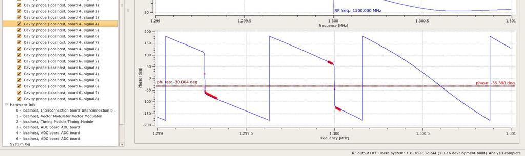
9 RF System Diagnostics RF System Response Characterization Sweep Analysis KLYSTRON Nyquist Stability Analysis Each cavity response is measured and analytically modeled by means of: Resonant frequency Loaded quality factor Amplitude and phase response at resonance RF system group delay The analytical models are passed to the Nyquist stability algorithm that automatically configures the phase rotation in order to maximize the stable region.

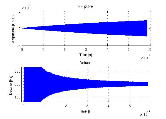
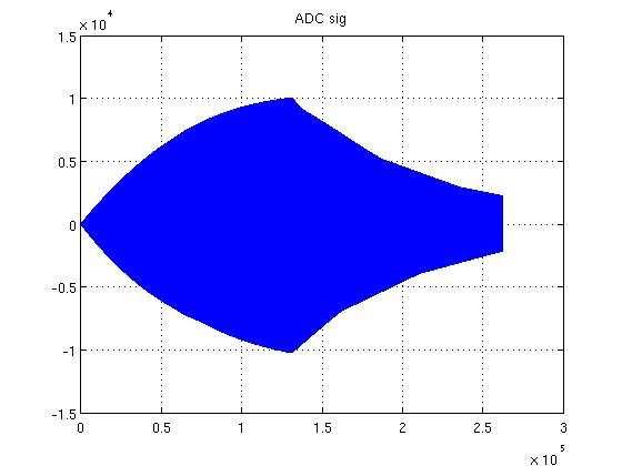
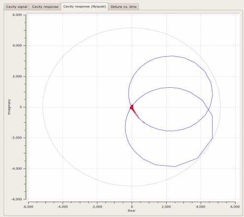
10 Advanced RF System Diagnostics RF System Response Characterization Upgrade for SC Cavities FLASH ACC4 Cavity 4
11 RF System Tuning The acquired data and the RF system diagnostics are integrated into the RF system tuning. In the specific case of the EMMA RF system 3 tuning loops involving independently the 19 cavities are implemented: - Phase control loops: Each pulse the flat top phase is measured and normalized with respect to the first cavity. The normalized phases are compared to the normalized zero crossing phase table and the difference is used to drive the phase shifter stepper motors. - Amplitude equalization loops: The amplitude of each pulse is normalized with respect to the first cavity. The difference from the ideal amplitude ratio is used to control the resonant frequency offset. - Cavity resonant frequency loops: The measured cavity resonant frequency is compared to the amplitude loop output. The difference is used to control the cavity plunger stepper motor. In the case of the first cavity a fixed offset is applied to the frequency control algorithm. IOT Drive A1-19 Փ1-19 foffs... Libera LLRF (Acquisition) Ac,1-19 Փc,1-19 fres,1-19 Libera LLRF (Tuning algorithm) Plunger Ph.shift
 Field stabilization: Amplitude: 0.005 % (5E-5) Phase: 0.")
 Also demonstrated: - RF system diagnostics - IOT power sweep - IOT frequency response -")
12 Demonstration at Daresbury High power tests on 2 EMMA NC 1.3 GHz cavities closed in a loop (April 2009) Field stabilization: Amplitude: % (5E-5) Phase: deg Peak power: 10 kw (1.6 ms; rep rate 10 Hz) Also demonstrated: - RF system diagnostics - IOT power sweep - IOT frequency response - Interlock system Additional requirements: - RF frequency variability (-1.5 MHz + 4 MHz) with Fixed MO frequency and synchronization with ALICE fixed RF ERL. - Tuning system
 Phase: 0.0095 deg Vector sum of 24 cavities Avg.")

13 Demonstration at DESY (FLASH) High power tests on the ACC SC 1.3 GHz cavities closed in a loop (July 2009) Field stabilization: Amplitude: % (9E-5) Phase: deg Vector sum of 24 cavities Avg. gradient: 10 MV/m Loop gain: 71 Also demonstrated: - Advanced RF system diagnostics - basic FF flexibility - passband modes diagnostics and suppression - Operation at 30 MV/m - Operation with beam loading - Operation of FLASH in SASE mode - Measurements of beam induced transients - Energy spread measurements after ACC456 - Beam based vector sum calibration Detailed report: _Flash_Tests_Summary.pdf
14 Beam Induced Transients Measurements (FLASH ACC456) Transients induced in ACC456 by 30, 1.2 nc bunches at the repetition rates of 250 khz and 1 MHz. The contribution of individual bunches can be distinguished on the global vector sum flat top.
Low-Level RF. S. Simrock, DESY. MAC mtg, May 05 Stefan Simrock DESY
 Low-Level RF S. Simrock, DESY Outline Scope of LLRF System Work Breakdown for XFEL LLRF Design for the VUV-FEL Cost, Personpower and Schedule RF Systems for XFEL RF Gun Injector 3rd harmonic cavity Main
SNS LLRF Design Experience and its Possible Adoption for the ILC
 SNS LLRF Design Experience and its Possible Adoption for the ILC Brian Chase SNS - Mark Champion Fermilab International Linear Collider Workshop 11/28/2005 1 Why Consider the SNS System for ILC R&D at
Software Requirements Specification for LLRF Applications at FLASH Version 1.0 Prepared by Zheqiao Geng MSK, DESY Nov. 06, 2009
 Software Specification for LLRF Applications at FLASH Version 1.0 Prepared by Zheqiao Geng MSK, DESY Nov. 06, 2009 Copyright 2009 by Zheqiao Geng. Any change of this document should be agreed by the development
Software Design Specification for LLRF Applications at FLASH Version 1.0 Prepared by Zheqiao Geng MSK, DESY Nov. 16, 2009
 Software Design Specification for LLRF Applications at FLASH Version 1.0 Prepared by Zheqiao Geng MSK, DESY Nov. 16, 2009 Copyright 2009 by Zheqiao Geng. Any change of this document should be agreed by
Cavity Field Control - RF Field Controller. LLRF Lecture Part3.3 S. Simrock, Z. Geng DESY, Hamburg, Germany
 Cavity Field Control - RF Field Controller LLRF Lecture Part3.3 S. Simrock, Z. Geng DESY, Hamburg, Germany Content Introduction to the controller Control scheme selection In-phase and Quadrature (I/Q)
FLASH rf gun. beam generated within the (1.3 GHz) RF gun by a laser. filling time: typical 55 μs. flat top time: up to 800 μs
 RF gun by a laser. filling time: typical 55 μs. flat top time: up to 800 μs") The gun RF control at FLASH (and PITZ) Elmar Vogel in collaboration with Waldemar Koprek and Piotr Pucyk th FLASH Seminar at December 19 2006 FLASH rf gun beam generated within the (1.3 GHz) RF gun by
The gun RF control at FLASH (and PITZ) Elmar Vogel in collaboration with Waldemar Koprek and Piotr Pucyk th FLASH Seminar at December 19 2006 FLASH rf gun beam generated within the (1.3 GHz) RF gun by
Review on Progress in RF Control Systems. Cornell University. Matthias Liepe. M. Liepe, Cornell U. SRF 2005, July 14
 Review on Progress in RF Control Systems Matthias Liepe Cornell University 1 Why this Talk? As we all know, superconducting cavities have many nice features one of which is very high field stability. Why?
INSTALLATION AND FIRST COMMISSIONING OF THE LLRF SYSTEM
 INSTALLATION AND FIRST COMMISSIONING OF THE LLRF SYSTEM FOR THE EUROPEAN XFEL Julien Branlard, for the LLRF team TALK OVERVIEW 2 Introduction Brief reminder about the XFEL LLRF system Commissioning goals
Functional block diagram for SIS8300. Christian Schmidt for the LLRF team Collaboration workshop
 Functional block diagram for SIS8300 Christian Schmidt for the LLRF team Collaboration workshop 2012 7.08.2012 Outline > Motivation and general comments > Preprocessing LLRF ADC board Block diagram Current
State of the Art in RF Control
 State of the Art in RF Control S. Simrock, DESY LINAC 2004, Lübeck Stefan Simrock DESY Outline RF System Architecture Requirements for RF Control RF Control Design Considerations Design Efforts Worldwide
Digital LLRF Test on the Renascence Cryomodule
 Digital LLRF Test on the Renascence Cryomodule Trent Allison, Rama Bachimanchi, Curt Hovater, John Musson and Tomasz Plawski Introduction The Renascence cryomodule was the first opportunity for testing
Microphonics. T. Powers
 Microphonics T. Powers What is microphonics? Microphonics is the time domain variation in cavity frequency driven by external vibrational sources. A 1.5 GHz structure 0.5 m long will change in frequency
LLRF Plans for SMTF. Ruben Carcagno (Fermilab) Nigel Lockyer (University of Pennsylvania) Thanks to DESY, PISA, KEK, Fermilab, SLAC Colleagues
 Nigel Lockyer (University of Pennsylvania) Thanks to DESY, PISA, KEK, Fermilab, SLAC Colleagues") LLRF Plans for SMTF Ruben Carcagno (Fermilab) Nigel Lockyer (University of Pennsylvania) Thanks to DESY, PISA, KEK, Fermilab, SLAC Colleagues Outline Near-term (< 1.5 years) SMTF LLRF plan Long-term (>
LLRF Plans for SMTF Ruben Carcagno (Fermilab) Nigel Lockyer (University of Pennsylvania) Thanks to DESY, PISA, KEK, Fermilab, SLAC Colleagues Outline Near-term (< 1.5 years) SMTF LLRF plan Long-term (>
Performance of the TTF Photoinjector Laser System
 Performance of the TTF Photoinjector Laser System S. Schreiber, DESY Laser Issues for Electron Photoinjectors, October 23-25, 22, Stanford, California, USA & I. Will, A. Liero, W. Sandner, MBI Berlin Overview
Beam Diagnostics, Low Level RF and Feedback for Room Temperature FELs. Josef Frisch Pohang, March 14, 2011
 Beam Diagnostics, Low Level RF and Feedback for Room Temperature FELs Josef Frisch Pohang, March 14, 2011 Room Temperature / Superconducting Very different pulse structures RT: single bunch or short bursts
EUROFEL-Report-2006-DS EUROPEAN FEL Design Study
 EUROFEL-Report-2006-DS3-034 EUROPEAN FEL Design Study Deliverable N : D 3.8 Deliverable Title: RF Amplitude and Phase Detector Task: Author: DS-3 F.Ludwig, M.Hoffmann, M.Felber, Contract N : 011935 P.Strzalkowski,
LLRF Operation and Performance of the European XFEL. An overview
 LLRF Operation and Performance of the European XFEL. An overview Mathieu Omet LLRF, Barcelona, 16.10.2017 Contents > Introduction > LLRF commissioning > Energy Reach > LLRF performance > Summary / Outlook
MIMO-LTI Feedback Controller Design -Status report-
 MIMO-LTI Feedback Controller Design -Status report- Christian Schmidt Deutsches Elektronen Synchrotron Technische Universitaet Hamburg Harburg FLASH Seminar 4/1/28 Outline Current RF Feedback System MIMO
C100 Cryomodule. Seven cell Cavity, 0.7 m long (high Q L ) 8 Cavities per Cryomodule Fits the existing Cryomodule footprint
 8 Cavities per Cryomodule Fits the existing Cryomodule footprint") 1 new module C100 Cryomodule Seven cell Cavity, 0.7 m long (high Q L ) 8 Cavities per Cryomodule Fits the existing Cryomodule footprint Fundamental frequency f 0 Accelerating gradient E acc 1497 MHz >
1 new module C100 Cryomodule Seven cell Cavity, 0.7 m long (high Q L ) 8 Cavities per Cryomodule Fits the existing Cryomodule footprint Fundamental frequency f 0 Accelerating gradient E acc 1497 MHz >
R.Bachimanchi, IPAC, May 2015, Richmond, VA
 1 new module C100 Cryomodule Seven cell Cavity, 0.7 m long (high Q L ) 8 Cavities per Cryomodule Fits the existing Cryomodule footprint Fundamental frequency f 0 Accelerating gradient E acc 1497 MHz >
Digital Self Excited Loop Implementation and Experience. Trent Allison Curt Hovater John Musson Tomasz Plawski
 Digital Self Excited Loop Implementation and Experience Trent Allison Curt Hovater John Musson Tomasz Plawski Overview Why Self Excited Loop? Algorithm Building Blocks Hardware and Sampling Digital Signal
Performance Evaluation of the Upgraded BAMs at FLASH
 Performance Evaluation of the Upgraded BAMs at FLASH with a compact overview of the BAM, the interfacing systems & a short outlook for 2019. Marie K. Czwalinna On behalf of the Special Diagnostics team
Digital Signal Processing in RF Applications
 Digital Signal Processing in RF Applications Part II Thomas Schilcher Outline 1. signal conditioning / down conversion 2. detection of amp./phase by digital I/Q sampling I/Q sampling non I/Q sampling digital
ALICE SRF SYSTEM COMMISSIONING EXPERIENCE A. Wheelhouse ASTeC, STFC Daresbury Laboratory
 ALICE SRF SYSTEM COMMISSIONING EXPERIENCE A. Wheelhouse ASTeC, STFC Daresbury Laboratory ERL 09 8 th 12 th June 2009 ALICE Accelerators and Lasers In Combined Experiments Brief Description ALICE Superconducting
- RF Master-Reference Update (F.Ludwig, H.Weddig - DESY, K.Czuba - TU Warsaw) - Beam Stability Update (C.Gerth, F.Ludwig, G.
 - Beam Stability Update (C.Gerth, F.Ludwig, G.") FLASH Meeting, 21/04/09 Beam Stability at FLASH - update F.Ludwig - DESY Content : - Motivation - RF Master-Reference Update (F.Ludwig, H.Weddig - DESY, K.Czuba - TU Warsaw) - Beam Stability Update (C.Gerth,
FLASH Meeting, 21/04/09 Beam Stability at FLASH - update F.Ludwig - DESY Content : - Motivation - RF Master-Reference Update (F.Ludwig, H.Weddig - DESY, K.Czuba - TU Warsaw) - Beam Stability Update (C.Gerth,
Calibrating the Cavity Voltage. Presentation of an idea
 Calibrating the Cavity Voltage. Presentation of an idea Stefan Wilke, DESY MHF-e 21st ESLS rf meeting Kraków, 15th/16th nov 2017 Accelerators at DESY. linear and circular Page 2 Accelerators at DESY. linear
Low Level RF Systems
 Low Level RF Systems Tom Powers Jan. 2015 (Slides stolen from: Powers LLRF workshop 2011, Plawski LLRF workshop 2013, Power/Hovater LBL light source working group 2012, Powers, HOM workshop 2012. LLRF
utca for SPS 200MHz Low Level RF Upgrade
 12th xtca Interest Group Meeting P. Baudrenghien, J. Galindo*, G. Hagmann, G. Kotzian, L. Schmid, A. Spierer CERN BE-RF Today s presentation -LOW LEVEL RF -CERN LLRF PLATFORMS -utca @ CERN-BE -PROOF OF
DEVELOPMENT OF A DLLRF USING COMERCIAL UTCA PLATFORM
 ACDIV-2017-11 May 2017 DEVELOPMENT OF A DLLRF USING COMERCIAL UTCA PLATFORM A. Salom, E. Morales, F. Pérez - ALBA Synchrotron Abstract The Digital LLRF of ALBA has been implemented using commercial cpci
COMPLEX ENVELOPE CONTROL OF PULSED ACCELERATING FIELD
 Tomasz Czarski COMPLEX ENVELOPE CONTROL OF PULSED ACCELERATING FIELD IN SUPERCONDUCTING CAVITY RESONATORS L = 9 λ/2 ~ 1037 particle (z,τ) E 0 (z) 0 z Institute of Electronic Systems Publishing House of
ABSTRACT 1 CEBAF UPGRADE CAVITY/CRYOMODULE
 Energy Content (Normalized) SC Cavity Resonance Control System for the 12 GeV Upgrade Cavity: Requirements and Performance T. Plawski, T. Allison, R. Bachimanchi, D. Hardy, C. Hovater, Thomas Jefferson
Electro-optic Spectral Decoding Measurements at FLASH
 Electro-optic Spectral Decoding Measurements at FLASH, FLA Florian Loehl, Sebastian Schulz, Laurens Wißmann Motivation Development of a robust online bunch length monitor for FLASH and XFEL Transition
Acceleration of High-Intensity Protons in the J-PARC Synchrotrons. KEK/J-PARC M. Yoshii
 Acceleration of High-Intensity Protons in the J-PARC Synchrotrons KEK/J-PARC M. Yoshii Introduction 1. J-PARC consists of 400 MeV Linac, 3 GeV Rapid Cycling Synchrotron (RCS) and 50 GeV Main synchrotron
RF-based Synchronization of the Seed and Pump-Probe Lasers to the Optical Synchronization System at FLASH
 RF-based Synchronization of the Seed and Pump-Probe Lasers to the Optical Synchronization System at FLASH Introduction to the otical synchronization system and concept of RF generation for locking of Ti:Sapphire
Design and performance of LLRF system for CSNS/RCS *
 Design and performance of LLRF system for CSNS/RCS * LI Xiao 1) SUN Hong LONG Wei ZHAO Fa-Cheng ZHANG Chun-Lin Institute of High Energy Physics, Chinese Academy of Sciences, Beijing 100049, China Abstract:
Improvements of the LLRF system at FLASH. Mariusz Grecki, Waldemar Koprek and LLRF team
 Improvements of the LLRF system at FLASH Mariusz Grecki, Waldemar Koprek and LLRF team Agenda GUN linearization Adaptive feed-forward at ACC1 Beam load compensation at ACC1 Klystron nonlinearity compensation
Physics Requirements Document Document Title: SCRF 1.3 GHz Cryomodule Document Number: LCLSII-4.1-PR-0146-R0 Page 1 of 7
 Document Number: LCLSII-4.1-PR-0146-R0 Page 1 of 7 Document Approval: Originator: Tor Raubenheimer, Physics Support Lead Date Approved Approver: Marc Ross, Cryogenic System Manager Approver: Jose Chan,
Slide Title. Bulleted Text
 Slide Title 1 Slide Outline Title Brief view of the C-AD Complex Review of the RHIC LLRF Upgrade Platform Generic Implementation of a Feedback Loop RHIC Bunch by Bunch Longitudinal Damper Cavity Controller
10th ESLS RF Meeting September ALBA RF System. F. Perez. on behalf of the ALBA RF Group. ALBA RF System 1/21
 ALBA RF System F. Perez on behalf of the ALBA RF Group ALBA RF System 1/21 Synchrotron Light Source in Cerdanyola (Barcelona, Spain) 3 GeV accelerator 30 beamlines (7 on day one) 50-50 Spanish Government
FLASH at DESY. FLASH. Free-Electron Laser in Hamburg. The first soft X-ray FEL operating two undulator beamlines simultaneously
 FLASH at DESY The first soft X-ray FEL operating two undulator beamlines simultaneously Katja Honkavaara, DESY for the FLASH team FEL Conference 2014, Basel 25-29 August, 2014 First Lasing FLASH2 > First
Cavity Field Control - Feedback Performance and Stability Analysis. LLRF Lecture Part3.2 S. Simrock, Z. Geng DESY, Hamburg, Germany
 Cavity Field Control - Feedback Performance and Stability Analysis LLRF Lecture Part3.2 S. Simrock, Z. Geng DESY, Hamburg, Germany Motivation Understand how the perturbations and noises influence the feedback
RF Locking of Femtosecond Lasers
 RF Locking of Femtosecond Lasers Josef Frisch, Karl Gumerlock, Justin May, Steve Smith SLAC Work supported by DOE contract DE-AC02-76SF00515 1 Overview FEIS 2013 talk discussed general laser locking concepts
Design & Implementation of the LLRF System for LCLS-II. Andy Benwell (SLAC Spokesperson) LLRF 2017 October 16, 2017
 LLRF 2017 October 16, 2017") Design & Implementation of the LLRF System for LCLS-II Andy Benwell (SLAC Spokesperson) LLRF 2017 October 16, 2017 Outline LCLS II LCLS II LLRF Requirements/Parameters LLRF Team LLRF Design Testing efforts
Design & Implementation of the LLRF System for LCLS-II Andy Benwell (SLAC Spokesperson) LLRF 2017 October 16, 2017 Outline LCLS II LCLS II LLRF Requirements/Parameters LLRF Team LLRF Design Testing efforts
EXPERIMENTAL RESULT OF LORENTZ DETUNING IN STF PHASE-1 AT KEK-STF
 EXPERIMENTAL RESULT OF LORENTZ DETUNING IN STF PHASE-1 AT KEK-STF Y. Yamamoto #, H. Hayano, E. Kako, T. Matsumoto, S. Michizono, T. Miura, S. Noguchi, M. Satoh, T. Shishidio, K. Watanabe, KEK, Tsukuba,
Development of utca Hardware for BAM system at FLASH and XFEL
 Development of utca Hardware for BAM system at FLASH and XFEL Samer Bou Habib, Dominik Sikora Insitute of Electronic Systems Warsaw University of Technology Warsaw, Poland Jaroslaw Szewinski, Stefan Korolczuk
Predictions of LER-HER limits
 Predictions of LER-HER limits PEP-II High Current Performance T. Mastorides, C. Rivetta, J.D. Fox, D. Van Winkle Accelerator Technology Research Div., SLAC 2e 34 Meeting, May 2, 27 Contents In this presentation
Feedback Requirements for SASE FELS. Henrik Loos, SLAC IPAC 2010, Kyoto, Japan
 Feedback Requirements for SASE FELS Henrik Loos, SLAC, Kyoto, Japan 1 1 Henrik Loos Outline Stability requirements for SASE FELs Diagnostics for beam parameters Transverse: Beam position monitors Longitudinal:
Advance on High Power Couplers for SC Accelerators
 Advance on High Power Couplers for SC Accelerators Eiji Kako (KEK, Japan) IAS conference at Hong Kong for High Energy Physics, 2017, January 23th Eiji KAKO (KEK, Japan) IAS at Hong Kong, 2017 Jan. 23 1
Status of superconducting module development suitable for cw operation: ELBE cryostats
 Status of superconducting module development suitable for cw operation: ELBE cryostats, A. Büchner, H. Büttig, F. Gabriel, P. Michel, K. Möller, U. Lehnert, Ch. Schneider, J. Stephan, A. Winter Forschungszentrum
Femtosecond Synchronization of Laser Systems for the LCLS
 Femtosecond Synchronization of Laser Systems for the LCLS, Lawrence Doolittle, Gang Huang, John W. Staples, Russell Wilcox (LBNL) John Arthur, Josef Frisch, William White (SLAC) 26 Aug 2010 FEL2010 1 Berkeley
Digital Low Level RF for SESAME
 Technical Sector Synchrotron-light for Experimental Science And Applications in the Middle East Subject : RF More specified area: Digital Low Level RF Date: 6/23/2010 Total Number of Pages: 11 Document
Time Matters How Power Meters Measure Fast Signals
 Time Matters How Power Meters Measure Fast Signals By Wolfgang Damm, Product Management Director, Wireless Telecom Group Power Measurements Modern wireless and cable transmission technologies, as well
Linac Coherent Light Source (LCLS) Low Level RF Status LCLS FAC. October 30, 2007
 Low Level RF Status LCLS FAC. October 30, 2007") Linac Coherent Light Source (LCLS) Low Level RF Status LCLS Emma LCLS RF Gun, L0, and L1 Emma Dual Feed L0A L0B L0A 57MV 19MV/m L0B 72MV 24MV/m Off Axis Injector Vault Injector Transverse Accelerator 55cm
Linac Coherent Light Source (LCLS) Low Level RF Status LCLS Emma LCLS RF Gun, L0, and L1 Emma Dual Feed L0A L0B L0A 57MV 19MV/m L0B 72MV 24MV/m Off Axis Injector Vault Injector Transverse Accelerator 55cm
FREIA Facility for Research Instrumentation and Accelerator Development Infrastructure and Control Architecture
 FREIA Facility for Research Instrumentation and Accelerator Development Infrastructure and Control Architecture Konrad Gajewski 10 September 2013, Uppsala Why FREIA? Several circumstances test stand for
Amplitude and Phase Stability of Analog Components for the LLRF System of the PEFP Accelerator
 Journal of the Korean Physical Society, Vol. 52, No. 3, March 2008, pp. 766770 Amplitude and Phase Stability of Analog Components for the LLRF System of the PEFP Accelerator Kyung-Tae Seol, Hyeok-Jung
Automatic phase calibration for RF cavities using beam-loading signals. Jonathan Edelen LLRF 2017 Workshop (Barcelona) 18 Oct 2017
 18 Oct 2017") Automatic phase calibration for RF cavities using beam-loading signals Jonathan Edelen LLRF 2017 Workshop (Barcelona) 18 Oct 2017 Introduction How do we meet 10-4 energy stability for PIP-II? 2 11/9/2017
Automatic phase calibration for RF cavities using beam-loading signals Jonathan Edelen LLRF 2017 Workshop (Barcelona) 18 Oct 2017 Introduction How do we meet 10-4 energy stability for PIP-II? 2 11/9/2017
Commissioning of the ALICE SRF Systems at Daresbury Laboratory Alan Wheelhouse, ASTeC, STFC Daresbury Laboratory ESLS RF 1 st 2 nd October 2008
 Commissioning of the ALICE SRF Systems at Daresbury Laboratory Alan Wheelhouse, ASTeC, STFC Daresbury Laboratory ESLS RF 1 st 2 nd October 2008 Overview ALICE (Accelerators and Lasers In Combined Experiments)
Direct Digital Down/Up Conversion for RF Control of Accelerating Cavities
 Direct Digital Down/Up Conversion for RF Control of Accelerating Cavities C. Hovater, T. Allison, R. Bachimanchi, J. Musson and T. Plawski Introduction As digital receiver technology has matured, direct
LCLS-II LLRF Prototype Testing and Characterization. Larry Doolittle, Brian Chase, Joshua Einstein-Curtis, Carlos Serrano LLRF 17,
 LCLS-II LLRF Prototype Testing and Characterization Larry Doolittle, Brian Chase, Joshua Einstein-Curtis, Carlos Serrano LLRF 17, 2017-10-16 Outline A little background on LCLS-II LLRF Design - DSP algorithms
MRI & NMR spectrometer
 AMOS MRI & NMR spectrometer The AMOS Spectrometer is a highly modular and flexible unit that provides the ability to customize synchronized configurations for preclinical and clinical MR applications.
Resonator System for the BEST 70MeV Cyclotron
 Resonator System for the BEST 70MeV Cyclotron 20 nd International Conference on Cyclotrons and their Applications Vancouver, Canada, September 16-20, 2013 Vasile Sabaiduc, Dipl. Eng. Accelerator Technology
Tuning systems for superconducting cavities at Saclay
 Tuning systems for superconducting cavities at Saclay 1 MACSE: 1990: tuner in LHe bath at 1.8K TTF: 1995 tuner at 1.8K in the insulating vacuum SOLEIL: 1999 tuner at 4 K in the insulating vacuum Super-3HC:
Models 296 and 295 combine sophisticated
 Established 1981 Advanced Test Equipment Rentals www.atecorp.com 800-404-ATEC (2832) Models 296 and 295 50 MS/s Synthesized Multichannel Arbitrary Waveform Generators Up to 4 Independent Channels 10 Standard
HIGH POWER PULSED TESTS OF A BETA=0.5 5-CELL 704 MHZ SUPERCONDUCTING CAVITY
 HIGH POWER PULSED TESTS OF A BETA=0.5 5-CELL 704 MHZ SUPERCONDUCTING CAVITY G. Devanz, D. Braud, M. Desmons, Y. Gasser, E. Jacques, O. Piquet, J. Plouin, J.- P. Poupeau, D. Roudier, P. Sahuquet, CEA-Saclay,
Synchronization Overview
 Synchronization Overview S. Simrock, DESY ERL Workshop 2005 Stefan Simrock DESY What is Synchronization Outline Synchronization Requirements for RF, Laser and Beam Timing stability RF amplitude and phase
taccor Optional features Overview Turn-key GHz femtosecond laser
 taccor Turn-key GHz femtosecond laser Self-locking and maintaining Stable and robust True hands off turn-key system Wavelength tunable Integrated pump laser Overview The taccor is a unique turn-key femtosecond
Digital Logic, Algorithms, and Functions for the CEBAF Upgrade LLRF System Hai Dong, Curt Hovater, John Musson, and Tomasz Plawski
 Digital Logic, Algorithms, and Functions for the CEBAF Upgrade LLRF System Hai Dong, Curt Hovater, John Musson, and Tomasz Plawski Introduction: The CEBAF upgrade Low Level Radio Frequency (LLRF) control
An Iterative Learning Algorithm for Control of an Accelerator Based Free Electron Laser
 Proceedings of the 47th IEEE Conference on Decision and Control Cancun, Mexico, Dec. 9-, 8 WeB5.5 An Iterative Learning Algorithm for Control of an Accelerator Based Free Electron Laser S. Kichhoff, C.
A Synchrotron Phase Detector for the Fermilab Booster
 FERMILAB-TM-2234 A Synchrotron Phase Detector for the Fermilab Booster Xi Yang and Rene Padilla Fermi National Accelerator Laboratory Box 5, Batavia IL 651 Abstract A synchrotron phase detector is diagnostic
SYNCHRONIZATION SYSTEMS FOR ERLS
 SYNCHRONIZATION SYSTEMS FOR ERLS Stefan Simrock, Frank Ludwig, Holger Schlarb DESY Notkestr. 85, 22603 Hamburg News, Germany Corresponding author: Stefan Simrock DESY Notkestr. 85 22603 Hamburg, Germany
Installation Progress of the Laser-based Synchronization System at FLASH.
 Installation Progress of the Laser-based Synchronization System at FLASH. Overview, Experiences, Performance and Outlook Sebastian Schulz 1,2 on behalf of the FLASH LbSyn Team 1 Institute of Experimental
Baseband simulation model of the vector rf voltage control system for the J-PARC RCS
 Journal of Physics: Conference Series PAPER OPEN ACCESS Baseband simulation model of the vector rf voltage control system for the J-PARC RCS To cite this article: Fumihiko Tamura et al 2018 J. Phys.: Conf.
THE ORION PHOTOINJECTOR: STATUS and RESULTS
 THE ORION PHOTOINJECTOR: STATUS and RESULTS Dennis T. Palmer SLAC / ARDB ICFA Sardinia 4 July 2002 1. Introduction 2. Beam Dynamics Simulations 3. Photoinjector 1. RF Gun 2. Solenoidal Magnet 3. Diagnostics
Fabry Perot Resonator (CA-1140)
") Fabry Perot Resonator (CA-1140) The open frame Fabry Perot kit CA-1140 was designed for demonstration and investigation of characteristics like resonance, free spectral range and finesse of a resonator.
Fabry Perot Resonator (CA-1140) The open frame Fabry Perot kit CA-1140 was designed for demonstration and investigation of characteristics like resonance, free spectral range and finesse of a resonator.
Software Design of Digital Receiver using FPGA
 Software Design of Digital Receiver using FPGA G.C.Kudale 1, Dr.B.G.Patil 2, K. Aurobindo 3 1PG Student, Department of Electronics Engineering, Walchand College of Engineering, Sangli, Maharashtra, 2Associate
FTMS Booster X1 High-performance data acquisition system for FT-ICR MS
 FTMS Booster X1 High-performance data acquisition system for FT-ICR MS What is FTMS Booster? The Spectroswiss FTMS Booster X1 is a high-performance data acquisition and analysis system based on state-of-the-art
C0da-r I&9 Commissioning Experience with the PEP-XI Low-Level RF System*
 Cdar 9733 I&9 Commissioning Experience with the PEPXI LowLevel RF System* # SLACPUB753 f May 1997 (A) P. Corredoura, S. Allison, R. Claus, W. Ross, L. Sapozhnikov, H. D. Schwarz, R. Tighe, C. Yee, C. Ziomek
Normal-conducting high-gradient rf systems
 Normal-conducting high-gradient rf systems Introduction Motivation for high gradient Order of 100 GeV/km Operational and state-of-the-art SwissFEL C-band linac: Just under 30 MV/m CLIC prototypes: Over
INTRA-TRAIN LONGITUDINAL FEEDBACK FOR BEAM STABILIZATION AT FLASH
 INTRA-TRAIN LONGITUDINAL FEEDBACK FOR BEAM STABILIZATION AT FLASH W. Koprek*, C. Behrens, M. K. Bock, M. Felber, P. Gessler, K. Hacker, H. Schlarb, C. Schmidt, B. Steffen, S. Wesch, DESY, Hamburg, Germany
Abstract. Keywords: Super conducting cavity control, signal conversion, FPGA, DSP, optics fibers, FPGA with optical I/O, free electron laser, FEL
 EU contract number RII3-CT-2003-506395 CARE Conf-04-046-SRF SRF FPGA and optical network based LLRF distributed control system for TESLA-XFEL Linear Accelerator Krzysztof T. Pozniak, Ryszard S. Romaniuk,
Dark Current Kicker Studies at FLASH
 Dark Current Kicker Studies at FLASH F. Obier, J. Wortmann, S. Schreiber, W. Decking, K. Flöttmann FLASH Seminar, DESY, 02 Feb 2010 History of the dark current kicker 2005 Vertical kicker was installed
ni.com The NI PXIe-5644R Vector Signal Transceiver World s First Software-Designed Instrument
 The NI PXIe-5644R Vector Signal Transceiver World s First Software-Designed Instrument Agenda Hardware Overview Tenets of a Software-Designed Instrument NI PXIe-5644R Software Example Modifications Available
HOM Based Diagnostics at the TTF
 HOM Based Diagnostics at the TTF Nov 14, 2005 Josef Frisch, Nicoleta Baboi, Linda Hendrickson, Olaf Hensler, Douglas McCormick, Justin May, Olivier Napoly, Rita Paparella, Marc Ross, Claire Simon, Tonee
Performance of the Prototype NLC RF Phase and Timing Distribution System *
 SLAC PUB 8458 June 2000 Performance of the Prototype NLC RF Phase and Timing Distribution System * Josef Frisch, David G. Brown, Eugene Cisneros Stanford Linear Accelerator Center, Stanford University,
Jørgen S. Nielsen Center for Storage Ring Facilities (ISA) Aarhus University Denmark. ESLS-RF 22 (8/ ), ASTRID2 RF system 1
 Aarhus University Denmark. ESLS-RF 22 (8/ ), ASTRID2 RF system 1") Jørgen S. Nielsen Center for Storage Ring Facilities (ISA) Aarhus University Denmark ESLS-RF 22 (8/11 2018), ASTRID2 RF system 1 ASTRID2 is the new synchrotron light source in Aarhus, Denmark, since 2013
Jørgen S. Nielsen Center for Storage Ring Facilities (ISA) Aarhus University Denmark ESLS-RF 22 (8/11 2018), ASTRID2 RF system 1 ASTRID2 is the new synchrotron light source in Aarhus, Denmark, since 2013
ESS-Bilbao Contribution to ESS Warm LINAC High Power RF Systems
 ESS-Bilbao Contribution to ESS Warm LINAC High Power RF Systems Arash Kaftoosian RF Group www.essbilbao.org On behalf of: Pedro Gonzalez Ibon Bustinduy RF Project Leader MEBT Project Leader ESS-Bilbao
3.9 GHz System (AH1) XFEL WP46
 XFEL WP46") 3.9 GHz System (AH1) XFEL WP46 14th European XFEL Machine Advisory Committee Meeting 02 May 2016 Paolo Pierini, INFN & DESY Elmar Vogel, DESY + INFN/DESY contributors PPT version 1 26/04/2016 Outline Status
3.9 GHz System (AH1) XFEL WP46 14th European XFEL Machine Advisory Committee Meeting 02 May 2016 Paolo Pierini, INFN & DESY Elmar Vogel, DESY + INFN/DESY contributors PPT version 1 26/04/2016 Outline Status
RF Design of Normal Conducting Deflecting Cavity
 RF Design of Normal Conducting Deflecting Cavity Valery Dolgashev (SLAC), Geoff Waldschmidt, Ali Nassiri (Argonne National Laboratory, Advanced Photon Source) 48th ICFA Advanced Beam Dynamics Workshop
FLASH. FLASH Training: RF Gun. FLASH: the first soft X-ray FEL operating two undulator beamlines simultaneously. Siegfried Schreiber, DESY
 FLASH Training: RF Gun FLASH: the first soft X-ray FEL operating two undulator beamlines simultaneously Siegfried Schreiber, DESY FLASH Training DESY 17-Mar-2017 FLASH1 RF Gun History RF Guns operated
LLRF4 Evaluation Board
 LLRF4 Evaluation Board USPAS Lab Reference Author: Dmitry Teytelman Revision: 1.1 June 11, 2009 Copyright Dimtel, Inc., 2009. All rights reserved. Dimtel, Inc. 2059 Camden Avenue, Suite 136 San Jose, CA
The low level radio frequency control system for DC-SRF. photo-injector at Peking University *
 The low level radio frequency control system for DC-SRF photo-injector at Peking University * WANG Fang( 王芳 ) 1) FENG Li-Wen( 冯立文 ) LIN Lin( 林林 ) HAO Jian-Kui( 郝建奎 ) Quan Sheng-Wen( 全胜文 ) ZHANG Bao-Cheng(
Design Implementation Description for the Digital Frequency Oscillator
 Appendix A Design Implementation Description for the Frequency Oscillator A.1 Input Front End The input data front end accepts either analog single ended or differential inputs (figure A-1). The input
A high resolution bunch arrival time monitor system for FLASH / XFEL
 A high resolution bunch arrival time monitor system for FLASH / XFEL K. Hacker, F. Löhl, F. Ludwig, K.H. Matthiesen, H. Schlarb, B. Schmidt, A. Winter October 24 th Principle of the arrival time detection
Design considerations for the RF phase reference distribution system for X-ray FEL and TESLA
 Design considerations for the RF phase reference distribution system for X-ray FEL and TESLA Krzysztof Czuba *a, Henning C. Weddig #b a Institute of Electronic Systems, Warsaw University of Technology,
PROPAGATION CHANNEL EMULATOR : ECP
 PROPAGATION CHANNEL EMULATOR : ECP The ECP (Propagation Channel Emulator) synthesizes the principal phenomena of propagation occurring on RF signal links between earth and space. Developed by the R&D laboratory,
FlexDDS-NG DUAL. Dual-Channel 400 MHz Agile Waveform Generator
 FlexDDS-NG DUAL Dual-Channel 400 MHz Agile Waveform Generator Excellent signal quality Rapid parameter changes Phase-continuous sweeps High speed analog modulation Wieserlabs UG www.wieserlabs.com FlexDDS-NG
ArbStudio Arbitrary Waveform Generators. Powerful, Versatile Waveform Creation
 ArbStudio Arbitrary Waveform Generators Powerful, Versatile Waveform Creation UNMATCHED WAVEFORM UNMATCHED WAVEFORM GENERATION GENERATION Key Features 125 MHz bandwidth 1 GS/s maximum sample rate Long
PUBLICATION. A Novel Approach for Automatic Control of Piezoelectric Elements Used for Lorentz Force Detuning Compensation
 EuCARD-CON-21-4 European Coordination for Accelerator Research and Development PUBLICATION A Novel Approach for Automatic Control of Piezoelectric Elements Used for Lorentz Force Detuning Compensation
PRODUCT AND CAPABILITY SUMMARY
 APPLIED SYSTEMS ENGINEERING, INC. PO BOX 122987 FORT WORTH, TEXAS 76121 TELEPHONE: (817) 249-4180 FAX: (817) 249-3413 PRODUCT AND CAPABILITY SUMMARY RADAR - PULSE, DUAL MODE, BOTH GRID PULSED AND CW AND
Digital Phase Control Techniques for Accelerator Cavities.
 Digital Phase Control Techniques for Accelerator Cavities. Amos Dexter, Imran Tahir, Graeme Burt and Richard Carter Lancaster University Engineering Department Abstract RF cavities used for the acceleration