- RF Master-Reference Update (F.Ludwig, H.Weddig - DESY, K.Czuba - TU Warsaw) - Beam Stability Update (C.Gerth, F.Ludwig, G.
|
|
|
- Laureen Shepherd
- 5 years ago
- Views:
Transcription
1 FLASH Meeting, 21/04/09 Beam Stability at FLASH - update F.Ludwig - DESY Content : - Motivation - RF Master-Reference Update (F.Ludwig, H.Weddig - DESY, K.Czuba - TU Warsaw) - Beam Stability Update (C.Gerth, F.Ludwig, G.Möller - DESY, C.Schmidt - TU Hamburg Harburg)
2 Motivation n Schematic Layout of FLASH : A cavity field fluctuation of 1% causes 6ps bunch arrival time: % required for 10fs (without feedbacks) F.Löhl, Optical Synchronization of a Free-Electron Laser with Femtosecond Precision, Hamburg 2009, Section 4.2 n Bunch arrival time stability with feedback : Reduce number of pilot bunches: - Setpoints near to proper values - Robust machine operation - Reduce ACC1 cavity fluctuations (short-term and long-term) - Stable RF-distribution system


 at Exp. Hall: 2deg drift /TTFelog/data/2008/30/25.07_a 1.3GHz vs.")
 at Exp. Hall: 2deg drift Inhouse PLL.")
3 RF-Master-Reference Update n Drift in Poseidon PLL Module : - 3 Degree! over 9 hours (3 DUT Lab measurement), 0.1deg typical! /TTFelog/data/2008/33/14.08_M timing drift between FEL(electrons) and PPLaser: 4ps drift, Streak /TTFelog/data/2008/33/13.08_M phase relation 1.3 GHz / 9 MHz pplaser TTFelog/data/2008/30/25.07_a 1.3GHz vs.108mhz (before new MO Installation) at Exp. Hall: 0.2 deg drift /TTFelog/data/2008/30/25.07_a 1.3GHz vs.108mhz (after new MO Installation) at Exp. Hall: 2deg drift /TTFelog/data/2008/30/25.07_a 1.3GHz vs. 9MHz (before new MO Installation) at Exp.Hall: 0.1 deg drift /TTFelog/data/2008/30/25.07_a 1.3GHz vs. 81MHz (after new MO Installation) at Exp. Hall: 2deg drift Inhouse PLL. n Streak Camera : Bunch arrival time ACC1 Setpoint changes +/-1ps,0.5deg,8 hours (peak-to-peak) ACC1 Setpoint changes Mainly caused from 1300MHz distribution cable (0.8ps (rms) using reflectometry methods) and ACC1 drifts.

4 RF-Master-Reference Update n Long-term stability comparison between Injector and Exp. Hall : 1.5ps 400fs 120fs Detected problems: - Phase detection is limited by 16-Bit ADCs and dividers - Phase jumps are caused by users - Upgrade FSB Box in Exp.Hall - Upgrade to 24-Bit ADCs - Replace dividers by multipliers (limited upconversion frequencies!) - Use driftfree phase detectors

5 RF-Master-Reference Update n Upgrade FSB module in Exp. Hall, because of cabling. Change to ½ cables
6 Robust machine operation n Proposal for a robust long-term stable machine operation : Beam-based Feedback Learning Feedforward Injection of a reference Reference Tracking - Short ACC1 ½ type pickup cables - Field detectors located at cavities - N-Type connectors -> PCBs
7 Beam Stability - Pulse-to-Pulse Fluctuations eg e.g. 2Device Under Test in FLASH / 06/2008 n ACC1 Noise watchdog : Energy jiter SR-PMT Monitor - Regulation system : ACC1 close loop Field detection ACC1 System Field detection DEV System - Regulation system: DEV open loop Should be zero infinite gain
8 Beam Stability - Pulse-to-Pulse Fluctuations %/ 2 Theoretical expectation 1/ 2 n ACC1 : % n DEV : % Actual limit is the field detector n SR-PMT : % 0088% (Energy jitter)


9 Field Detector Performance Tests at FLASH n FLASH field detector performance test using the reference : Ampltude and Phase

10 Field Detector Performance Tests at FLASH n FLASH field detector performance test using the reference : Limit determined by correlation measurement n Improvement of field detection? : No improvement ADC noise N parallel receiver limitation, channels MO O( (minor) o) (modular system, ATCA) 30fs -> 7fs 3x less noise


11 Field Detector Performance Tests at FLASH n Improve strange FPGA behaviour for Vsum scaling :
12 Field Detection Methods and Status 04/09 n Downconverter Noise and Drift Sources : - LO-Generation, ADC Noise, Receiver and FPGA IQ Detection - Cable drifts - Microphonics from Vector-Sum Calibration caused by non-linearity, cross-talk, field-flatness EUROFEL DS3.9, Delivery Report n Status of the Performance Evaluation ation : 01/2008 Section 1.5, F.Ludwig et.al % Confguration: 1: Passive Receiver, 16-bit ADC ACB 2.1, 2: Active Receiver, 14-bit ADC SIMCON 3.1 3: Active Receiver, 14-bit ADC FLASH Boards, 4: 12-bit ADC, 200Msps


 6:04h:")

")
")


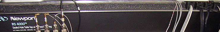
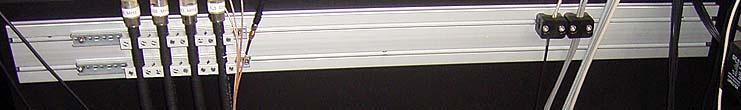
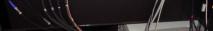
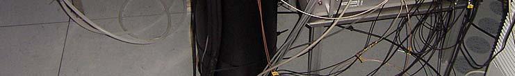
13 Beam Stability Mechanical Distortions - Cables Cable test in the injector, approx. 2mm motion!!! ACC1,DEV1 LFF ON, Gain=50, Pyro Feedback OFF Action: 6:01h: shot 130 DEV Injector door open (probe cable touch inner door) 6:02h: shot 200 DEV Probe cable bunch (Attenuator to DWC 1300MHz) 6:03h: shot 300 DEV IF cable bunch (baseband DWC to ADC) 6:04h: shot 400 DEV RF MO signal to VM 6:04h: shot 450 DEV Injector door close 6:05h: shot 700 ACC1 Probe cable bunch DWC input (sensitive,cause interlocks) 6:05h: shot 1200 ACC1 phase readjustment 6:11h: shot 1700 (approx) ACC1 Probe cable bunch 1/2" top rack, attenuator partly not fixed! 6:13h: shot 2500 New MO Main bunch distribution (right panel, middle rack 2) SASE: - Driftcalibration in phase and amplitude - Short ACC1 ½ type pickup cables - Field detectors located at cavities - N-Type connectors -> PCBs
14 Drift Calibration Schemes under Development Is needed to eliminate pulse-to-pulse fluctuations and drifts from - Cavity ypickup p cables (4 module) fs m K, ± 125fs K ( ± 25m), Δ T 1K - Downconverter (mixer) θ A = 2e-3/ C, θ P = 0.2 / C (Injector) - LO generation (dividers, amplifiers, filters) - ADC CLK generation (timing system, less critical) to have a robust machine operation. Cavity Flattop Beam pause t 1) Tracking the reference : 2) Injection of the reference signal : Calibration Line REF Reference Receivers,e.g.direct e ect sampling Receiver, e.g.non-iq-sampling ADC ADC REF ADC REF LO, CLK Gen CLK Gen + Demonstrated, e.g. with direct sampling + High symmetric receivers + Low amplitude drifts 3) Reflection at the cavity : + Compensates in addition antenna to cavity pickup
15 Cavity Field Flatness Learning Feedforward OFF ACC1 gain sweep [50, 2] SASE level instable
16 Cavity Field Flatness Learning Feedforward ON ACC1 gain sweep [50, 2] SASE level more stable
17 FLASH Meeting, 21/04/09 n Summary - Absolute phase noise of Master-Reference is improved. - Bunch arrival time is limited by 1300 cable and ACC1 drifts. - Phase detectors are limited for lower frequencies -> 24-Bit ADC, multipliers, driftfree detectors. - ACC1 field detectors are the main reason for the the short-term and long-term energy jitter. - A Learning feedforward makes SASE more stable. - A proposal for a robust machine operation for ACC1 is presented. n Outlook - Drift calibrated field detectors are needed. - ADC noise will be overcome by parallel receiver channels in a modular system. - Learning feedforward must be implemented into FLASH. - Driftfree phase detectors. - Exp. Hall FSB Upgrade. Special thanks to C.Schmidt, C.Gerth, G.Möller
18 Thanks for your attention!
19 Backup Slides
20 Choice of the Modulation Scheme n ADC equilvalent noise spectral density : /sqrt(hz)] tral Density [nv/ Nois se Voltage Spect AD7641 AD7760 AD9446 MAX19586 LTC2207 ADS5546 LTC2241 LTC2242 ADS5463 AD9230 LTC2208 AD e n = V FS,pp 8 10 SNR ( f 20, ε ) s ε 2 f A lot of available ADCs have roughtly the same performance. s sampling rate [Msps] Baseband I,Q Demodulation IF Sampling Direct Sampling
EUROFEL-Report-2006-DS EUROPEAN FEL Design Study
 EUROFEL-Report-2006-DS3-034 EUROPEAN FEL Design Study Deliverable N : D 3.8 Deliverable Title: RF Amplitude and Phase Detector Task: Author: DS-3 F.Ludwig, M.Hoffmann, M.Felber, Contract N : 011935 P.Strzalkowski,
Cavity Field Control - RF Field Controller. LLRF Lecture Part3.3 S. Simrock, Z. Geng DESY, Hamburg, Germany
 Cavity Field Control - RF Field Controller LLRF Lecture Part3.3 S. Simrock, Z. Geng DESY, Hamburg, Germany Content Introduction to the controller Control scheme selection In-phase and Quadrature (I/Q)
RF-based Synchronization of the Seed and Pump-Probe Lasers to the Optical Synchronization System at FLASH
 RF-based Synchronization of the Seed and Pump-Probe Lasers to the Optical Synchronization System at FLASH Introduction to the otical synchronization system and concept of RF generation for locking of Ti:Sapphire
Tutorial on RF (Receiver Fundamentals) Frank Ludwig DESY
 Frank Ludwig DESY") Frank Ludwig DESY Outline Introduction to Noise and Systems Front-Ends Components Receiver Structures Distortions and Reduction Techniques Motivation Field regulation and noise sources : Beam energy jitter
Frank Ludwig DESY Outline Introduction to Noise and Systems Front-Ends Components Receiver Structures Distortions and Reduction Techniques Motivation Field regulation and noise sources : Beam energy jitter
RF-Based Detector for Measuring Fiber Length Changes with Sub-5 Femtosecond Long-Term Stability.
 RF-Based Detector for Measuring Fiber Length Changes with Sub-5 Femtosecond Long-Term Stability. J. Zemella 1, V. Arsov 1, M. K. Bock 1, M. Felber 1, P. Gessler 1, K. Gürel 3, K. Hacker 1, F. Löhl 1, F.
Development of utca Hardware for BAM system at FLASH and XFEL
 Development of utca Hardware for BAM system at FLASH and XFEL Samer Bou Habib, Dominik Sikora Insitute of Electronic Systems Warsaw University of Technology Warsaw, Poland Jaroslaw Szewinski, Stefan Korolczuk
Borut Baricevic. Libera LLRF. 17 September 2009
 Borut Baricevic Libera LLRF borut.baricevic@i-tech.si 17 September 2009 Outline Libera LLRF introduction Libera LLRF system topology Signal processing structure GUI and signal acquisition RF system diagnostics
Low-Level RF. S. Simrock, DESY. MAC mtg, May 05 Stefan Simrock DESY
 Low-Level RF S. Simrock, DESY Outline Scope of LLRF System Work Breakdown for XFEL LLRF Design for the VUV-FEL Cost, Personpower and Schedule RF Systems for XFEL RF Gun Injector 3rd harmonic cavity Main
MIMO-LTI Feedback Controller Design -Status report-
 MIMO-LTI Feedback Controller Design -Status report- Christian Schmidt Deutsches Elektronen Synchrotron Technische Universitaet Hamburg Harburg FLASH Seminar 4/1/28 Outline Current RF Feedback System MIMO
FLASH rf gun. beam generated within the (1.3 GHz) RF gun by a laser. filling time: typical 55 μs. flat top time: up to 800 μs
 RF gun by a laser. filling time: typical 55 μs. flat top time: up to 800 μs") The gun RF control at FLASH (and PITZ) Elmar Vogel in collaboration with Waldemar Koprek and Piotr Pucyk th FLASH Seminar at December 19 2006 FLASH rf gun beam generated within the (1.3 GHz) RF gun by
The gun RF control at FLASH (and PITZ) Elmar Vogel in collaboration with Waldemar Koprek and Piotr Pucyk th FLASH Seminar at December 19 2006 FLASH rf gun beam generated within the (1.3 GHz) RF gun by
Femtosecond Synchronization of Laser Systems for the LCLS
 Femtosecond Synchronization of Laser Systems for the LCLS, Lawrence Doolittle, Gang Huang, John W. Staples, Russell Wilcox (LBNL) John Arthur, Josef Frisch, William White (SLAC) 26 Aug 2010 FEL2010 1 Berkeley
Electro-optic Spectral Decoding Measurements at FLASH
 Electro-optic Spectral Decoding Measurements at FLASH, FLA Florian Loehl, Sebastian Schulz, Laurens Wißmann Motivation Development of a robust online bunch length monitor for FLASH and XFEL Transition
Linac Coherent Light Source (LCLS) Low Level RF Status LCLS FAC. October 30, 2007
 Low Level RF Status LCLS FAC. October 30, 2007") Linac Coherent Light Source (LCLS) Low Level RF Status LCLS Emma LCLS RF Gun, L0, and L1 Emma Dual Feed L0A L0B L0A 57MV 19MV/m L0B 72MV 24MV/m Off Axis Injector Vault Injector Transverse Accelerator 55cm
Linac Coherent Light Source (LCLS) Low Level RF Status LCLS Emma LCLS RF Gun, L0, and L1 Emma Dual Feed L0A L0B L0A 57MV 19MV/m L0B 72MV 24MV/m Off Axis Injector Vault Injector Transverse Accelerator 55cm
INTRA-TRAIN LONGITUDINAL FEEDBACK FOR BEAM STABILIZATION AT FLASH
 INTRA-TRAIN LONGITUDINAL FEEDBACK FOR BEAM STABILIZATION AT FLASH W. Koprek*, C. Behrens, M. K. Bock, M. Felber, P. Gessler, K. Hacker, H. Schlarb, C. Schmidt, B. Steffen, S. Wesch, DESY, Hamburg, Germany
A high resolution bunch arrival time monitor system for FLASH / XFEL
 A high resolution bunch arrival time monitor system for FLASH / XFEL K. Hacker, F. Löhl, F. Ludwig, K.H. Matthiesen, H. Schlarb, B. Schmidt, A. Winter October 24 th Principle of the arrival time detection
Functional block diagram for SIS8300. Christian Schmidt for the LLRF team Collaboration workshop
 Functional block diagram for SIS8300 Christian Schmidt for the LLRF team Collaboration workshop 2012 7.08.2012 Outline > Motivation and general comments > Preprocessing LLRF ADC board Block diagram Current
Performance Evaluation of the Upgraded BAMs at FLASH
 Performance Evaluation of the Upgraded BAMs at FLASH with a compact overview of the BAM, the interfacing systems & a short outlook for 2019. Marie K. Czwalinna On behalf of the Special Diagnostics team
Installation Progress of the Laser-based Synchronization System at FLASH.
 Installation Progress of the Laser-based Synchronization System at FLASH. Overview, Experiences, Performance and Outlook Sebastian Schulz 1,2 on behalf of the FLASH LbSyn Team 1 Institute of Experimental
PLL Synchronizer User s Manual / Version 1.0.6
 PLL Synchronizer User s Manual / Version 1.0.6 AccTec B.V. Den Dolech 2 5612 AZ Eindhoven The Netherlands phone +31 (0) 40-2474321 / 4048 e-mail AccTecBV@tue.nl Contents 1 Introduction... 3 2 Technical
Feedback Requirements for SASE FELS. Henrik Loos, SLAC IPAC 2010, Kyoto, Japan
 Feedback Requirements for SASE FELS Henrik Loos, SLAC, Kyoto, Japan 1 1 Henrik Loos Outline Stability requirements for SASE FELs Diagnostics for beam parameters Transverse: Beam position monitors Longitudinal:
Status on Pulsed Timing Distribution Systems and Implementations at DESY, FERMI and XFEL
 FLS Meeting March 7, 2012 Status on Pulsed Timing Distribution Systems and Implementations at DESY, FERMI and XFEL Franz X. Kärtner Center for Free-Electron Laser Science, DESY and Department of Physics,
Synchronization Overview
 Synchronization Overview S. Simrock, DESY ERL Workshop 2005 Stefan Simrock DESY What is Synchronization Outline Synchronization Requirements for RF, Laser and Beam Timing stability RF amplitude and phase
synchronization system
 Status of the optical synchronization system Holger Schlarb DESY for the LbSyn team V. Arsov, M. C. Behrens, Bock, P. Gessler, M. Felber, K. Hacker, F. Loehl, F. Ludwig, K-H. Matthiesen, B. Schmidt, S.
Design considerations for the RF phase reference distribution system for X-ray FEL and TESLA
 Design considerations for the RF phase reference distribution system for X-ray FEL and TESLA Krzysztof Czuba *a, Henning C. Weddig #b a Institute of Electronic Systems, Warsaw University of Technology,
Performance of the Prototype NLC RF Phase and Timing Distribution System *
 SLAC PUB 8458 June 2000 Performance of the Prototype NLC RF Phase and Timing Distribution System * Josef Frisch, David G. Brown, Eugene Cisneros Stanford Linear Accelerator Center, Stanford University,
Beam Diagnostics, Low Level RF and Feedback for Room Temperature FELs. Josef Frisch Pohang, March 14, 2011
 Beam Diagnostics, Low Level RF and Feedback for Room Temperature FELs Josef Frisch Pohang, March 14, 2011 Room Temperature / Superconducting Very different pulse structures RT: single bunch or short bursts
Software Requirements Specification for LLRF Applications at FLASH Version 1.0 Prepared by Zheqiao Geng MSK, DESY Nov. 06, 2009
 Software Specification for LLRF Applications at FLASH Version 1.0 Prepared by Zheqiao Geng MSK, DESY Nov. 06, 2009 Copyright 2009 by Zheqiao Geng. Any change of this document should be agreed by the development
RF Locking of Femtosecond Lasers
 RF Locking of Femtosecond Lasers Josef Frisch, Karl Gumerlock, Justin May, Steve Smith SLAC Work supported by DOE contract DE-AC02-76SF00515 1 Overview FEIS 2013 talk discussed general laser locking concepts
SYNCHRONIZATION SYSTEMS FOR ERLS
 SYNCHRONIZATION SYSTEMS FOR ERLS Stefan Simrock, Frank Ludwig, Holger Schlarb DESY Notkestr. 85, 22603 Hamburg News, Germany Corresponding author: Stefan Simrock DESY Notkestr. 85 22603 Hamburg, Germany
Femtosecond-stability delivery of synchronized RFsignals to the klystron gallery over 1-km optical fibers
 FEL 2014 August 28, 2014 THB03 Femtosecond-stability delivery of synchronized RFsignals to the klystron gallery over 1-km optical fibers Kwangyun Jung 1, Jiseok Lim 1, Junho Shin 1, Heewon Yang 1, Heung-Sik
INSTALLATION AND FIRST COMMISSIONING OF THE LLRF SYSTEM
 INSTALLATION AND FIRST COMMISSIONING OF THE LLRF SYSTEM FOR THE EUROPEAN XFEL Julien Branlard, for the LLRF team TALK OVERVIEW 2 Introduction Brief reminder about the XFEL LLRF system Commissioning goals
FLASH at DESY. FLASH. Free-Electron Laser in Hamburg. The first soft X-ray FEL operating two undulator beamlines simultaneously
 FLASH at DESY The first soft X-ray FEL operating two undulator beamlines simultaneously Katja Honkavaara, DESY for the FLASH team FEL Conference 2014, Basel 25-29 August, 2014 First Lasing FLASH2 > First
LLRF Operation and Performance of the European XFEL. An overview
 LLRF Operation and Performance of the European XFEL. An overview Mathieu Omet LLRF, Barcelona, 16.10.2017 Contents > Introduction > LLRF commissioning > Energy Reach > LLRF performance > Summary / Outlook
Software Design Specification for LLRF Applications at FLASH Version 1.0 Prepared by Zheqiao Geng MSK, DESY Nov. 16, 2009
 Software Design Specification for LLRF Applications at FLASH Version 1.0 Prepared by Zheqiao Geng MSK, DESY Nov. 16, 2009 Copyright 2009 by Zheqiao Geng. Any change of this document should be agreed by
Added Phase Noise measurement for EMBRACE LO distribution system
 Added Phase Noise measurement for EMBRACE LO distribution system G. Bianchi 1, S. Mariotti 1, J. Morawietz 2 1 INAF-IRA (I), 2 ASTRON (NL) 1. Introduction Embrace is a system composed by 150 receivers,
FLASH performance after the upgrade. Josef Feldhaus
 FLASH performance after the upgrade Josef Feldhaus European XFEL / HASYLAB Users Meeting DESY, January 27, 2011 Upgrade 2009 / 2010 > Upgrade shutdown: September 2009 February 2010 exchanged RF stations
Ultrahigh precision synchronization of optical and microwave frequency sources
 Journal of Physics: Conference Series PAPER OPEN ACCESS Ultrahigh precision synchronization of optical and microwave frequency sources To cite this article: A Kalaydzhyan et al 2016 J. Phys.: Conf. Ser.
Spectral Phase Modulation and chirped pulse amplification in High Gain Harmonic Generation
 Spectral Phase Modulation and chirped pulse amplification in High Gain Harmonic Generation Z. Wu, H. Loos, Y. Shen, B. Sheehy, E. D. Johnson, S. Krinsky, J. B. Murphy, T. Shaftan,, X.-J. Wang, L. H. Yu,
Design Considerations for Phase Reference Distribution
 Design Considerations for Reference Distribution Rihua Zeng, Anders J Johansson September 13, 2012 Abstract Coaxial cable based solution and optical fibre based solution are discussed in this note for
Jitter Measurements using Phase Noise Techniques
 Jitter Measurements using Phase Noise Techniques Agenda Jitter Review Time-Domain and Frequency-Domain Jitter Measurements Phase Noise Concept and Measurement Techniques Deriving Random and Deterministic
Paul Scherrer Institute Pierre-André Duperrex. On-line calibration schemes for RF-based beam diagnostics
 Paul Scherrer Institute Pierre-André Duperrex On-line calibration schemes for RF-based beam diagnostics HB2012 Beijing, 17-20 Sept. 2012 Motivation Current monitor Some difficulties related to RF signal
Berkeley Nucleonics Corporation
 Berkeley Nucleonics Corporation A trusted source for quality and innovative instrumentation since 1963 Test And Measurement Nuclear Expertise RF/Microwave BNC at Our Core BNC Mission: Providing our customers
ADI 2006 RF Seminar. Chapter II RF/IF Components and Specifications for Receivers
 ADI 2006 RF Seminar Chapter II RF/IF Components and Specifications for Receivers 1 RF/IF Components and Specifications for Receivers Fixed Gain and Variable Gain Amplifiers IQ Demodulators Analog-to-Digital
BEAM ARRIVAL TIME MONITORS
 BEAM ARRIVAL TIME MONITORS J. Frisch SLAC National Accelerator Laboratory, Stanford CA 94305, USA Abstract We provide an overview of beam arrival time measurement techniques for FELs and other accelerators
Cavity Field Control - Feedback Performance and Stability Analysis. LLRF Lecture Part3.2 S. Simrock, Z. Geng DESY, Hamburg, Germany
 Cavity Field Control - Feedback Performance and Stability Analysis LLRF Lecture Part3.2 S. Simrock, Z. Geng DESY, Hamburg, Germany Motivation Understand how the perturbations and noises influence the feedback
Field Stability Issue for Normal Conducting Cavity under Beam Loading
 Field Stability Issue for Normal Conducting Cavity under Beam Loading Rihua Zeng, 3- - Introduction There is cavity field blip at the beginning of beam loading (~several ten micro-seconds) under PI control
Timing Noise Measurement of High-Repetition-Rate Optical Pulses
 564 Timing Noise Measurement of High-Repetition-Rate Optical Pulses Hidemi Tsuchida National Institute of Advanced Industrial Science and Technology 1-1-1 Umezono, Tsukuba, 305-8568 JAPAN Tel: 81-29-861-5342;
Performance of the TTF Photoinjector Laser System
 Performance of the TTF Photoinjector Laser System S. Schreiber, DESY Laser Issues for Electron Photoinjectors, October 23-25, 22, Stanford, California, USA & I. Will, A. Liero, W. Sandner, MBI Berlin Overview
Electro-Optical Measurements at the Swiss Light Source (SLS) Linac at the PSI. First Results
 Linac at the PSI. First Results") Electro-Optical Measurements at the Swiss Light Source (SLS) Linac at the PSI First Results Overview motivation electro-optical sampling general remarks experimental setup synchronisation between TiSa-laser
Electro-Optical Measurements at the Swiss Light Source (SLS) Linac at the PSI First Results Overview motivation electro-optical sampling general remarks experimental setup synchronisation between TiSa-laser
Automatic phase calibration for RF cavities using beam-loading signals. Jonathan Edelen LLRF 2017 Workshop (Barcelona) 18 Oct 2017
 18 Oct 2017") Automatic phase calibration for RF cavities using beam-loading signals Jonathan Edelen LLRF 2017 Workshop (Barcelona) 18 Oct 2017 Introduction How do we meet 10-4 energy stability for PIP-II? 2 11/9/2017
Automatic phase calibration for RF cavities using beam-loading signals Jonathan Edelen LLRF 2017 Workshop (Barcelona) 18 Oct 2017 Introduction How do we meet 10-4 energy stability for PIP-II? 2 11/9/2017
Amplitude and Phase Stability of Analog Components for the LLRF System of the PEFP Accelerator
 Journal of the Korean Physical Society, Vol. 52, No. 3, March 2008, pp. 766770 Amplitude and Phase Stability of Analog Components for the LLRF System of the PEFP Accelerator Kyung-Tae Seol, Hyeok-Jung
Testing with Femtosecond Pulses
 Testing with Femtosecond Pulses White Paper PN 200-0200-00 Revision 1.3 January 2009 Calmar Laser, Inc www.calmarlaser.com Overview Calmar s femtosecond laser sources are passively mode-locked fiber lasers.
Design and Evaluation of a Low-Level RF Control System Analog/Digital Receiver for the ILC Main LINACs
 FERMILAB-PUB-08-157-AD Design and Evaluation of a Low-Level RF Control System Analog/Digital Receiver for the ILC Main LINACs Keywords: ILC Main LINACs, LLRF, Digital Receiver, Vector Sum, high frequency
Infrared Single Shot Diagnostics for the Longitudinal. Profile of the Electron Bunches at FLASH. Disputation
 Infrared Single Shot Diagnostics for the Longitudinal Profile of the Electron Bunches at FLASH Disputation Hossein Delsim-Hashemi Tuesday 22 July 2008 7/23/2008 2/ 35 Introduction m eb c 2 3 2 γ ω = +
Review on Progress in RF Control Systems. Cornell University. Matthias Liepe. M. Liepe, Cornell U. SRF 2005, July 14
 Review on Progress in RF Control Systems Matthias Liepe Cornell University 1 Why this Talk? As we all know, superconducting cavities have many nice features one of which is very high field stability. Why?
Beam Arrival Time Monitors. Josef Frisch, IBIC Sept. 15, 2015
 Beam Arrival Time Monitors Josef Frisch, IBIC Sept. 15, 2015 Arrival Time Monitors Timing is only meaningful relative to some reference, and in general what matters is the relative timing of two different
Performance of the Reference and Timing Systems at SPring-8
 Performance of the Reference and Timing Systems at SPring-8 Outline Yuji Ohashi SPring-8 1. Introduction 2. Tools 3. Performances 4. New synchronization scheme between 508 and 2856 MHz 5. Summary Y.Kawashima
Phase Drift Budget Analysis for 12 GeV 1497 MHz LLRF System
 Phase Drift Budget Analysis for 12 GeV 1497 MHz LLRF System John Musson 28-Sept-7 Introduction The 12 GeV upgrade effort included the creation of LLRF Requirements, directed at achieving.4% gradient regulation,.5
utca for SPS 200MHz Low Level RF Upgrade
 12th xtca Interest Group Meeting P. Baudrenghien, J. Galindo*, G. Hagmann, G. Kotzian, L. Schmid, A. Spierer CERN BE-RF Today s presentation -LOW LEVEL RF -CERN LLRF PLATFORMS -utca @ CERN-BE -PROOF OF
Lock-Ins for electrical measurements
 Lock-Ins for electrical measurements At low temperatures small electrical signals, small signal changes interesting physics Problems: Noise Groundloops SNR FAM-Talk October 17 th 2014 1 Types of noise
Type Ordering Code Package TDA Q67000-A5168 P-DIP-18-5
 Video Modulator for FM-Audio TDA 5666-5 Preliminary Data Bipolar IC Features FM-audio modulator Sync level clamping of video input signal Controlling of peak white value Continuous adjustment of modulation
FLASH II. FLASH II: a second undulator line and future test bed for FEL development.
 FLASH II FLASH II: a second undulator line and future test bed for FEL development Bart.Faatz@desy.de Outline Proposal Background Parameters Layout Chalenges Timeline Cost estimate Personnel requirements
State of the Art in RF Control
 State of the Art in RF Control S. Simrock, DESY LINAC 2004, Lübeck Stefan Simrock DESY Outline RF System Architecture Requirements for RF Control RF Control Design Considerations Design Efforts Worldwide
Reconfigurable 6 GHz Vector Signal Transceiver with I/Q Interface
 SPECIFICATIONS PXIe-5645 Reconfigurable 6 GHz Vector Signal Transceiver with I/Q Interface Contents Definitions...2 Conditions... 3 Frequency...4 Frequency Settling Time... 4 Internal Frequency Reference...
Bunch-by-Bunch Broadband Feedback for the ESRF
 Bunch-by-Bunch Broadband Feedback for the ESRF ESLS RF meeting / Aarhus 21-09-2005 J. Jacob, E. Plouviez, J.-M. Koch, G. Naylor, V. Serrière Goal: Active damping of longitudinal and transverse multibunch
Improving Amplitude Accuracy with Next-Generation Signal Generators
 Improving Amplitude Accuracy with Next-Generation Signal Generators Generate True Performance Signal generators offer precise and highly stable test signals for a variety of components and systems test
Progress of the TEO experiment at FLASH
 Progress of the TEO experiment at VUV-FEL at DESY - Armin Azima S. Duesterer, J. Feldhaus, H. Schlarb, H. Redlin, B. Steffen, DESY Hamburg K. Sengstock, Uni Hamburg Adrian Cavalieri, David Fritz, David
PCS-150 / PCI-200 High Speed Boxcar Modules
 Becker & Hickl GmbH Kolonnenstr. 29 10829 Berlin Tel. 030 / 787 56 32 Fax. 030 / 787 57 34 email: info@becker-hickl.de http://www.becker-hickl.de PCSAPP.DOC PCS-150 / PCI-200 High Speed Boxcar Modules
레이저의주파수안정화방법및그응용 박상언 ( 한국표준과학연구원, 길이시간센터 )
") 레이저의주파수안정화방법및그응용 박상언 ( 한국표준과학연구원, 길이시간센터 ) Contents Frequency references Frequency locking methods Basic principle of loop filter Example of lock box circuits Quantifying frequency stability Applications
레이저의주파수안정화방법및그응용 박상언 ( 한국표준과학연구원, 길이시간센터 ) Contents Frequency references Frequency locking methods Basic principle of loop filter Example of lock box circuits Quantifying frequency stability Applications
Keysight Technologies
 Keysight Technologies Generating Signals Basic CW signal Block diagram Applications Analog Modulation Types of analog modulation Block diagram Applications Digital Modulation Overview of IQ modulation
HIGH-PRECISION LASER MASTER OSCILLATORS FOR OPTICAL TIMING DISTRIBUTION SYSTEMS IN FUTURE LIGHT SOURCES
 HIGH-PRECISION LASER MASTER OSCILLATORS FOR OPTICAL TIMING DISTRIBUTION SYSTEMS IN FUTURE LIGHT SOURCES Axel Winter, Peter Schmüser, Universität Hamburg, Hamburg, Germany, Frank Ludwig, Holger Schlarb,
MGM 3000X Q67000-A5179 P-DSO-20-1 (SMD) MGM 3000X Q67006-A5179 P-DSO-20-1 Tape & Reel (SMD)
 MGM 3000X Q67006-A5179 P-DSO-20-1 Tape & Reel (SMD)") Video Modulator for FM/AM-Audio MGM 3000X Bipolar IC Features FM- and AM-audio modulator Audio carrier output for suppression of harmonics Sync level clamping of video input signal Controlling of peak
Video Modulator for FM/AM-Audio MGM 3000X Bipolar IC Features FM- and AM-audio modulator Audio carrier output for suppression of harmonics Sync level clamping of video input signal Controlling of peak
Reconfigurable 6 GHz RF Vector Signal Transceiver with 1 GHz Bandwidth
 CALIBRATION PROCEDURE PXIe-5840 Reconfigurable 6 GHz RF Vector Signal Transceiver with 1 GHz Bandwidth This document contains the verification procedures for the PXIe-5840 vector signal transceiver. Refer
LNS ultra low phase noise Synthesizer 8 MHz to 18 GHz
 LNS ultra low phase noise Synthesizer 8 MHz to 18 GHz Datasheet The LNS is an easy to use 18 GHz synthesizer that exhibits outstanding phase noise and jitter performance in a 3U rack mountable chassis.
Improvements of the LLRF system at FLASH. Mariusz Grecki, Waldemar Koprek and LLRF team
 Improvements of the LLRF system at FLASH Mariusz Grecki, Waldemar Koprek and LLRF team Agenda GUN linearization Adaptive feed-forward at ACC1 Beam load compensation at ACC1 Klystron nonlinearity compensation
Demo / Application Guide for DSA815(-TG) / DSA1000 Series
 / DSA1000 Series") Demo / Application Guide for DSA815(-TG) / DSA1000 Series TX1000 Mobile Phone Frontend Mixer Bandpass Filter PA The schematic above shows a typical front end of a mobile phone. Our TX1000 RF Demo Kit shows
Demo / Application Guide for DSA815(-TG) / DSA1000 Series TX1000 Mobile Phone Frontend Mixer Bandpass Filter PA The schematic above shows a typical front end of a mobile phone. Our TX1000 RF Demo Kit shows
A TECHNIQUE TO EVALUATE THE IMPACT OF FLEX CABLE PHASE INSTABILITY ON mm-wave PLANAR NEAR-FIELD MEASUREMENT ACCURACIES
 A TECHNIQUE TO EVALUATE THE IMPACT OF FLEX CABLE PHASE INSTABILITY ON mm-wave PLANAR NEAR-FIELD MEASUREMENT ACCURACIES Daniël Janse van Rensburg Nearfield Systems Inc., 133 E, 223rd Street, Bldg. 524,
Narrow Pulse Measurements on Vector Network Analyzers
 Narrow Pulse Measurements on Vector Network Analyzers Bert Schluper Nearfield Systems Inc. Torrance, CA, USA bschluper@nearfield.com Abstract - This paper investigates practical aspects of measuring antennas
TIMING DISTRIBUTION AND SYNCHRONIZATION COMPLETE SOLUTIONS FROM ONE SINGLE SOURCE
 TIMING DISTRIBUTION AND SYNCHRONIZATION COMPLETE SOLUTIONS FROM ONE SINGLE SOURCE link stabilization FEMTOSECOND SYNCHRONIZATION FOR LARGE-SCALE FACILITIES TAILOR-MADE FULLY INTEGRATED SOLUTIONS The Timing
DEVELOPMENT OF A DLLRF USING COMERCIAL UTCA PLATFORM
 ACDIV-2017-11 May 2017 DEVELOPMENT OF A DLLRF USING COMERCIAL UTCA PLATFORM A. Salom, E. Morales, F. Pérez - ALBA Synchrotron Abstract The Digital LLRF of ALBA has been implemented using commercial cpci
THE ORION PHOTOINJECTOR: STATUS and RESULTS
 THE ORION PHOTOINJECTOR: STATUS and RESULTS Dennis T. Palmer SLAC / ARDB ICFA Sardinia 4 July 2002 1. Introduction 2. Beam Dynamics Simulations 3. Photoinjector 1. RF Gun 2. Solenoidal Magnet 3. Diagnostics
LCLS-II LLRF Prototype Testing and Characterization. Larry Doolittle, Brian Chase, Joshua Einstein-Curtis, Carlos Serrano LLRF 17,
 LCLS-II LLRF Prototype Testing and Characterization Larry Doolittle, Brian Chase, Joshua Einstein-Curtis, Carlos Serrano LLRF 17, 2017-10-16 Outline A little background on LCLS-II LLRF Design - DSP algorithms
Designing for Femtosecond Pulses
 Designing for Femtosecond Pulses White Paper PN 200-1100-00 Revision 1.1 July 2013 Calmar Laser, Inc www.calmarlaser.com Overview Calmar s femtosecond laser sources are passively mode-locked fiber lasers.
Utilizzo del Time Domain per misure EMI
 Utilizzo del Time Domain per misure EMI Roberto Sacchi Measurement Expert Manager - Europe 7 Giugno 2017 Compliance EMI receiver requirements (CISPR 16-1-1 ) range 9 khz - 18 GHz: A normal +/- 2 db absolute
Vidyut: Exploiting Power Line Infrastructure for Enterprise Wireless Networks. Vivek Yenamandra and Kannan Srinivasan
 Vidyut: Exploiting Power Line Infrastructure for Enterprise Wireless Networks Vivek Yenamandra and Kannan Srinivasan Motivation Increasing demand for wireless capacity Proliferation of BYOD in workplaces
LLRF Plans for SMTF. Ruben Carcagno (Fermilab) Nigel Lockyer (University of Pennsylvania) Thanks to DESY, PISA, KEK, Fermilab, SLAC Colleagues
 Nigel Lockyer (University of Pennsylvania) Thanks to DESY, PISA, KEK, Fermilab, SLAC Colleagues") LLRF Plans for SMTF Ruben Carcagno (Fermilab) Nigel Lockyer (University of Pennsylvania) Thanks to DESY, PISA, KEK, Fermilab, SLAC Colleagues Outline Near-term (< 1.5 years) SMTF LLRF plan Long-term (>
LLRF Plans for SMTF Ruben Carcagno (Fermilab) Nigel Lockyer (University of Pennsylvania) Thanks to DESY, PISA, KEK, Fermilab, SLAC Colleagues Outline Near-term (< 1.5 years) SMTF LLRF plan Long-term (>
FLASH: Status and upgrade
 : Status and upgrade The User Facility Layout Performance and operational o a issues Upgrade Bart Faatz for the team DESY FEL 2009 Liverpool, UK August 23-28, 2009 at DESY > FEL user facility since summer
RF System Models and Longitudinal Beam Dynamics
 RF System Models and Longitudinal Beam Dynamics T. Mastoridis 1, P. Baudrenghien 1, J. Molendijk 1, C. Rivetta 2, J.D. Fox 2 1 BE-RF Group, CERN 2 AARD-Feedback and Dynamics Group, SLAC T. Mastoridis LLRF
EVLA System Commissioning Results
 EVLA System Commissioning Results EVLA Advisory Committee Meeting, March 19-20, 2009 Rick Perley EVLA Project Scientist t 1 Project Requirements EVLA Project Book, Chapter 2, contains the EVLA Project
EVLA Memo 105. Phase coherence of the EVLA radio telescope
 EVLA Memo 105 Phase coherence of the EVLA radio telescope Steven Durand, James Jackson, and Keith Morris National Radio Astronomy Observatory, 1003 Lopezville Road, Socorro, NM, USA 87801 ABSTRACT The
Absolute distance interferometer in LaserTracer geometry
 Absolute distance interferometer in LaserTracer geometry Corresponding author: Karl Meiners-Hagen Abstract 1. Introduction 1 In this paper, a combination of variable synthetic and two-wavelength interferometry
Antenna Measurements using Modulated Signals
 Antenna Measurements using Modulated Signals Roger Dygert MI Technologies, 1125 Satellite Boulevard, Suite 100 Suwanee, GA 30024-4629 Abstract Antenna test engineers are faced with testing increasingly
Specifications and Interfaces
 Specifications and Interfaces Crimson TNG is a wide band, high gain, direct conversion quadrature transceiver and signal processing platform. Using analogue and digital conversion, it is capable of processing
Reference Distribution
 EPAC 08, Genoa, Italy RF Reference Signal Distribution System for FAIR M. Bousonville, GSI, Darmstadt, Germany P. Meissner, Technical University Darmstadt, Germany Dipl.-Ing. Michael Bousonville Page 1
l To emphasize the measurement issues l To develop in-depth understanding of noise n timing noise, phase noise in RF systems! n noise in converters!
 Purpose! Measurement Methods and Applications to High-Performance Timing Test! Mani Soma! Univ of Washington, Seattle! l To emphasize the measurement issues critical in high-frequency test! l To develop
Integrated receivers for mid-band SKA. Suzy Jackson Engineer, Australia Telescope National Facility
 Integrated receivers for mid-band SKA Suzy Jackson Engineer, Australia Telescope National Facility SKADS FP6 Meeting Chateau de Limelette 4-6 November, 2009 Talk overview Mid band SKA receiver challenges
Designing a 2 GHz to 10 GHz Vector Reflectometer. Jonathan Klein, University of Alaska, Fairbanks
 Designing a 2 GHz to 10 GHz Vector Reflectometer Jonathan Klein, University of Alaska, Fairbanks A vector reflectometer measures reflection as a function of frequency. a1 Z0 A vector reflectometer measures
Electro-Optic Longitudinal Bunch Profile Measurements at FLASH: Experiment, Simulation, and Validation
 Electro-Optic Longitudinal Bunch Profile Measurements at FLASH: Experiment, Simulation, and Validation Bernd Steffen, DESY FEL 2007 Novosibirsk, August 29th 2007 Electro-Optic Bunch Length Detection fs
New apparatus for precise synchronous phase shift measurements in storage rings 1
 New apparatus for precise synchronous phase shift measurements in storage rings 1 Boris Podobedov and Robert Siemann Stanford Linear Accelerator Center, Stanford University, Stanford, CA 94309 Measuring
PXIe Contents CALIBRATION PROCEDURE. Reconfigurable 6 GHz RF Vector Signal Transceiver with 200 MHz Bandwidth
 IBRATION PROCEDURE PXIe-5646 Reconfigurable 6 GHz Vector Signal Transceiver with 200 MHz Bandwidth This document contains the verification and adjustment procedures for the PXIe-5646 vector signal transceiver.