A high resolution bunch arrival time monitor system for FLASH / XFEL
|
|
|
- Roland Williamson
- 5 years ago
- Views:
Transcription
1 A high resolution bunch arrival time monitor system for FLASH / XFEL K. Hacker, F. Löhl, F. Ludwig, K.H. Matthiesen, H. Schlarb, B. Schmidt, A. Winter October 24 th


2 Principle of the arrival time detection The timing information of the electron bunch is transferred into an amplitude modulation. This modulation is measured with a photo detector and sampled by a fast ADC. sampling time of ADC MHz (54 MHz)

3 Electro-Optical-Modulator (EOM) bias voltage RF signal Lithium Niobate Commercially available with bandwidths up to 40 GHz (we use a 12 GHz version)

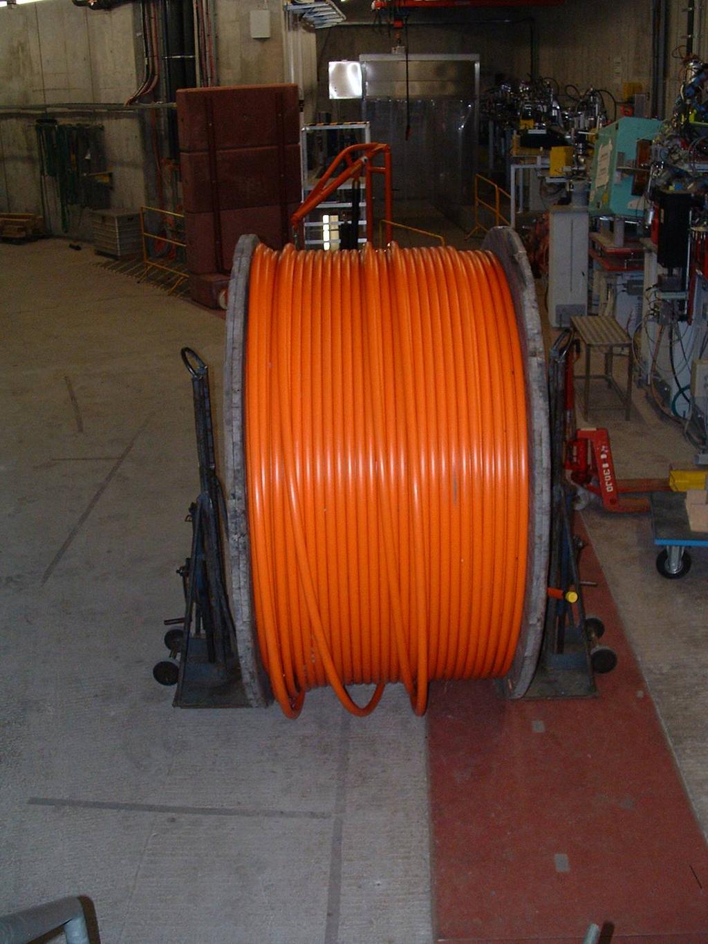
4 Beam pick-up Output signal measured in EOS hutch Isolated impedance-matched ring electrode installed in a thick Flange Broadband signal with more than 5 GHz bandwidth Sampled at zero-crossing with laser pulse

5 Test bench for the arrival-time monitor system
6 Raw data of the EOM detector signal
7 Amplitude of the laser pulses
8 Amplitude of the laser pulses (normalized)
9 Scan of laser pulse over beam pick-up signal
10 Scan of laser pulse over beam pick-up signal
11 Measurement principle and resolution of the EOM detectors Zero-crossing of beam pick-up signal Laser pulses sample beam pick-up signal at zero-crossing Bunch arrival time changes are transferred into laser amplitude changes which are measured The resolution of the system is limited by two things: Steepness of the slope of the beam pick-up signal Precision of laser amplitude detection Typical values for current setup: ~ fs / (% laser amplitude modulation) rms ~ % (recently 0.08%) (unmodulated laser pulses) Resolution of EOM detectors: ~ fs


12 Slow feedback for sample position A slow feedback ensures that the laser pulse always samples the zero-crossing of the beam pick-up signal even if the bunch arrival time changes. Currently the phase of the laser is used as the actuator, but in the final design this will be done by an optical delayline. Large timing changes will be measured and compensated by a coarse measurement (attenuated beam pick-up signal)

13 Comparison measurement between two arrival-time detectors The signal of the beam pick-up was split and connected to the two EOM detectors. The rms-resolution of the detectors was estimated from the laser amplitude noise and the slope from the calibration: Detector 1: 99 fs Detector 2: 114 fs estimated jitter between the two detectors: 151 fs

14 Comparison measurement between two arrival-time detectors rms jitter Detector fs Detector fs Det. 1 Det fs
15 Position dependence of the beam pick-up signal Using the two different output ports of the beam pick-up as input for the EOM detectors gives rms resolutions of about 30 fs for both detectors. But: the measured rms jitter of the difference signal is around 1.5 ps. Orbit dependence of beam pick-up signal!
16 Position dependence of the beam pickup signal The beam arrival time depends linearly on the beam position in x and y: The constants a i were determined by changing the orbit at the pick-up with corrector coils: When using the BPM system (~ 20 μm resolution) to correct for the orbit dependence the remaining rms jitter of the difference signal is still 300 fs (dominated by the BPM system).
17 Combined beam arrival-time and beam position monitor However, we can use the EOM detectors to measure the horizontal beam position: A rms resolution of 33 fs for the EOM detectors and 20 µm for the vertical beam position yields a resolution for the horizontal beam position of 3 µm (rms). This precise beam position we can use to reduce the error in the arrival time from ~ 300 fs to below 30 fs (rms).
18 Bunch arrival-time measurement Time change seen by arrival time monitor: ~ 5 ps / (% ACC1 gradient change) Time change seen by TCAV: ~ 5.8 ps / (% ACC1 gradient change) Intra-bunch train jitter between two adjacent bunches: ~ fs
 ps / mm ax = (-0.191 +- 0.026) ps / mm ay = (0.060 +- 0.032) ps / mm ay = (0.064 +- 0.")
19 Reduction of orbit dependence with cold-combiner beam pick-up To minimize the orbit dependence the two output signals of the beam pick-up were combined with a so-called cold combiner. 50 ohms? Cold combiner to EOM detector measured orbit dependence: ax = ( ) ps / mm ax = ( ) ps / mm ay = ( ) ps / mm ay = ( ) ps / mm Reduction of the horizontal orbit dependence by a factor of 30-50! horizontal beam position [mm] vertical beam position [mm]
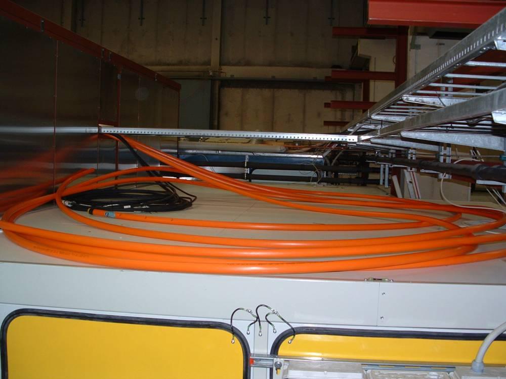
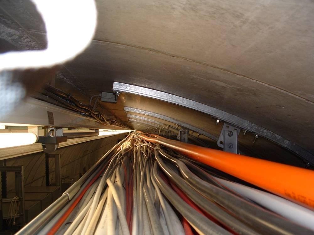
20 Measurement of pick-up signal in the tunnel

21 Charge dependence of BAM measurement with and without limiter Limiter transfers amplitude modulations of the beam pick-up signal to phase changes! The data has to be analyzed in detail, the nonlinearity might be easy to correct

22 Comparison measurement with EOS experiment Arrival time jitter between EOS and BAM is about 300 fs! BAM EOS has clearly the higher resolution. A measurement with the TCAV confirms that this is not due to the difference that EOS detects the high density spike of the electron bunch while the BAM is only sensitive to the center. Source for bad correlation: laser synchronization
23 Phase noise measurement of BAM fiber laser Integrated jitter of reference frequency (10 Hz 100 khz): ~ 120 fs Integrated jitter of Fiber laser (10 Hz 100 khz): ~ fs (depending on settings) The synchronization has been improved meanwhile to about 150 fs jitter with respect to the reference.
24 Measurement of the bunch arrival time over the bunch train Beam loading compensation off ~ 3 ps difference over bunch train ~ 3 ps difference over bunch train Beam loading compensation on (not optimized) ~ 1 ps difference over bunch train
25 Confirmation of high BAM resolution in spite of synchronization problem Jitter between two adjacent bunches: ~ 50 fs
.")
26 Laser amplitude measurement: clock jitter of ADC board With the SIS ADC board which is currently used to detect the amplitude of the laser pulses the resolution is limited to about 0.2 % (best results was ~ 0.12 %). Reason: Clock jitter of ADC board (~ ps peak-peak)
27 Laser Amplitude Measurement: Clock Jitter of ADC Board Why does this clock jitter disturb our measurement? ADC samples different positions of the photo diode signal We need a small ADC clock jitter We have to stretch the pulse With a better ADC (Linear Technology Eval board) the resolution of the readout recently could be improved to ~ 0.08 % (~62 db). This could still be limited by noise on the PD supply voltage.
28 Frontends for the BAM Installed in laser hutch ADC clock limiter filter ~ 980 nm pump light input from fiberlink for ADC clock generation EDFA in out in ADC bias voltage EOM1?? pickup signal limiter / weak attenuator out pulse shaper?? pulse shaper OUT1 high resolution measurement strong attenuator EOM EDFA? EDFA? OUT2 low resolution measurement bias voltage 2 EOM Installed near beam pick-up
29 Outlook The beam pick-up which is installed currently will be replaced by a faster one with a different characteristics: same slope at zero-crossing at much lower peak voltage (design by K. Hacker). The same measurement technique will be used for the large aperture BPMs in the chicanes (K. Hacker) and for the laser arrival time monitor (LAM) for the injector laser (K.H. Matthiesen). Development of the BAM / BPM / LAM front-ends for the installation in the tunnel is ongoing Development of fast ADC board (108 MHz, 16 bit) has been started (F. Ludwig, H.J. Wentzlaff) Study on readout system for the laser amplitude is ongoing to improve the resolution of the system further.
30 Thank you!
31 Dependence of slope of beam pick-up signal on beam position
32 Dependence of slope of beam pick-up signal on beam position
33 Measurement of pick-up signal in the tunnel But: EOMs die when the voltage is too high Limiter or weaker signal needed
Performance Evaluation of the Upgraded BAMs at FLASH
 Performance Evaluation of the Upgraded BAMs at FLASH with a compact overview of the BAM, the interfacing systems & a short outlook for 2019. Marie K. Czwalinna On behalf of the Special Diagnostics team
RF-based Synchronization of the Seed and Pump-Probe Lasers to the Optical Synchronization System at FLASH
 RF-based Synchronization of the Seed and Pump-Probe Lasers to the Optical Synchronization System at FLASH Introduction to the otical synchronization system and concept of RF generation for locking of Ti:Sapphire
RF-Based Detector for Measuring Fiber Length Changes with Sub-5 Femtosecond Long-Term Stability.
 RF-Based Detector for Measuring Fiber Length Changes with Sub-5 Femtosecond Long-Term Stability. J. Zemella 1, V. Arsov 1, M. K. Bock 1, M. Felber 1, P. Gessler 1, K. Gürel 3, K. Hacker 1, F. Löhl 1, F.
Beam Diagnostics, Low Level RF and Feedback for Room Temperature FELs. Josef Frisch Pohang, March 14, 2011
 Beam Diagnostics, Low Level RF and Feedback for Room Temperature FELs Josef Frisch Pohang, March 14, 2011 Room Temperature / Superconducting Very different pulse structures RT: single bunch or short bursts
synchronization system
 Status of the optical synchronization system Holger Schlarb DESY for the LbSyn team V. Arsov, M. C. Behrens, Bock, P. Gessler, M. Felber, K. Hacker, F. Loehl, F. Ludwig, K-H. Matthiesen, B. Schmidt, S.
Installation Progress of the Laser-based Synchronization System at FLASH.
 Installation Progress of the Laser-based Synchronization System at FLASH. Overview, Experiences, Performance and Outlook Sebastian Schulz 1,2 on behalf of the FLASH LbSyn Team 1 Institute of Experimental
Electro-optic Spectral Decoding Measurements at FLASH
 Electro-optic Spectral Decoding Measurements at FLASH, FLA Florian Loehl, Sebastian Schulz, Laurens Wißmann Motivation Development of a robust online bunch length monitor for FLASH and XFEL Transition
Beam Arrival Time Monitors. Josef Frisch, IBIC Sept. 15, 2015
 Beam Arrival Time Monitors Josef Frisch, IBIC Sept. 15, 2015 Arrival Time Monitors Timing is only meaningful relative to some reference, and in general what matters is the relative timing of two different
Feedback Requirements for SASE FELS. Henrik Loos, SLAC IPAC 2010, Kyoto, Japan
 Feedback Requirements for SASE FELS Henrik Loos, SLAC, Kyoto, Japan 1 1 Henrik Loos Outline Stability requirements for SASE FELs Diagnostics for beam parameters Transverse: Beam position monitors Longitudinal:
BEAM ARRIVAL TIME MONITORS
 BEAM ARRIVAL TIME MONITORS J. Frisch SLAC National Accelerator Laboratory, Stanford CA 94305, USA Abstract We provide an overview of beam arrival time measurement techniques for FELs and other accelerators
Electro-Optic Longitudinal Bunch Profile Measurements at FLASH: Experiment, Simulation, and Validation
 Electro-Optic Longitudinal Bunch Profile Measurements at FLASH: Experiment, Simulation, and Validation Bernd Steffen, DESY FEL 2007 Novosibirsk, August 29th 2007 Electro-Optic Bunch Length Detection fs
Femtosecond-stability delivery of synchronized RFsignals to the klystron gallery over 1-km optical fibers
 FEL 2014 August 28, 2014 THB03 Femtosecond-stability delivery of synchronized RFsignals to the klystron gallery over 1-km optical fibers Kwangyun Jung 1, Jiseok Lim 1, Junho Shin 1, Heewon Yang 1, Heung-Sik
EUROFEL-Report-2006-DS EUROPEAN FEL Design Study
 EUROFEL-Report-2006-DS3-034 EUROPEAN FEL Design Study Deliverable N : D 3.8 Deliverable Title: RF Amplitude and Phase Detector Task: Author: DS-3 F.Ludwig, M.Hoffmann, M.Felber, Contract N : 011935 P.Strzalkowski,
ELECTRON BEAM DIAGNOSTICS AND FEEDBACK FOR THE LCLS-II*
 THB04 Proceedings of FEL2014, Basel, Switzerland ELECTRON BEAM DIAGNOSTICS AND FEEDBACK FOR THE LCLS-II* Josef Frisch, Paul Emma, Alan Fisher, Patrick Krejcik, Henrik Loos, Timothy Maxwell, Tor Raubenheimer,
Electro-Optical Measurements at the Swiss Light Source (SLS) Linac at the PSI. First Results
 Linac at the PSI. First Results") Electro-Optical Measurements at the Swiss Light Source (SLS) Linac at the PSI First Results Overview motivation electro-optical sampling general remarks experimental setup synchronisation between TiSa-laser
Electro-Optical Measurements at the Swiss Light Source (SLS) Linac at the PSI First Results Overview motivation electro-optical sampling general remarks experimental setup synchronisation between TiSa-laser
Development of utca Hardware for BAM system at FLASH and XFEL
 Development of utca Hardware for BAM system at FLASH and XFEL Samer Bou Habib, Dominik Sikora Insitute of Electronic Systems Warsaw University of Technology Warsaw, Poland Jaroslaw Szewinski, Stefan Korolczuk
SHF Communication Technologies AG
 SHF Communication Technologies AG Wilhelm-von-Siemens-Str. 23 Aufgang D 12277 Berlin Marienfelde Germany Phone ++49 30 / 772 05 10 Fax ++49 30 / 753 10 78 E-Mail: sales@shf.biz Web: http://www.shf.biz
Specification for Conducted Emission Test
 1 of 10 1. EMI Receiver Frequency range 9kHz 7.0 GHz Measurement time per frequency 10 µs to 100 s time sweep, span = 0 Hz - 1 µs to 16000 s Sweep time in steps of 5 % frequency sweep, span 10 Hz - 2.5
Dark Current Kicker Studies at FLASH
 Dark Current Kicker Studies at FLASH F. Obier, J. Wortmann, S. Schreiber, W. Decking, K. Flöttmann FLASH Seminar, DESY, 02 Feb 2010 History of the dark current kicker 2005 Vertical kicker was installed
RF Locking of Femtosecond Lasers
 RF Locking of Femtosecond Lasers Josef Frisch, Karl Gumerlock, Justin May, Steve Smith SLAC Work supported by DOE contract DE-AC02-76SF00515 1 Overview FEIS 2013 talk discussed general laser locking concepts
CERTIFICATE OF CALIBRATION
 CERTIFICATE OF CALIBRATION Issued by: Pico Technology Ltd. Certificate Number: 9999 of: James House, Colmworth Business Park, St. Neots, Cambridgeshire, Signature: PE19 8YP UNITED KINGDOM Tel: +44 (0)
Status on Pulsed Timing Distribution Systems and Implementations at DESY, FERMI and XFEL
 FLS Meeting March 7, 2012 Status on Pulsed Timing Distribution Systems and Implementations at DESY, FERMI and XFEL Franz X. Kärtner Center for Free-Electron Laser Science, DESY and Department of Physics,
Progress of the TEO experiment at FLASH
 Progress of the TEO experiment at VUV-FEL at DESY - Armin Azima S. Duesterer, J. Feldhaus, H. Schlarb, H. Redlin, B. Steffen, DESY Hamburg K. Sengstock, Uni Hamburg Adrian Cavalieri, David Fritz, David
FLASH at DESY. FLASH. Free-Electron Laser in Hamburg. The first soft X-ray FEL operating two undulator beamlines simultaneously
 FLASH at DESY The first soft X-ray FEL operating two undulator beamlines simultaneously Katja Honkavaara, DESY for the FLASH team FEL Conference 2014, Basel 25-29 August, 2014 First Lasing FLASH2 > First
The CMS ECAL Laser Monitoring System
 The CMS ECAL Laser Monitoring System CALOR 2006 XII INTERNATIONAL CONFERENCE on CALORIMETRY in HIGH ENERGY PHYSICS Adi Bornheim California Institute of Technology Chicago, June 8, 2006 Introduction CMS
Testing with Femtosecond Pulses
 Testing with Femtosecond Pulses White Paper PN 200-0200-00 Revision 1.3 January 2009 Calmar Laser, Inc www.calmarlaser.com Overview Calmar s femtosecond laser sources are passively mode-locked fiber lasers.
SHF Communication Technologies AG
 SHF Communication Technologies AG Wilhelm-von-Siemens-Str. 23D 12277 Berlin Germany Phone ++49 30 772 051-0 Fax ++49 30 753 10 78 E-Mail: sales@shf.de Web: http://www.shf.de Datasheet SHF 46123 A Optical
HIGHER ORDER MODES FOR BEAM DIAGNOSTICS IN THIRD HARMONIC 3.9 GHZ ACCELERATING MODULES *
 HIGHER ORDER MODES FOR BEAM DIAGNOSTICS IN THIRD HARMONIC 3.9 GHZ ACCELERATING MODULES * N. Baboi #, N. Eddy, T. Flisgen, H.-W. Glock, R. M. Jones, I. R. R. Shinton, and P. Zhang # # Deutsches Elektronen-Synchrotron
Terahertz Wave Spectroscopy and Analysis Platform. Full Coverage of Applications From R&D to Industrial Testing
 Terahertz Wave Spectroscopy and Analysis Platform Full Coverage of Applications From R&D to Industrial Testing Terahertz Wave Spectroscopy and Analysis Platform Optimal for a wide range of terahertz research
Low-Level RF. S. Simrock, DESY. MAC mtg, May 05 Stefan Simrock DESY
 Low-Level RF S. Simrock, DESY Outline Scope of LLRF System Work Breakdown for XFEL LLRF Design for the VUV-FEL Cost, Personpower and Schedule RF Systems for XFEL RF Gun Injector 3rd harmonic cavity Main
Sub-ps (and sub-micrometer) developments at ELETTRA
 developments at ELETTRA") Sub-ps (and sub-micrometer) developments at ELETTRA Mario Ferianis SINCROTRONE TRIESTE, Italy The ELETTRA laboratory ELETTRA is a 3 rd generation synchrotron light source in Trieste (I) since 1993 up to
Sub-ps (and sub-micrometer) developments at ELETTRA Mario Ferianis SINCROTRONE TRIESTE, Italy The ELETTRA laboratory ELETTRA is a 3 rd generation synchrotron light source in Trieste (I) since 1993 up to
Directly Chirped Laser Source for Chirped Pulse Amplification
 Directly Chirped Laser Source for Chirped Pulse Amplification Input pulse (single frequency) AWG RF amp Output pulse (chirped) Phase modulator Normalized spectral intensity (db) 64 65 66 67 68 69 1052.4
Beam Stabilization at
 Beam Stabilization at FERMI@EETTR S.Bassanese S.Cleva G.Gaio 1 FERMI s BPM system layout RD_KGxx o o o o Patch B o o o o Panel C o o o o D o o o o B C e - D BPM Trigger pulse RT Data Data Giga bit ETH
Setup of the four-wavelength Doppler lidar system with feedback controlled pulse shaping
 Setup of the four-wavelength Doppler lidar system with feedback controlled pulse shaping Albert Töws and Alfred Kurtz Cologne University of Applied Sciences Steinmüllerallee 1, 51643 Gummersbach, Germany
Timing Noise Measurement of High-Repetition-Rate Optical Pulses
 564 Timing Noise Measurement of High-Repetition-Rate Optical Pulses Hidemi Tsuchida National Institute of Advanced Industrial Science and Technology 1-1-1 Umezono, Tsukuba, 305-8568 JAPAN Tel: 81-29-861-5342;
Functional block diagram for SIS8300. Christian Schmidt for the LLRF team Collaboration workshop
 Functional block diagram for SIS8300 Christian Schmidt for the LLRF team Collaboration workshop 2012 7.08.2012 Outline > Motivation and general comments > Preprocessing LLRF ADC board Block diagram Current
- RF Master-Reference Update (F.Ludwig, H.Weddig - DESY, K.Czuba - TU Warsaw) - Beam Stability Update (C.Gerth, F.Ludwig, G.
 - Beam Stability Update (C.Gerth, F.Ludwig, G.") FLASH Meeting, 21/04/09 Beam Stability at FLASH - update F.Ludwig - DESY Content : - Motivation - RF Master-Reference Update (F.Ludwig, H.Weddig - DESY, K.Czuba - TU Warsaw) - Beam Stability Update (C.Gerth,
FLASH Meeting, 21/04/09 Beam Stability at FLASH - update F.Ludwig - DESY Content : - Motivation - RF Master-Reference Update (F.Ludwig, H.Weddig - DESY, K.Czuba - TU Warsaw) - Beam Stability Update (C.Gerth,
x-ray Beam Size Monitor
 x-ray Beam Size Monitor J. Alexander, N. Eggert, J. Flanagan, W. Hopkins, B. Kreis, M. McDonald, D. Peterson, N. Rider Goals: 2 products: tuning tool with rapid feedback of beam height during LET measurements
INTRA-TRAIN LONGITUDINAL FEEDBACK FOR BEAM STABILIZATION AT FLASH
 INTRA-TRAIN LONGITUDINAL FEEDBACK FOR BEAM STABILIZATION AT FLASH W. Koprek*, C. Behrens, M. K. Bock, M. Felber, P. Gessler, K. Hacker, H. Schlarb, C. Schmidt, B. Steffen, S. Wesch, DESY, Hamburg, Germany
FLASH: Status and upgrade
 : Status and upgrade The User Facility Layout Performance and operational o a issues Upgrade Bart Faatz for the team DESY FEL 2009 Liverpool, UK August 23-28, 2009 at DESY > FEL user facility since summer
Terahertz Wave Spectroscopy and Analysis Platform. Full Coverage of Applications From R&D to Industrial Testing
 Terahertz Wave Spectroscopy and Analysis Platform Full Coverage of Applications From R&D to Industrial Testing Terahertz Wave Spectroscopy and Analysis Platform Optimal for a wide range of terahertz research
SHF Communication Technologies AG
 SHF Communication Technologies AG Wilhelm-von-Siemens-Str. 23D 12277 Berlin Germany Phone ++49 30 772 051-0 Fax ++49 30 753 10 78 E-Mail: sales@shf.de Web: http://www.shf.de Datasheet SHF 46120 B Optical
taccor Optional features Overview Turn-key GHz femtosecond laser
 taccor Turn-key GHz femtosecond laser Self-locking and maintaining Stable and robust True hands off turn-key system Wavelength tunable Integrated pump laser Overview The taccor is a unique turn-key femtosecond
Analogue electronics for BPMs at GSI - Performance and limitations
 Joint ARIES Workshop on Electron and Hadron Synchrotrons Barcelona, 12-14 th November 2018 Analogue electronics for BPMs at GSI - Performance and limitations W. Krämer & W. Kaufmann (GSI) Dept. of Beam
SHF Communication Technologies AG
 SHF Communication Technologies AG Wilhelm-von-Siemens-Str. 23 Aufgang D 12277 Berlin Marienfelde Germany Phone ++49 30 / 772 05 10 Fax ++49 30 / 753 10 78 E-Mail: sales@shf.biz Web: http://www.shf.biz
High-Power Highly Linear Photodiodes for High Dynamic Range LADARs
 High-Power Highly Linear Photodiodes for High Dynamic Range LADARs Shubhashish Datta and Abhay Joshi th June, 6 Discovery Semiconductors, Inc. 9 Silvia Street, Ewing, NJ - 868, USA www.discoverysemi.com
User s Guide Modulator Alignment Procedure
 User s Guide Modulator Alignment Procedure Models 350, 360, 370, 380, 390 series Warranty Information ConOptics, Inc. guarantees its products to be free of defects in materials and workmanship for one
Optical phase-locked loop for coherent transmission over 500 km using heterodyne detection with fiber lasers
 Optical phase-locked loop for coherent transmission over 500 km using heterodyne detection with fiber lasers Keisuke Kasai a), Jumpei Hongo, Masato Yoshida, and Masataka Nakazawa Research Institute of
1550 nm Programmable Picosecond Laser, PM
 1550 nm Programmable Picosecond Laser, PM The Optilab is a programmable laser that produces picosecond pulses with electrical input pulses. It functions as a seed pulse generator for Master Oscillator
Performance of the Prototype NLC RF Phase and Timing Distribution System *
 SLAC PUB 8458 June 2000 Performance of the Prototype NLC RF Phase and Timing Distribution System * Josef Frisch, David G. Brown, Eugene Cisneros Stanford Linear Accelerator Center, Stanford University,
SOLEIL Libera Performance
 SOLEIL Libera Performance Libera Workshop 24/25 September 2007 on behalf of the SOLEIL BPM team BPM system: MAC2 requirements, Feb. 2002 closed orbit Correction number of BPMs 120 instead of 112 single
User s Guide Modulator Alignment Procedure
 User s Guide Modulator Alignment Procedure Models 350, 360, 370, 380, 390 series Warranty Information Conoptics, Inc. guarantees its products to be free of defects in materials and workmanship for one
Optical phase-coherent link between an optical atomic clock. and 1550 nm mode-locked lasers
 Optical phase-coherent link between an optical atomic clock and 1550 nm mode-locked lasers Kevin W. Holman, David J. Jones, Steven T. Cundiff, and Jun Ye* JILA, National Institute of Standards and Technology
FLASH Operation at DESY From a Test Accelerator to a User Facility
 FLASH Operation at DESY From a Test Accelerator to a User Facility Michael Bieler FLASH Operation at DESY WAO2012, SLAC, Aug. 8, 2012 Vocabulary DESY: Deutsches Elektronen-Synchrotron, Hamburg, Germany
SHF Communication Technologies AG
 SHF Communication Technologies AG Wilhelm-von-Siemens-Str. 23D 12277 Berlin Germany Phone ++49 30 / 772 05 10 Fax ++49 30 / 753 10 78 E-Mail: sales@shf.de Web: http://www.shf.de Datasheet SHF 806 E SHF
PCS-150 / PCI-200 High Speed Boxcar Modules
 Becker & Hickl GmbH Kolonnenstr. 29 10829 Berlin Tel. 030 / 787 56 32 Fax. 030 / 787 57 34 email: info@becker-hickl.de http://www.becker-hickl.de PCSAPP.DOC PCS-150 / PCI-200 High Speed Boxcar Modules
HIGH-PRECISION LASER MASTER OSCILLATORS FOR OPTICAL TIMING DISTRIBUTION SYSTEMS IN FUTURE LIGHT SOURCES
 HIGH-PRECISION LASER MASTER OSCILLATORS FOR OPTICAL TIMING DISTRIBUTION SYSTEMS IN FUTURE LIGHT SOURCES Axel Winter, Peter Schmüser, Universität Hamburg, Hamburg, Germany, Frank Ludwig, Holger Schlarb,
Frank Schmidt-Föhre, DESY
 Commissioning of the New Online- Radiation-Monitoring-System at the New European XFEL Injector with First Tests of the High-Sensitivity-Mode for Intra-Tunnel Rack Surveillance Frank Schmidt-Föhre, DESY
ModBox - Spectral Broadening Unit
 ModBox - Spectral Broadening Unit The ModBox Family The ModBox systems are a family of turnkey optical transmitters and external modulation benchtop units for digital and analog transmission, pulsed and
Gas Monitor Detector Electronics
 Gas Monitor Detector Electronics from charged particles to digital value Fini Jastrow, TTF/VUV-FEL TTF/VUV-FEL meeting, meeting, 21. Mar 21. 06Mar 06 The Detector Ion Current Measurement Measured Data
Effects of Intensity and Position Modulation On Switched Electrode Electronics Beam Position Monitor Systems at Jefferson Lab*
 JLAB-ACT--9 Effects of Intensity and Position Modulation On Switched Electrode Electronics Beam Position Monitor Systems at Jefferson Lab* Tom Powers Thomas Jefferson National Accelerator Facility Newport
Electro-optic components and systems Toll Free:
 Electro-optic components and systems Toll Free: 800 748 3349 Laser Modulation Choose from our line of modulators and driver electronics Conoptics manufactures an extensive line of low voltage electro-optic
Femtosecond Synchronization of Laser Systems for the LCLS
 Femtosecond Synchronization of Laser Systems for the LCLS, Lawrence Doolittle, Gang Huang, John W. Staples, Russell Wilcox (LBNL) John Arthur, Josef Frisch, William White (SLAC) 26 Aug 2010 FEL2010 1 Berkeley
THE ORION PHOTOINJECTOR: STATUS and RESULTS
 THE ORION PHOTOINJECTOR: STATUS and RESULTS Dennis T. Palmer SLAC / ARDB ICFA Sardinia 4 July 2002 1. Introduction 2. Beam Dynamics Simulations 3. Photoinjector 1. RF Gun 2. Solenoidal Magnet 3. Diagnostics
A Prototype Wire Position Monitoring System
 LCLS-TN-05-27 A Prototype Wire Position Monitoring System Wei Wang and Zachary Wolf Metrology Department, SLAC 1. INTRODUCTION ¹ The Wire Position Monitoring System (WPM) will track changes in the transverse
Paul Scherrer Institute Pierre-André Duperrex. On-line calibration schemes for RF-based beam diagnostics
 Paul Scherrer Institute Pierre-André Duperrex On-line calibration schemes for RF-based beam diagnostics HB2012 Beijing, 17-20 Sept. 2012 Motivation Current monitor Some difficulties related to RF signal
Measuring Photonic, Optoelectronic and Electro optic S parameters using an advanced photonic module
 Measuring Photonic, Optoelectronic and Electro optic S parameters using an advanced photonic module APPLICATION NOTE This application note describes the procedure for electro-optic measurements of both
SUPPLEMENTARY INFORMATION
 Soliton-Similariton Fibre Laser Bulent Oktem 1, Coşkun Ülgüdür 2 and F. Ömer Ilday 2 SUPPLEMENTARY INFORMATION 1 Graduate Program of Materials Science and Nanotechnology, Bilkent University, 06800, Ankara,
Jungwon Kim, Jonathan A. Cox, Jian J. Chen & Franz X. Kärtner. Department of Electrical Engineering and Computer Science and Research Laboratory
 1 Supplementary Information Drift-free femtosecond timing synchronization of remote optical and microwave sources with better than 10-19 -level stability Jungwon Kim, Jonathan A. Cox, Jian J. Chen & Franz
Supplementary Materials for
 advances.sciencemag.org/cgi/content/full/2/4/e1501489/dc1 Supplementary Materials for A broadband chip-scale optical frequency synthesizer at 2.7 10 16 relative uncertainty Shu-Wei Huang, Jinghui Yang,
Continuous-Wave (CW) Single-Frequency IR Laser. NPRO 125/126 Series
 Single-Frequency IR Laser. NPRO 125/126 Series") Continuous-Wave (CW) Single-Frequency IR Laser NPRO 125/126 Series www.lumentum.com Data Sheet The Lumentum NPRO 125/126 diode-pumped lasers produce continuous-wave (CW), singlefrequency output at either
Continuous-Wave (CW) Single-Frequency IR Laser NPRO 125/126 Series www.lumentum.com Data Sheet The Lumentum NPRO 125/126 diode-pumped lasers produce continuous-wave (CW), singlefrequency output at either
Kit for building your own THz Time-Domain Spectrometer
 Kit for building your own THz Time-Domain Spectrometer 16/06/2016 1 Table of contents 0. Parts for the THz Kit... 3 1. Delay line... 4 2. Pulse generator and lock-in detector... 5 3. THz antennas... 6
Characteristics of point-focus Simultaneous Spatial and temporal Focusing (SSTF) as a two-photon excited fluorescence microscopy
 as a two-photon excited fluorescence microscopy") Characteristics of point-focus Simultaneous Spatial and temporal Focusing (SSTF) as a two-photon excited fluorescence microscopy Qiyuan Song (M2) and Aoi Nakamura (B4) Abstracts: We theoretically and experimentally
Characteristics of point-focus Simultaneous Spatial and temporal Focusing (SSTF) as a two-photon excited fluorescence microscopy Qiyuan Song (M2) and Aoi Nakamura (B4) Abstracts: We theoretically and experimentally
Optical Transport Tutorial
 Optical Transport Tutorial 4 February 2015 2015 OpticalCloudInfra Proprietary 1 Content Optical Transport Basics Assessment of Optical Communication Quality Bit Error Rate and Q Factor Wavelength Division
12/08/2003 H. Schlarb, DESY, Hamburg
 K. Bane, F.-J. Decker, P. Emma, K. Hacker, L. Hendrickson,, C. L. O Connell, P. Krejcik,, H. Schlarb*, H. Smith, F. Stulle*, M. Stanek, SLAC, Stanford, CA 94025, USA * σ z NDR 6 mm 1.2 mm 3-stage compression
Spectral phase shaping for high resolution CARS spectroscopy around 3000 cm 1
 Spectral phase shaping for high resolution CARS spectroscopy around 3 cm A.C.W. van Rhijn, S. Postma, J.P. Korterik, J.L. Herek, and H.L. Offerhaus Mesa + Research Institute for Nanotechnology, University
User s Guide Modulator Alignment Procedure
 User s Guide Modulator Alignment Procedure Models 350, 360, 370, 380, 390 series Warranty Information ConOptics, Inc. guarantees its products to be free of defects in materials and workmanship for one
SUPPLEMENTARY INFORMATION DOI: /NPHOTON
 Supplementary Methods and Data 1. Apparatus Design The time-of-flight measurement apparatus built in this study is shown in Supplementary Figure 1. An erbium-doped femtosecond fibre oscillator (C-Fiber,
LCLS Injector Diagnostics. Henrik Loos. Diagnostics overview Transverse Beam Properties Longitudinal Beam Properties
 Diagnostics overview Transverse Beam Properties Longitudinal Beam Properties LCLS Diagnostics Tasks Charge Toroids (Gun, Inj, BC, Und) Faraday cups (Gun & Inj) Trajectory & energy Stripline BPMs (Gun,
Advanced Photon Source Monopulse rf Beam Position Monitor Front-End Upgrade*
 Advanced Phon Source Monopulse rf Beam Position Monir Front-End Upgrade* Robert M. Lill and Glenn A. Decker Advanced Phon Source, Argonne National Laborary 9700 South Cass Avenue, Argonne, Illinois 60439
NON-AMPLIFIED HIGH SPEED PHOTODETECTOR USER S GUIDE
 NON-AMPLIFIED HIGH SPEED PHOTODETECTOR USER S GUIDE Thank you for purchasing your Non-amplified High Speed Photodetector. This user s guide will help answer any questions you may have regarding the safe
Dark current Monitor for the European XFEL D. Lipka, W. Kleen, J. Lund-Nielsen, D. Nölle, S. Vilcins, V. Vogel; DESY Hamburg
 Dark current Monitor for the European XFEL D. Lipka, W. Kleen, J. Lund-Nielsen, D. Nölle, S. Vilcins, V. Vogel; DESY Hamburg Content 2 Dark current Principle of detecting weakly charged bunches with resonator
Activities on Beam Orbit Stabilization at BESSY II
 Activities on Beam Orbit Stabilization at BESSY II J. Feikes, K. Holldack, P. Kuske, R. Müller BESSY Berlin, Germany IWBS`02 December 2002 Spring 8 BESSY: Synchrotron Radiation User Facility BESSY II:
Performance of Microchannel Plates Fabricated Using Atomic Layer Deposition
 Performance of Microchannel Plates Fabricated Using Atomic Layer Deposition Andrey Elagin on behalf of the LAPPD collaboration Introduction Performance (timing) Conclusions Large Area Picosecond Photo
Coherent Synchrotron Radiation in the ANKA Storage Ring
 Coherent Synchrotron Radiation in the ANKA Storage Ring Marcel Schuh On behalf of the ANKA THz-Group Laboratory for Applications of Synchrotron Radiation (LAS) / Institute of Synchrotron Radiation (ISS)
Implementation of A Nanosecond Time-resolved APD Detector System for NRS Experiment in HEPS-TF
 Implementation of A Nanosecond Time-resolved APD Detector System for NRS Experiment in HEPS-TF LI Zhen-jie a ; MA Yi-chao c ; LI Qiu-ju a ; LIU Peng a ; CHANG Jin-fan b ; ZHOU Yang-fan a * a Beijing Synchrotron
Orbit Stability Challenges for Storage Rings. Glenn Decker Advanced Photon Source Beam Diagnostics March 8, 2012
 Orbit Stability Challenges for Storage Rings Glenn Decker Advanced Photon Source Beam Diagnostics March 8, 2012 Outline Beam stability requirements RF beam position monitor technology NSLS II developments
SHF Communication Technologies AG. Wilhelm-von-Siemens-Str. 23D Berlin Germany. Phone Fax
 SHF Communication Technologies AG Wilhelm-von-Siemens-Str. 23D 12277 Berlin Germany Phone +49 30 772051-0 Fax ++49 30 7531078 E-Mail: sales@shf.de Web: http://www.shf.de Datasheet SHF 100 BPP Broadband
Radio over Fiber technology for 5G Cloud Radio Access Network Fronthaul
 Radio over Fiber technology for 5G Cloud Radio Access Network Fronthaul Using a highly linear fiber optic transceiver with IIP3 > 35 dbm, operating at noise level of -160dB/Hz, we demonstrate 71 km RF
Designing for Femtosecond Pulses
 Designing for Femtosecond Pulses White Paper PN 200-1100-00 Revision 1.1 July 2013 Calmar Laser, Inc www.calmarlaser.com Overview Calmar s femtosecond laser sources are passively mode-locked fiber lasers.
A prototype S-band BPM system for the ILC energy spectrometer
 EUROTeV-Report-2008-072 A prototype S-band BPM system for the ILC energy spectrometer A. Lyapin, B. Maiheu, D. Attree, M. Wing, S. Boogert, G. Boorman, M. Slater, D. Ward January 12, 2009 Abstract This
NON-AMPLIFIED PHOTODETECTOR USER S GUIDE
 NON-AMPLIFIED PHOTODETECTOR USER S GUIDE Thank you for purchasing your Non-amplified Photodetector. This user s guide will help answer any questions you may have regarding the safe use and optimal operation
FLASH II. FLASH II: a second undulator line and future test bed for FEL development.
 FLASH II FLASH II: a second undulator line and future test bed for FEL development Bart.Faatz@desy.de Outline Proposal Background Parameters Layout Chalenges Timeline Cost estimate Personnel requirements
200 MHz Variable Gain Photoreceiver
 The image shows model -FST with 1.035-40 threaded flange and coupler ring. Features Applications Adjustable transimpedance gain from 10 2 to 10 8 V/A Wide bandwidth up to 200 MHz Si-PIN photodiode covering
Bunch-by-Bunch Broadband Feedback for the ESRF
 Bunch-by-Bunch Broadband Feedback for the ESRF ESLS RF meeting / Aarhus 21-09-2005 J. Jacob, E. Plouviez, J.-M. Koch, G. Naylor, V. Serrière Goal: Active damping of longitudinal and transverse multibunch
Synchronization Overview
 Synchronization Overview S. Simrock, DESY ERL Workshop 2005 Stefan Simrock DESY What is Synchronization Outline Synchronization Requirements for RF, Laser and Beam Timing stability RF amplitude and phase
Commissioning Status and Results of ATLAS Level1 Endcap Muon Trigger System. Yasuyuki Okumura. Nagoya TWEPP 2008
 Commissioning Status and Results of ATLAS Level1 Endcap Muon Trigger System Yasuyuki Okumura Nagoya University @ TWEPP 2008 ATLAS Trigger DAQ System Trigger in LHC-ATLAS Experiment 3-Level Trigger System
The Lightwave Model 142 CW Visible Ring Laser, Beam Splitter, Model ATM- 80A1 Acousto-Optic Modulator, and Fiber Optic Cable Coupler Optics Project
 The Lightwave Model 142 CW Visible Ring Laser, Beam Splitter, Model ATM- 80A1 Acousto-Optic Modulator, and Fiber Optic Cable Coupler Optics Project Stephen W. Jordan Seth Merritt Optics Project PH 464
HIGH SPEED FIBER PHOTODETECTOR USER S GUIDE
 HIGH SPEED FIBER PHOTODETECTOR USER S GUIDE Thank you for purchasing your High Speed Fiber Photodetector. This user s guide will help answer any questions you may have regarding the safe use and optimal
레이저의주파수안정화방법및그응용 박상언 ( 한국표준과학연구원, 길이시간센터 )
") 레이저의주파수안정화방법및그응용 박상언 ( 한국표준과학연구원, 길이시간센터 ) Contents Frequency references Frequency locking methods Basic principle of loop filter Example of lock box circuits Quantifying frequency stability Applications
레이저의주파수안정화방법및그응용 박상언 ( 한국표준과학연구원, 길이시간센터 ) Contents Frequency references Frequency locking methods Basic principle of loop filter Example of lock box circuits Quantifying frequency stability Applications