Linac Coherent Light Source (LCLS) Low Level RF Status LCLS FAC. October 30, 2007
|
|
|
- Anne Hudson
- 5 years ago
- Views:
Transcription
1 Linac Coherent Light Source (LCLS) Low Level RF Status LCLS
2 Emma

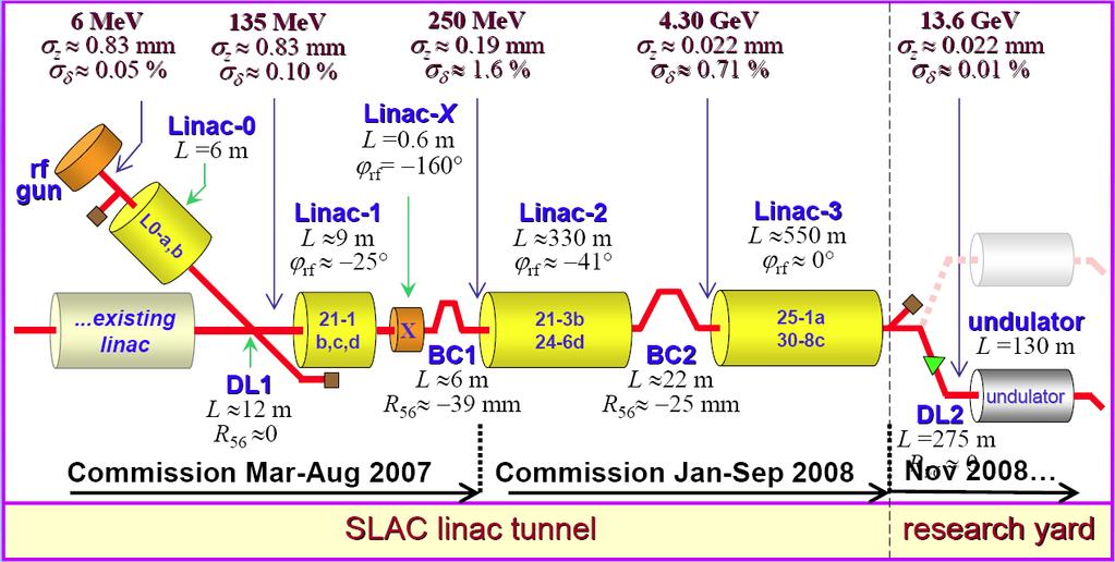
3 LCLS RF Gun, L0, and L1 Emma

4 Dual Feed L0A L0B L0A 57MV 19MV/m L0B 72MV 24MV/m Off Axis Injector Vault

5 Injector Transverse Accelerator 55cm 1MV Powered from 20-5 Linac Klystron Accelerator Output. The klystron station is up stream of LCLS. The transverse accelerator is located in the off axis injector.

6 Calibration to Degrees of S-Band Emma

7 Located between L0A and L0B. Single cell cavity at 2805MHz. 51MHz below RF frequency to lower from dark current generated in the RF Gun. 2805MHz is 25.5MHz below Local Oscillator to enable beam phase measurement against LO reference. Measurement below correlates differences in beam phase between cavities before and after BC1 to bunch length. Beam Phase Cavity Frequency = 2805MHz Q Loaded β=1 = 6200 Time Constant = 700nS Temperature Coefficient = 50kHz/ C

8 Beam Phase Cavity Analysis Phase Slope gives Frequency Time Calculated Beam Phase at Beam Time Measured Phase Data Point 1 Measured Phase Data Point 2 Beam Phase and Cavity Frequency are Calculated from Two Data Points Sent From the PAD. Software remains to be commissioned.


9 X-Band Structure in Main Linac 20MV - 33MV/m 15MW at structure 22MW at the klystron 120nS fill time. Beam at +160degrees 20 from decelerating crest Needs new TWT driver

10 X-Band Station to Linearize Energy Position Correlation Emma
11 LCLS RF Jitter Tolerance Budget 0.50 Lowest Noise Floor Requirement 0.5deg X-Band = 125fS Structure Fill time = 100nS Noise floor = 11GHz 10MHz BW 476MHz X-band X- RMS tolerance budget for <12% rms peak-current jitter or <0.1% rms final e energy jitter. All tolerances are rms levels and the voltage and phase tolerances per klystron for L2 and L3 are Nk larger, assuming uncorrelated errors, where Nk is the number of klystrons per linac. P. Emma
12 Slow Drift Tolerance Limits (Top 4 rows for Δε/ε < 5%, bottom 4 limited by feedback dynamic range) Gun-Laser Timing Bunch Charge Gun RF Phase Gun Relative Voltage L0,1,X,2,3 RF Phase (approx.) L0,1,X,2,3 RF Voltage (approx.) ±2.4* ±3.2 ±2.3 ±0.6 ±5 ±5 deg-s % deg-s % deg-s % (Tolerances are peak values, not rms) P. Emma, J. Wu * for synchronization, this tolerance might be set to ±1 1 ps (without arrival-time measurement)
13 Linac Sector 0 RF Upgrade LCLS must be compatible with the existing linac operation including PEP timing shifts Master Oscillator is located 1.3 miles from LCLS Injector Measurements on January 20, 2006 at Sector 21 show 30fS rms jitter in a bandwidth from 10Hz to 10MHz 1 MAIN LINAC (SECTOR 0) RF/TIMING SYSTEM 476MHz MASTER OSCILLATOR PEP PHASE SHIFTER Degrees in 0.5mS 360Hz Line Sync. IQPAU PEP Control Camac Module 360Hz MASTER AMPLIFIERS 476MHz SLC COUNTDOWN CHASSIS 476MHz Divide to 8.5MHz 8.5MHz Master Trigger Generator MTG Syncs Fiducial to 8.5MHz Damping Ring and 360Hz Power Line Sum Fiducial to RF 1.3 Miles to LCLS Injector Fiducial Generator Syncronized to: 360Hz Power Line 8.5MHz Damping Ring 476MHz RF Distribution PEP PHASE SHIFT ON MAIN DRIVE LINE MDL RF with TIMING Pulse Sync to DR


14 RF Distribution Lab vs. MDL Measurements Existing Linac MDL Sector 0 Before July 2007 LCLS Reference System Lab Measurements 20fS rms Jitter 10Hz to 10MHz John Byrd LBNL 126fS rms Jitter 10Hz to 10MHz In July 2007 both the Master Oscillator and Master Amplifier were upgraded. An increase in stability was noticed.
15 Sector 20 RF Distribution Main Drive Line (MDL) 476MHz RF 360Hz Fiducial From Sector 0 (2km) MDL from Sector 0 TIMING Existing Sector 21 TIMING SYSTEM FIDO Output 120Hz 119MHz TRBR CH2 - S21 119MHz REF PAD CH3 - LCLS 119MHz LSR PAD LASER +13dBm in 476MHz to 2856MHz MULTIPLIER +17dBm out +6dBm in X-Band 4x MULTIPLIER FSJ dB/30ft +17dBm out MDL 476MHz MDL SPAC Track/Hold TRBR 119MHz 0dBm OUT 2856MHz from Sector 21 SBDU LCLS VHF Dual Dist 4x 119MHz 13dBm OUT RF HUT Coupler 476MHz Ref. 80uW LCLS LLRF 476MHz Linac Ref MHz Amp 30dB Gain 19dBm LCLS 476MHz PLL RFR SPAC Sample and Hold PLL with DAC offset adjust and Error Monitor 4x 476MHz 13dBm OUT x 476MHz 13dBm OUT 2856MHz S-Band 10W Amp MHz -20dBm GHz Distribution Gun L0A L0B L0TCAV L1S L1X LINAC EXPERIMENTS +13dBm in 476MHz to 2856MHz MULTIPLIER +17dBm out RF Reference - S-Band 4 x +13dBm out J15 J14 J15 J14 Clock - 102MHz CLK SPAC MHz VHF 5W Amplifier 102MHz 16 Way Dist 22dBm each Gun L0A L0B L0TCAV L1S L1X CH0-2856MHz REF PAD CH1 - S MHz REF PAD LASER 476MHz LSR SPAC MHz LO Gen 2856MHz in IQ Modulator to adjust MHz to 2856MHz Phase Divide 112 to 25.5MHz SSB Mix to MHz 4X to 102MHz 25.5MHz out J15 102MHz out MHz out J15 102MHz 16 Way Dist 22dBm each Local Osc - S-Band LCL SPAC J J MHz S-Band 10W Amp MDL to Linac Sectors 21 to 30 PEP and Research Yard VME BASED LASER PHASE FEEDBACK J15 J MHz -23dBm GHz Distribution CH0-2856MHz LSR PAD CH2-119MHz LSR PAD CH1-2856MHz LSR PAD +13dBm 25.5MHz in X-Band LO Gen 25.5MHz out Gun L0A L0B L0TCAV L1S L1X LASER Reference CH3-25.5MHz REF PAD LASER ROOM LASER Diode Output 2856MHz and 119MHz LASER SINGLE PULSE MEASUREMENT MHz LO from this distribution chassis is the RF Reference for LCLS RF systems.


 for critical")
16 LCLS LLRF System to BC1 RF Feedback for Six RF Stations Gun 5 Chassis L0A 4 Chassis L0B 4 Chassis TCav 4 Chassis L1S 4 Chassis L1X 4 Chassis Laser Reference and Feedback 2 Chassis Two Phase Cavities 1 Chassis Reference System 21 Chassis Total of 49 SLAC built RF chassis were installed and turned on last run. Four short racks in a temperature controlled RF Hut contain the RF reference system as well as Phase and Amplitude Detectors (PADs) for critical RF measurements.

17 LCLS New Reference System Lab Measurements Lab Tests Show Reference System Noise Levels Meet All LCLS Requirements 2856MHz = 70fSrms MHz = 70fSrms 25.5MHz = 2pSrms 102MHz = 2pSrms 2856MHz : 22fSrms 10Hz to 10MHz MHz : 22fSrms 10Hz to 10MHz John Byrd - LBNL 25.5MHz : 152fSrms 10Hz to 1MHz 102MHz : 281fSrms 10Hz to 10MHz


18 RF Cable Routing All cables are routed from devices in temperature stabilized area to the centrally located, temperature stabilized, RF Hut in the linac gallery. RFHUT Cables run down through penetration which is enclosed by the RF Hut Cables from penetration to RF Racks
19 Linac Sector 0 RF MDL L0, L1-5 Klystrons Specifications 100fS rms jitter +-2.3pS drift L2-4 Sectors Specifications 70fS rms jitter +-5pS drift L3-6 Sectors Specifications 150fS rms jitter +-5pS drift RF System Cables / Specifications Laser RF Gun L0A Phase Cavity L0B L1S L1X L2 Ref Number of cables per device Reference cables are 8ft and can drift +-50fS Reference MHz LO PADs Laser RF Gun L0A Phase Cavity L0B L1S L1X L2 Ref Cable Drift Based on Temperature variations and temp co of 5ppm/degC +-290fS +-370fS +-310fS +-240fS +-240fS +-140fS +-160fS +-500fS Most Devices are in Tunnel Laser RF Gun L0A Phase Cavity L0B L1S L1X L2 Ref RF HUT LCLS Specifications: Laser, RF Gun 2.3pS L0A, L0B, L1S, L1X, L2, L3 5pS
20 Existing Phase Reference Line 20mW Existing System SLAC Linac RF New Control To Next Klystron Phase & Amplitude Detector 1W MDL 476MHz -45dB 1mW 6 X 2856MHz Next Sector SubBooster Sub Drive Line 3kW 4IPA High Power Phase Shifter Attenuator Klystron SLED 200MW Accelerator The new control system will tie in to the IPA Chassis with 800W of drive power available. The RF Reference will be from the new RF reference system. 2 RF Solid State Sub-Booster PAC I and Q will be controlled by the PAC chassis, running 16bit DACs at 102MHz. Waveforms to the DACs will be set in an FPGA through a microcontroller running EPICS on RTEMS. 3 I Q LO New RF Ref 1
 Need to change to 48V pulse on Twin BNC connector.")
21 1 kw Solid State S-Band Amplifiers >800W peak at 2856MHz 5 units installed and operational last run Added phase noise not measurable Trigger comes from Beam Containment System (BCS) Need to change to 48V pulse on Twin BNC connector. Amplifier module from Microwave Amplifiers Ltd.


22 RF INPUT Monitor FP N PAC Chassis RF OUTPUT RF OUTPUT Monitor To SSSB FP N RP N I MONITOR FP BNC Q MONITOR FP BNC ACCELERATE TRIGGER 120Hz RP BNC CLOCK 119MHz RP N TRIGGER Monitor TTL FP BNC STANDBY TRIGGER 120Hz RP BNC SSSB Gate Monitor FP BNC SSSB Chassis RP 15 Pin D 2856MHz Ref -3dBm RP N Amp 2 RF Module RF MATCHING FILTER NETWORK 3 I Q 4 MATCHING FILTER NETWORK I&Q MODULATOR LO 1 Amp I J5 Q J4 H9 H10 J3 J2 H7 J10 SSSB H6 P5 Trig TTL 17 to 30uS AD8099 Diff Amp I MAX X 16 bit DAC 119MHz Clock (1MHz to 200MHz) Q 16bit DATA CLK 16bit DATA CLK Control XILINX SPARTAN 3 FPGA Control 16 bit DATA CS/ CLK CONTROL / Arcturus uc5282 Microcontroller Module with 10/100 Ethernet ETHERNET RAW ETHERNET COM 15VDC 70mA RF INPUT Monitor Diode FP BNC 5VDC 10mA 15VDC 70mA NC Temperature Monitor t H12 SLOW ADCs PAC Temp IQ Temp SSSB Temp SSSB P-FWD SSSB P-RFL SSSB PWR +5V -12V Temperature t Monitor Control Board S-Band PAC chassis has an EPICS on RTEMS Coldfire IOC used to load registers and waveform memory on an FPGA. On a trigger the FPGA puts out two 2048 point waveforms which run I and Q inputs on an RF modulator. In calibration mode a single side band modulator is created by sine and cosine waveforms on the I and Q channels.

23 PAC IOC EPICS Panels Operational PAC Panel Calibration PAC Panel In operation mode the PAC receives PVs I Adjust and Q Adjust which are used to transform a preloaded waveform and then load the FPGA. A future upgrade will have the FPGA transform the I and Q waveforms with the loading of 4 matrix elements. In calibration mode the I and Q Offsets are determined to minimize feedthrough in the RF modulator with the gains set to zero. The modulator gains are then set to maximum and then adjusted down to suppress the opposite sideband in a Single Side Band modulator.

24 Operational PACs Four Ref. System Laser Gun L0-A L0-B TCav L1-S L1-X
25 CHAN 0 RF INPUT RP N J22 CHAN 0 TEST PORT FP N J2 LO DIODE DETECTOR LO INPUT MHz RP N J24 LO OUTPUT MHz FP N J9 CHAN 1 TEST PORT FP N J4 CHAN 1 RF INPUT RP N J26 PAD Chassis CPL7 IF RF LO MIXER MIXER RF LO IF CHAN 0 TEST PORT RP SMA J18 FILTER 25.5MHz BP CHAN MHz IF FP BNC J1 RF Board 2 2 Chan RF Heads FILTER 25.5MHz BP Temperature Monitor t 10dBm 4 X 16 bit ADC 102MHz Clock LTC2208 Transformer Coupled Inputs 16bit DATA Chan. 0 Chan. 1 Chan. 2 Chan. 3 CLOCK INCLOCK Mon 102MHz 102MHz RP N J16 FP N J11 WCLK 16bit DATA WCLK 16bit DATA WCLK 16bit DATA WCLK 5VDC 0.8A x 2 Analog FIFO 64k words FIFO 64k words FIFO 64k words Control Control Board FIFO 64k words CPLD 5VDC 0.5A Digital TRIG In 120Hz RP BNC 16 bit DATA J17 CS/ CLK CONTROL / Arcturus uc5282 Microcontroller Module with 10/100 Ethernet TRIG Mon FP BNC J12 QSPI ETHERNET COM RAW ETHERNET 20 pin ribbon J14 J15 J13 CHAN 1 TEST PORT RP SMA J20 CHAN MHz IF FP BNC J3 S-Band PAC chassis has an EPICS on RTEMS Coldfire IOC which reads 4 FIFOs from the 16 bit 102MHz ADCs. The 4 channel control board is connected to two RF heads, each of which has 2 channels. The RF is down mixed with the MHz LO reference to 25.5MHz IF, which is digitized at 102MHz. The IOC does the down conversion to base band, averages over a specified number of points, up to 512, and the set the EPICS I and Q records.

26 PAD Testing Chan 0 SNR 69dB Chan 1 Crosstalk < 100dB Plots with +2dBm into chan plots taken per board. Sine Wave Histogram shows no missing bits and Differential Nonlinearity of ±0.2 LSBs. The Integral Nonlinearity is large due to nonlinearities in the function generator used. The lower SNR of 69dB is due mainly to the 4:1 impedance transformers used on both clock and signal inputs.

27 PAD IOC EPICS Panel The Coldfire EPICS IOC reads digitized data from 4 FIFOs. A window is set in the data by selecting an offset and window size. The data within the window is down converted to baseband and an average I and Q calculated. The data shown here is from station L1S, a SLED cavity is used to power 3 accelarator structures. Channel 0 is the Input to the B structure, channels 1, 2, and 3 are outputs to the B, C, and D structures. The temperature monitors are shown here not working, we have more work to do.
 L1-S")

28 Operational PADs Reference System Laser Gun L0 (A&B) L1-S TCav X-Band Phase Cavity Six Klystron diagnostic L0 A and B PAD Gun 1 PAD

29 VME Based Feedback IOC VME based feedback IOC takes data from the PAD I and Q PVs. The I and Q PVs are transformed to phase and amplitude. The phase has a phase offset applied to align 0 phase with peak acceleration and the amplitude has a scale factor applied to read in electron energy gain on crest. The feedback used a weighted average of the 4 PAD channels to determine a phase and amplitude value for the 2 separate feedbacks. After feedback corrections are done the phase and amplitude are converted to I and Q and the new values sent to the PAD.
 for 10 minutes with feedback on.")

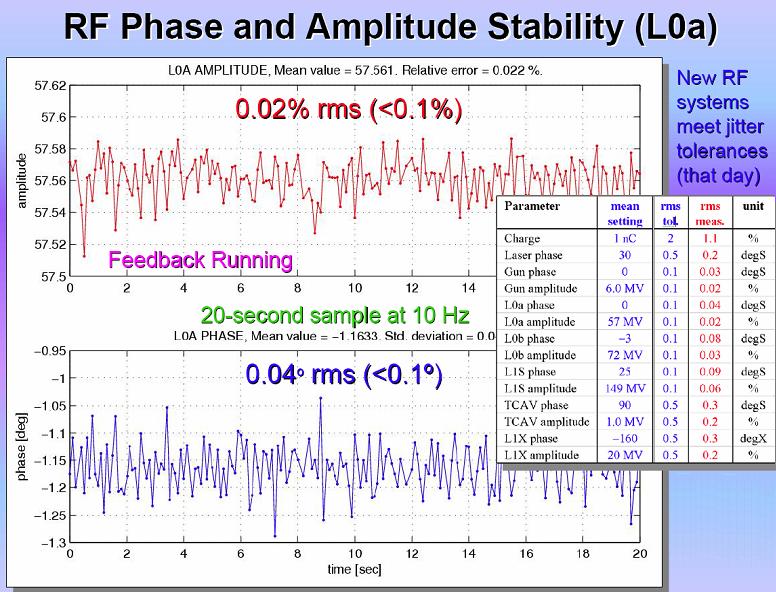
30 L1S Stability Feedback Off, 10 Minutes, 0.056%, 0.13º Feedback On, 10 Minutes, 0.050%, 0.102º L1S Meets Jitter Specifications (0.1% 0.1º) for 10 minutes with feedback on. All stations except X-Band met specifications consistently near the end of the run. The above data was taken with Matlab routines reading the EPICS records from the VME based feedback.
31 Emma
32 LCLS RF System Remaining Tasks Turn On December weeks Control of 3 RF stations for L2 Two Sector Controls (16 RF stations) for L3 Transverse Cavity Control Phase Reference Line in Tunnel (8 Sectors) Two Beam Phase Cavities Modifications to 4 SSSB Chassis for new BCS New Phase Locked Oscillator under design for Injector Software for all above systems
33 Sector 20 RF Hut MHz Ref MHz +17dBm GHz Distribution Block Diagram LCLS RF System L2 and L3 S24 RF Rack LKF2414 Sector 24 S-Band Reference S MHz Ref in S-Band PAC 24-1 S-Band PAC Clock Generation and Amplifier S-Band PAC SSSB SSSB Clock Distribution S-Band PAC SSSB PAD Kly 24-8 CH0 PAC out CH1 Drive S-Band PAC SSSB Penetration S21 to S24 Rigid Coax Linac Tunnel CH2 Beam Voltage CH3 Kly Forward PAD CH0 TCav in CH1 TCav out CH2 PH CH3 S MHz Ref LO Amp/Distribution MHz -3dBm in MHz 4 x 20dBm out MHz in MHz out Penetration Penetration 29-1 S24 to S30 Rigid Coax Linac Tunnel Sector MHz PAC SB Patch Panel TCav Input Reflected TCav Output Reflected Phase Cavity PAD 476MHz PAC SB29 CH0 CH1 CH2 PH04 Sector 29 CH3 S30 Ref Sector 29 KF29-1A Of 18 RF Chassis, 13 are Fabricated.
34 LLRF Software Tasks To be completed before next run begins Migration of code installation (from afs to nfs) Addition of private ethernet for PAD->VME and VME->PAC traffic Sector 24 PACs software L2 TCav software L2 Phase cavity software To be completed during next run Laser upgrade commissioning L2 commissioning of RF systems L2 longitudinal feedback commissioning
35 LCLS LLRF Summary Will have most hardware installed by February 08. Software development is ongoing. Beam synchronous acquisition and 120Hz feedback efforts will continue through the run. This is the largest effort remaining in the LLRF system. Need new type of X-Band Sub-Booster to drive klystron. Will be looking at NLC design TWTs and solid state The above work completes the LCLS LLRF system.
Beam Diagnostics, Low Level RF and Feedback for Room Temperature FELs. Josef Frisch Pohang, March 14, 2011
 Beam Diagnostics, Low Level RF and Feedback for Room Temperature FELs Josef Frisch Pohang, March 14, 2011 Room Temperature / Superconducting Very different pulse structures RT: single bunch or short bursts
Performance of the Prototype NLC RF Phase and Timing Distribution System *
 SLAC PUB 8458 June 2000 Performance of the Prototype NLC RF Phase and Timing Distribution System * Josef Frisch, David G. Brown, Eugene Cisneros Stanford Linear Accelerator Center, Stanford University,
Low-Level RF. S. Simrock, DESY. MAC mtg, May 05 Stefan Simrock DESY
 Low-Level RF S. Simrock, DESY Outline Scope of LLRF System Work Breakdown for XFEL LLRF Design for the VUV-FEL Cost, Personpower and Schedule RF Systems for XFEL RF Gun Injector 3rd harmonic cavity Main
RF Locking of Femtosecond Lasers
 RF Locking of Femtosecond Lasers Josef Frisch, Karl Gumerlock, Justin May, Steve Smith SLAC Work supported by DOE contract DE-AC02-76SF00515 1 Overview FEIS 2013 talk discussed general laser locking concepts
LNS ultra low phase noise Synthesizer 8 MHz to 18 GHz
 LNS ultra low phase noise Synthesizer 8 MHz to 18 GHz Datasheet The LNS is an easy to use 18 GHz synthesizer that exhibits outstanding phase noise and jitter performance in a 3U rack mountable chassis.
RF-based Synchronization of the Seed and Pump-Probe Lasers to the Optical Synchronization System at FLASH
 RF-based Synchronization of the Seed and Pump-Probe Lasers to the Optical Synchronization System at FLASH Introduction to the otical synchronization system and concept of RF generation for locking of Ti:Sapphire
Femtosecond Synchronization of Laser Systems for the LCLS
 Femtosecond Synchronization of Laser Systems for the LCLS, Lawrence Doolittle, Gang Huang, John W. Staples, Russell Wilcox (LBNL) John Arthur, Josef Frisch, William White (SLAC) 26 Aug 2010 FEL2010 1 Berkeley
Borut Baricevic. Libera LLRF. 17 September 2009
 Borut Baricevic Libera LLRF borut.baricevic@i-tech.si 17 September 2009 Outline Libera LLRF introduction Libera LLRF system topology Signal processing structure GUI and signal acquisition RF system diagnostics
THE ORION PHOTOINJECTOR: STATUS and RESULTS
 THE ORION PHOTOINJECTOR: STATUS and RESULTS Dennis T. Palmer SLAC / ARDB ICFA Sardinia 4 July 2002 1. Introduction 2. Beam Dynamics Simulations 3. Photoinjector 1. RF Gun 2. Solenoidal Magnet 3. Diagnostics
SNS LLRF Design Experience and its Possible Adoption for the ILC
 SNS LLRF Design Experience and its Possible Adoption for the ILC Brian Chase SNS - Mark Champion Fermilab International Linear Collider Workshop 11/28/2005 1 Why Consider the SNS System for ILC R&D at
Model 305 Synchronous Countdown System
 Model 305 Synchronous Countdown System Introduction: The Model 305 pre-settable countdown electronics is a high-speed synchronous divider that generates an electronic trigger pulse, locked in time with
Design considerations for the RF phase reference distribution system for X-ray FEL and TESLA
 Design considerations for the RF phase reference distribution system for X-ray FEL and TESLA Krzysztof Czuba *a, Henning C. Weddig #b a Institute of Electronic Systems, Warsaw University of Technology,
Slide Title. Bulleted Text
 Slide Title 1 Slide Outline Title Brief view of the C-AD Complex Review of the RHIC LLRF Upgrade Platform Generic Implementation of a Feedback Loop RHIC Bunch by Bunch Longitudinal Damper Cavity Controller
2012 EPICS Timing Workshop
 2012 ICS Timing Workshop The Accelerator Timing System at SLAC: xperiences, Ideas & Future lans SLAC I&C Division / Department 1 Introduction This talk will focus on the SLAC Timing System giving a bit
- RF Master-Reference Update (F.Ludwig, H.Weddig - DESY, K.Czuba - TU Warsaw) - Beam Stability Update (C.Gerth, F.Ludwig, G.
 - Beam Stability Update (C.Gerth, F.Ludwig, G.") FLASH Meeting, 21/04/09 Beam Stability at FLASH - update F.Ludwig - DESY Content : - Motivation - RF Master-Reference Update (F.Ludwig, H.Weddig - DESY, K.Czuba - TU Warsaw) - Beam Stability Update (C.Gerth,
FLASH Meeting, 21/04/09 Beam Stability at FLASH - update F.Ludwig - DESY Content : - Motivation - RF Master-Reference Update (F.Ludwig, H.Weddig - DESY, K.Czuba - TU Warsaw) - Beam Stability Update (C.Gerth,
FLASH rf gun. beam generated within the (1.3 GHz) RF gun by a laser. filling time: typical 55 μs. flat top time: up to 800 μs
 RF gun by a laser. filling time: typical 55 μs. flat top time: up to 800 μs") The gun RF control at FLASH (and PITZ) Elmar Vogel in collaboration with Waldemar Koprek and Piotr Pucyk th FLASH Seminar at December 19 2006 FLASH rf gun beam generated within the (1.3 GHz) RF gun by
The gun RF control at FLASH (and PITZ) Elmar Vogel in collaboration with Waldemar Koprek and Piotr Pucyk th FLASH Seminar at December 19 2006 FLASH rf gun beam generated within the (1.3 GHz) RF gun by
GFT Channel Digital Delay Generator
 Features 20 independent delay Channels 100 ps resolution 25 ps rms jitter 10 second range Output pulse up to 6 V/50 Ω Independent trigger for every channel Four triggers Three are repetitive from three
HOM Based Diagnostics at the TTF
 HOM Based Diagnostics at the TTF Nov 14, 2005 Josef Frisch, Nicoleta Baboi, Linda Hendrickson, Olaf Hensler, Douglas McCormick, Justin May, Olivier Napoly, Rita Paparella, Marc Ross, Claire Simon, Tonee
ADC Board 4 Channel Notes September 29, DRAFT - May not be correct
 ADC Board 4 Channel Notes September 29, 2006 - DRAFT - May not be correct Board Features 4 Chan - 130MSPS 16 bit ADCs LTC2208 - Data clocked into 64k Sample FIFOs 1 buffered clock input to CPLD 1 buffered
Cavity Field Control - RF Field Controller. LLRF Lecture Part3.3 S. Simrock, Z. Geng DESY, Hamburg, Germany
 Cavity Field Control - RF Field Controller LLRF Lecture Part3.3 S. Simrock, Z. Geng DESY, Hamburg, Germany Content Introduction to the controller Control scheme selection In-phase and Quadrature (I/Q)
RF Signal Generators. SG380 Series DC to 2 GHz, 4 GHz and 6 GHz analog signal generators. SG380 Series RF Signal Generators
 RF Signal Generators SG380 Series DC to 2 GHz, 4 GHz and 6 GHz analog signal generators SG380 Series RF Signal Generators DC to 2 GHz, 4 GHz or 6 GHz 1 µhz resolution AM, FM, ΦM, PM and sweeps OCXO timebase
A high resolution bunch arrival time monitor system for FLASH / XFEL
 A high resolution bunch arrival time monitor system for FLASH / XFEL K. Hacker, F. Löhl, F. Ludwig, K.H. Matthiesen, H. Schlarb, B. Schmidt, A. Winter October 24 th Principle of the arrival time detection
Model 7000 Series Phase Noise Test System
 Established 1981 Advanced Test Equipment Rentals www.atecorp.com 800-404-ATEC (2832) Model 7000 Series Phase Noise Test System Fully Integrated System Cross-Correlation Signal Analysis to 26.5 GHz Additive
GFT1504 4/8/10 channel Delay Generator
 Features 4 independent Delay Channels (10 in option) 100 ps resolution (1ps in option) 25 ps RMS jitter (channel to channel) 10 second range Channel Output pulse 6 V/50 Ω, 3 ns rise time Independent control
Jitter Measurements using Phase Noise Techniques
 Jitter Measurements using Phase Noise Techniques Agenda Jitter Review Time-Domain and Frequency-Domain Jitter Measurements Phase Noise Concept and Measurement Techniques Deriving Random and Deterministic
Feedback Requirements for SASE FELS. Henrik Loos, SLAC IPAC 2010, Kyoto, Japan
 Feedback Requirements for SASE FELS Henrik Loos, SLAC, Kyoto, Japan 1 1 Henrik Loos Outline Stability requirements for SASE FELs Diagnostics for beam parameters Transverse: Beam position monitors Longitudinal:
PXIe Contents SPECIFICATIONS. 14 GHz and 26.5 GHz Vector Signal Analyzer
 SPECIFICATIONS PXIe-5668 14 GHz and 26.5 GHz Vector Signal Analyzer These specifications apply to the PXIe-5668 (14 GHz) Vector Signal Analyzer and the PXIe-5668 (26.5 GHz) Vector Signal Analyzer with
Model 865 RF / Ultra Low Noise Microwave Signal Generator
 Model 865 RF / Ultra Low Noise Microwave Signal Generator Features Excellent signal purity: ultra-low phase noise and low spurious Combination of highest output power and fastest switching Powerful touch-display
Reconfigurable 6 GHz Vector Signal Transceiver with I/Q Interface
 SPECIFICATIONS PXIe-5645 Reconfigurable 6 GHz Vector Signal Transceiver with I/Q Interface Contents Definitions...2 Conditions... 3 Frequency...4 Frequency Settling Time... 4 Internal Frequency Reference...
1.0 Introduction. 2.0 Scope
 1.0 Introduction The LCLS project requires one horizontal kicker magnet (BXKIK) to be installed at sector 25-3d. Nominal LCLS beam energy at that location is 4.8 GeV. The BXKIK magnet is planned to be
RF System Models and Longitudinal Beam Dynamics
 RF System Models and Longitudinal Beam Dynamics T. Mastoridis 1, P. Baudrenghien 1, J. Molendijk 1, C. Rivetta 2, J.D. Fox 2 1 BE-RF Group, CERN 2 AARD-Feedback and Dynamics Group, SLAC T. Mastoridis LLRF
AWG-GS bit 2.5GS/s Arbitrary Waveform Generator
 KEY FEATURES 2.5 GS/s Real Time Sample Rate 14-bit resolution 2 Channels Long Memory: 64 MS/Channel Direct DAC Out - DC Coupled: 1.6 Vpp Differential / 0.8 Vpp > 1GHz Bandwidth RF Amp Out AC coupled -10
EUROFEL-Report-2006-DS EUROPEAN FEL Design Study
 EUROFEL-Report-2006-DS3-034 EUROPEAN FEL Design Study Deliverable N : D 3.8 Deliverable Title: RF Amplitude and Phase Detector Task: Author: DS-3 F.Ludwig, M.Hoffmann, M.Felber, Contract N : 011935 P.Strzalkowski,
Amplitude and Phase Stability of Analog Components for the LLRF System of the PEFP Accelerator
 Journal of the Korean Physical Society, Vol. 52, No. 3, March 2008, pp. 766770 Amplitude and Phase Stability of Analog Components for the LLRF System of the PEFP Accelerator Kyung-Tae Seol, Hyeok-Jung
QUICK START GUIDE FOR DEMONSTRATION CIRCUIT BIT, 250KSPS ADC
 DESCRIPTION QUICK START GUIDE FOR DEMONSTRATION CIRCUIT 1255 LTC1605CG/LTC1606CG The LTC1606 is a 250Ksps ADC that draws only 75mW from a single +5V Supply, while the LTC1605 is a 100Ksps ADC that draws
Model 855 RF / Microwave Signal Generator
 Features Very low phase noise Fast switching Phase coherent switching option 2 to 8 phase coherent outputs USB, LAN, GPIB interfaces Applications Radar simulation Quantum computing High volume automated
FMC ADC 125M 14b 1ch DAC 600M 14b 1ch Technical Specification
 FMC ADC 125M 14b 1ch DAC 600M 14b 1ch Technical Specification Tony Rohlev October 5, 2011 Abstract The FMC ADC 125M 14b 1ch DAC 600M 14b 1ch is a FMC form factor card with a single ADC input and a single
Racal Instruments. Product Information
 Racal Instruments 6084A-104-DMM 1 GHz Digitizer and 7.5 Digit Digital Multimeter The Digitizer/DMM increases test system performance and density by packaging a 7.5 digit Digital Multimeter (DMM) together
Model 865-M Wideband Synthesizer
 Model 865-M Wideband Synthesizer Features Wideband Low phase noise Fast switching down to 20 µs FM, Chirps, Pulse Internal OCXO, external variable reference Single DC supply Applications ATE LO for frequency
Physics Requirements Document Document Title: SCRF 1.3 GHz Cryomodule Document Number: LCLSII-4.1-PR-0146-R0 Page 1 of 7
 Document Number: LCLSII-4.1-PR-0146-R0 Page 1 of 7 Document Approval: Originator: Tor Raubenheimer, Physics Support Lead Date Approved Approver: Marc Ross, Cryogenic System Manager Approver: Jose Chan,
MG3740A Analog Signal Generator. 100 khz to 2.7 GHz 100 khz to 4.0 GHz 100 khz to 6.0 GHz
 Data Sheet MG3740A Analog Signal Generator 100 khz to 2.7 GHz 100 khz to 4.0 GHz 100 khz to 6.0 GHz Contents Definitions, Conditions of Specifications... 3 Frequency... 4 Output Level... 5 ATT Hold...
M8190A 12 GSa/s Arbitrary Waveform Generator
 M8190A 12 GSa/s Arbitrary Waveform Generator March 1 st Question and Answer session 1. How much are the instruments? The starting price is $78,000 containing o 1 channel option with $55,000 o 14 bit option
Direct Digital Down/Up Conversion for RF Control of Accelerating Cavities
 Direct Digital Down/Up Conversion for RF Control of Accelerating Cavities C. Hovater, T. Allison, R. Bachimanchi, J. Musson and T. Plawski Introduction As digital receiver technology has matured, direct
HS9000 SERIES. RoHS. Multi-Channel RF Synthesizers
 Holzworth has refined its multi-channel platform in the form of the HS9000 Series for integration of the HSM Series Single Channel Synthesizers. The HS9000 series is designed to achieve optimal channel-to-channel
APPH6040B / APPH20G-B Specification V2.0
 APPH6040B / APPH20G-B Specification V2.0 (July 2014, Serial XXX-XX33XXXXX-XXXX or higher) A fully integrated high-performance cross-correlation signal source analyzer for to 7 or 26 GHz 1 Introduction
Scalable Ionospheric Analyser SIA 24/6
 Scalable Ionospheric Analyser SIA 24/6 Technical Overview Functional description The ATRAD Scalable Ionospheric Analyser SIA24/6 is designed to observe ionospheric irregularities and their drift in the
DS H01 DIGITAL SYNTHESIZER MODULE SYSTEM SOLUTIONS. Features Applications 174 x 131 x 54 mm. Technical Description
 DS H01 The DS H01 is a high performance dual digital synthesizer with wide output bandwidth specially designed for Defense applications where generation of wideband ultra-low noise signals along with very
Model 745 Series. Berkeley Nucleonics Test, Measurement and Nuclear Instrumentation since Model 845-HP Datasheet BNC
 Model 845-HP Datasheet Model 745 Series Portable 20+ GHz Microwave Signal Generator High Power +23dBM Power Output 250 fs Digital Delay Generator BNC Berkeley Nucleonics Test, Measurement and Nuclear Instrumentation
Low Noise Oscillator series LNO 4800 B MHz
 Specific request can be addressed to RAKON hirel@rakon.com Product Description LNO 4800 B3 is a low noise oscillator generating an output signal at 4800 MHz. It is composed by an OCSO (Oven Controlled
Synchronization Overview
 Synchronization Overview S. Simrock, DESY ERL Workshop 2005 Stefan Simrock DESY What is Synchronization Outline Synchronization Requirements for RF, Laser and Beam Timing stability RF amplitude and phase
SIGNAL GENERATORS. MG3633A 10 khz to 2700 MHz SYNTHESIZED SIGNAL GENERATOR GPIB
 SYNTHESIZED SIGNAL GENERATOR MG3633A GPIB For Evaluating of Quasi-Microwaves and Measuring High-Performance Receivers The MG3633A has excellent resolution, switching speed, signal purity, and a high output
Model 865-M Wideband Synthesizer
 Model 865-M Wideband Synthesizer Features Wideband Low phase noise Fast switching down to 15 µs FM, Chirps, Pulse Internal OCXO, external variable reference Single DC supply Applications ATE LO for frequency
PTX-0350 RF UPCONVERTER, MHz
 PTX-0350 RF UPCONVERTER, 300 5000 MHz OPERATING MODES I/Q upconverter RF = LO + IF upconverter RF = LO - IF upconverter Synthesizer 10 MHz REFERENCE INPUT/OUTPUT EXTERNAL LOCAL OSCILLATOR INPUT I/Q BASEBAND
DCNTS Phase Noise Analyzer 2 MHz to 1.8 / 26 / 50 / 140 GHz
 DCNTS Phase Noise Analyzer 2 MHz to 1.8 / 26 / 50 / 140 GHz Datasheet The DCNTS is the highest performance Phase Noise Analyzer with unique flexible capabilities as summarized below: Phase Noise Amplitude
GPS10RBN-26: 10 MHz, GPS Disciplined, Ultra Low Noise Rubidium Frequency Standard
 GPS10RBN-26: 10 MHz, GPS Disciplined, Ultra Low Noise Rubidium Standard Key Features Completely self-contained unit. No extra P.C needed. Full information available via LCD. Rubidium Oscillator locked
N5194A and N5192A. UXG Agile Vector Adapter 50 MHz to 20 GHz DATA SHEET
 N5194A and N5192A UXG Agile Vector Adapter 50 MHz to 20 GHz DATA SHEET Table of Contents Definitions and Conditions... 03 Specifications... 04 Frequency... 04 Amplitude... 05 Switching speed... 04 Synchronization...07
Agilent 81180A Arbitrary Waveform Generator
 Agilent 81180A Arbitrary Waveform Generator Specification 1.0 When waveform resolution matters test with confidence 4.2 GSa/s Arbitrary Waveform Generator with 12 bit vertical resolution 1 81180A at a
Femtosecond-stability delivery of synchronized RFsignals to the klystron gallery over 1-km optical fibers
 FEL 2014 August 28, 2014 THB03 Femtosecond-stability delivery of synchronized RFsignals to the klystron gallery over 1-km optical fibers Kwangyun Jung 1, Jiseok Lim 1, Junho Shin 1, Heewon Yang 1, Heung-Sik
Performance Evaluation of the Upgraded BAMs at FLASH
 Performance Evaluation of the Upgraded BAMs at FLASH with a compact overview of the BAM, the interfacing systems & a short outlook for 2019. Marie K. Czwalinna On behalf of the Special Diagnostics team
Development of utca Hardware for BAM system at FLASH and XFEL
 Development of utca Hardware for BAM system at FLASH and XFEL Samer Bou Habib, Dominik Sikora Insitute of Electronic Systems Warsaw University of Technology Warsaw, Poland Jaroslaw Szewinski, Stefan Korolczuk
ELECTRON BEAM DIAGNOSTICS AND FEEDBACK FOR THE LCLS-II*
 THB04 Proceedings of FEL2014, Basel, Switzerland ELECTRON BEAM DIAGNOSTICS AND FEEDBACK FOR THE LCLS-II* Josef Frisch, Paul Emma, Alan Fisher, Patrick Krejcik, Henrik Loos, Timothy Maxwell, Tor Raubenheimer,
Sub-ps (and sub-micrometer) developments at ELETTRA
 developments at ELETTRA") Sub-ps (and sub-micrometer) developments at ELETTRA Mario Ferianis SINCROTRONE TRIESTE, Italy The ELETTRA laboratory ELETTRA is a 3 rd generation synchrotron light source in Trieste (I) since 1993 up to
Sub-ps (and sub-micrometer) developments at ELETTRA Mario Ferianis SINCROTRONE TRIESTE, Italy The ELETTRA laboratory ELETTRA is a 3 rd generation synchrotron light source in Trieste (I) since 1993 up to
SC5407A/SC5408A 100 khz to 6 GHz RF Upconverter. Datasheet. Rev SignalCore, Inc.
 SC5407A/SC5408A 100 khz to 6 GHz RF Upconverter Datasheet Rev 1.2 2017 SignalCore, Inc. support@signalcore.com P R O D U C T S P E C I F I C A T I O N S Definition of Terms The following terms are used
AM Stabilized RF Amplifier Driver
 LIGO T00074 AM Stabilized RF Amplifier Driver SURF Project Final Report August 00 Jing Luo Mentor: Daniel Sigg Co Mentor: Paul Schwinberg Abstract: The AOM/EOM driver is a high power RF amplifier used
DEVELOPMENT OF A DLLRF USING COMERCIAL UTCA PLATFORM
 ACDIV-2017-11 May 2017 DEVELOPMENT OF A DLLRF USING COMERCIAL UTCA PLATFORM A. Salom, E. Morales, F. Pérez - ALBA Synchrotron Abstract The Digital LLRF of ALBA has been implemented using commercial cpci
SPEAR BTS Toroid Calibration
 SPEAR BTS Toroid Calibration J. Sebek April 3, 2012 Abstract The Booster to SPEAR (BTS) transport line contains several toroids used for measuring the charge that is injected into SPEAR. One of these toroids
Easy-to-Use RF Device & User-Friendly Windows Software
 itest+ PicoTime-1U Spec November 30, 2015 Low Cost/Profile High Resolution Frequency Stability Measurement Test Set Pico Second Resolution Instrument Easy-to-Use RF Device & User-Friendly Windows Software
Model 845-M Low Noise Synthesizer
 Model 845-M Low Noise Synthesizer Features Low phase noise Fast switching down to 20 µs FM, Chirps, Pulse Internal OCXO, external variable reference Single DC supply Applications ATE LO for frequency converters
Attosecond Diagnostics of Muti GeV Electron Beams Using W Band Deflectors
 Attosecond Diagnostics of Muti GeV Electron Beams Using W Band Deflectors V.A. Dolgashev, P. Emma, M. Dal Forno, A. Novokhatski, S. Weathersby SLAC National Accelerator Laboratory FEIS 2: Femtosecond Electron
Predictions of LER-HER limits
 Predictions of LER-HER limits PEP-II High Current Performance T. Mastorides, C. Rivetta, J.D. Fox, D. Van Winkle Accelerator Technology Research Div., SLAC 2e 34 Meeting, May 2, 27 Contents In this presentation
Improvements of the LLRF system at FLASH. Mariusz Grecki, Waldemar Koprek and LLRF team
 Improvements of the LLRF system at FLASH Mariusz Grecki, Waldemar Koprek and LLRF team Agenda GUN linearization Adaptive feed-forward at ACC1 Beam load compensation at ACC1 Klystron nonlinearity compensation
PN9000 PULSED CARRIER MEASUREMENTS
 The specialist of Phase noise Measurements PN9000 PULSED CARRIER MEASUREMENTS Carrier frequency: 2.7 GHz - PRF: 5 khz Duty cycle: 1% Page 1 / 12 Introduction When measuring a pulse modulated signal the
FLASH at DESY. FLASH. Free-Electron Laser in Hamburg. The first soft X-ray FEL operating two undulator beamlines simultaneously
 FLASH at DESY The first soft X-ray FEL operating two undulator beamlines simultaneously Katja Honkavaara, DESY for the FLASH team FEL Conference 2014, Basel 25-29 August, 2014 First Lasing FLASH2 > First
LCLS-II LLRF Prototype Testing and Characterization. Larry Doolittle, Brian Chase, Joshua Einstein-Curtis, Carlos Serrano LLRF 17,
 LCLS-II LLRF Prototype Testing and Characterization Larry Doolittle, Brian Chase, Joshua Einstein-Curtis, Carlos Serrano LLRF 17, 2017-10-16 Outline A little background on LCLS-II LLRF Design - DSP algorithms
Racal Instruments. Product Information
 Racal Instruments 3172 200 MS/s Waveform Generator & Dual 50 MHz Pulse/ Timing Generator The, a 200 MS/s Waveform Generator and Dual 50 MHz Pulse and Timing Generator, combines multi-instrument density
Architecture and Performance of the PEP-II Low-Level RF System*
 Architecture and Performance of the PEP-II Low-Level System* P. Corredoura Stanford Linear Accelerator Center, Stanford, Ca 9439, USA Abstract Heavy beam loading in the PEP-II B Factory along with large
Progress in High Gradient Accelerator Research at MIT
 Progress in High Gradient Accelerator Research at MIT Presented by Richard Temkin MIT Physics and Plasma Science and Fusion Center May 23, 2007 MIT Accelerator Research Collaborators MIT Plasma Science
GHZ STRIPLINE TRANSVERSAL FILTER FOR SUB-PICOSECOND BUNCH TIMING MEASUREMENTS*
 Proceedings of BIW1, Santa Fe, New Mexico, US TUPSM8 11.424 GHZ STRIPLINE TRANSVERSAL FILTER FOR SUB-PICOSECOND BUNCH TIMING MEASUREMENTS* D. Van Winkle, A. Young, J. D. Fox SLAC National Accelerator Laboratory,
DESCRIPTION OF THE OPERATION AND CALIBRATION OF THE MILLIMETER I/Q PHASE BRIDGE-INTERFEROMETER
 DESCRIPTION OF THE OPERATION AND CALIBRATION OF THE MILLIMETER I/Q PHASE BRIDGE-INTERFEROMETER Overview of Interferometer Operation The block diagram of the I/Q Phase Bridge-Interferometer is shown below
ADQ214. Datasheet. Features. Introduction. Applications. Software support. ADQ Development Kit. Ordering information
 ADQ214 is a dual channel high speed digitizer. The ADQ214 has outstanding dynamic performance from a combination of high bandwidth and high dynamic range, which enables demanding measurements such as RF/IF
HS9000 SERIES. RoHS. Multi-Channel RF Synthesizers
 The Holzworth HS9000 Series multi-channel platform is designed to achieve optimal channel-tochannel stability across all integrated channel synthiesizers via a conductively cooled, fan-less enclosure.
ABSTRACT 1 CEBAF UPGRADE CAVITY/CRYOMODULE
 Energy Content (Normalized) SC Cavity Resonance Control System for the 12 GeV Upgrade Cavity: Requirements and Performance T. Plawski, T. Allison, R. Bachimanchi, D. Hardy, C. Hovater, Thomas Jefferson
FlexDDS-NG DUAL. Dual-Channel 400 MHz Agile Waveform Generator
 FlexDDS-NG DUAL Dual-Channel 400 MHz Agile Waveform Generator Excellent signal quality Rapid parameter changes Phase-continuous sweeps High speed analog modulation Wieserlabs UG www.wieserlabs.com FlexDDS-NG
Keysight 2-Port and 4-Port PNA-X Network Analyzer
 Keysight 2-Port and 4-Port PNA-X Network Analyzer N5249A - 0 MHz to 8.5 GHz N524A - 0 MHz to 3.5 GHz N5242A - 0 MHz to 26.5 GHz Data Sheet and Technical Specifications Documentation Warranty THE MATERIAL
Arbitrary/Function Waveform Generators 4075B Series
 Data Sheet Arbitrary/Function Waveform Generators Point-by-Point Signal Integrity The Arbitrary/Function Waveform Generators are versatile high-performance single- and dual-channel arbitrary waveform generators
Choosing Loop Bandwidth for PLLs
 Choosing Loop Bandwidth for PLLs Timothy Toroni SVA Signal Path Solutions April 2012 1 Phase Noise (dbc/hz) Choosing a PLL/VCO Optimized Loop Bandwidth Starting point for setting the loop bandwidth is
Review on Progress in RF Control Systems. Cornell University. Matthias Liepe. M. Liepe, Cornell U. SRF 2005, July 14
 Review on Progress in RF Control Systems Matthias Liepe Cornell University 1 Why this Talk? As we all know, superconducting cavities have many nice features one of which is very high field stability. Why?
60 GHz Receiver (Rx) Waveguide Module
 Waveguide Module") The PEM is a highly integrated millimeter wave receiver that covers the GHz global unlicensed spectrum allocations packaged in a standard waveguide module. Receiver architecture is a double conversion,
The PEM is a highly integrated millimeter wave receiver that covers the GHz global unlicensed spectrum allocations packaged in a standard waveguide module. Receiver architecture is a double conversion,
2026Q CDMA/GSM Interferer MultiSource Generator
 Signal Sources 2026Q CDMA/GSM Interferer MultiSource Generator The 2026Q is designed to work with a radio test set to provide a fully integrated radio receiver test solution for cellular and PCS systems
Your Network. Optimized.
 Over 20 years of research both at the National Institute of Standards and Technology (NIST) and in private industry have been dedicated to the research and development of Symmetricom s phase noise and
SC5307A/SC5308A 100 khz to 6 GHz RF Downconverter. Datasheet SignalCore, Inc.
 SC5307A/SC5308A 100 khz to 6 GHz RF Downconverter Datasheet 2017 SignalCore, Inc. support@signalcore.com P RODUCT S PECIFICATIONS Definition of Terms The following terms are used throughout this datasheet
GT 9000 GT 9000S MICROWAVE
 Page 1 of 6 GT 9000 GT 9000S MICROWAVE Now you can get the performance you need and the capability you want, at a price you can afford. Both the Giga-tronics GT9000 Microwave Synthe- techniques.together,
This section lists the specications for the Agilent 8360 B-Series. generators, Agilent Technologies has made changes to this product
 2c Specifications This section lists the specications for the Agilent 8360 B-Series swept signal generator. In a eort to improve these swept signal generators, Agilent Technologies has made changes to
PXIe Contents. Required Software CALIBRATION PROCEDURE
 CALIBRATION PROCEDURE PXIe-5160 This document contains the verification and adjustment procedures for the PXIe-5160. Refer to ni.com/calibration for more information about calibration solutions. Contents
MODEL AND MODEL PULSE/PATTERN GENERATORS
 AS TEE MODEL 12010 AND MODEL 12020 PULSE/PATTERN GENERATORS Features: 1.6GHz or 800MHz Models Full Pulse and Pattern Generator Capabilities Programmable Patterns o User Defined o 16Mbit per channel o PRBS
60 GHz RX. Waveguide Receiver Module. Features. Applications. Data Sheet V60RXWG3. VubIQ, Inc
 GHz RX VRXWG Features Complete millimeter wave receiver WR-, UG-8/U flange Operates in the to GHz unlicensed band db noise figure Up to.8 GHz modulation bandwidth I/Q analog baseband interface Integrated
Moku:Lab. Specifications INSTRUMENTS. Moku:Lab, rev
 Moku:Lab L I Q U I D INSTRUMENTS Specifications Moku:Lab, rev. 2018.1 Table of Contents Hardware 4 Specifications 4 Analog I/O 4 External trigger input 4 Clock reference 5 General characteristics 5 General
Agilent 8360B Series Synthesized Swept Signal Generators 8360L Series Synthesized Swept CW Generators Data Sheet
 Agilent 8360B Series Synthesized Swept Signal Generators 8360L Series Synthesized Swept CW Generators Data Sheet 10 MHz to 110 GHz Specifications apply after full user calibration, and in coupled attenuator
RF Signal Generators. SG380 Series DC to 2 GHz, 4 GHz and 6 GHz analog signal generators. SG380 Series RF Signal Generators
 RF Signal Generators SG380 Series DC to 2 GHz, 4 GHz and 6 GHz analog signal generators SG380 Series RF Signal Generators DC to 2 GHz, 4 GHz or 6 GHz 1 μhz resolution AM, FM, ΦM, PM and sweeps OCXO timebase
LLRF4 Evaluation Board
 LLRF4 Evaluation Board USPAS Lab Reference Author: Dmitry Teytelman Revision: 1.1 June 11, 2009 Copyright Dimtel, Inc., 2009. All rights reserved. Dimtel, Inc. 2059 Camden Avenue, Suite 136 San Jose, CA