HOM Based Diagnostics at the TTF
|
|
|
- Lorraine Thomas
- 5 years ago
- Views:
Transcription
1 HOM Based Diagnostics at the TTF Nov 14, 2005 Josef Frisch, Nicoleta Baboi, Linda Hendrickson, Olaf Hensler, Douglas McCormick, Justin May, Olivier Napoly, Rita Paparella, Marc Ross, Claire Simon, Tonee Smith (SLAC, DESY, CEA Saclay) With many contributions from the TTF team 1
2 Dipole Mode Response to Beam Beam position offset produces mode amplitude proportional to (position) X (charge) Beam at angle produces signal at start of structure, cancels at end of structure: Result is derivative like signal, 90 degrees out of phase with position signal Amplitude is proportional to (Angle) X (charge) X (cavity length) Bunch tilt signal produces a signal with the same phase as the beam angle signal Amplitude is proportional to (Tilt) X (charge) X (bunch length) Not significant for the DESY TTF (bunches are very short) Note that centers (position / angle for zero signal) of HOM modes are modified by asymmetric couplers at the ~100 micron level 2
3 HOM Modes For This Study In addition to the 1.3 GHz accelerating mode, the SC cavities support higher order modes with frequencies above approximately 1.6 GHz. We primarily use the Dipole TE111-6 (~1700MHz), TE111-7 (~1730MHz) Modes, and the TM110-4 (~1860MHz) mode. These are the near-speed-of-light dipole modes which couple most strongly to the beam. Experiments were done primarily in ACC4, with some tests in ACC1. 3
4 Experimental Setup - ACC4 beam steerers BPMs cavities ACC4 e - C1 C2 C3 C8 HOM electronics HOM electronics 4
5 HOM Measurement Electronics From HOM Coupler MHz MHz ~-40dBm (X6) Filter 1.7GHz ~100MHz bandwidth (some channels tunable) Mixer (high IP3) Low Pass 750 MHz 1.3GHz reference from TTF Splitter Amplifier 20dB Reference signals provide phase reference for HOM modes From other channel 9 Mhz reference from TTF Splitter Coupler Coupler 1 ref channel each frequency per scope Trigger from TTF 2XOscilliscope 4 Channel 5Gs/s 5

6 Raw Scope Waveform 6
7 HOM Spectrum near TE111 modes 7
8 Signal Analysis for Beam Position Use conventional BPMs before and after structure to define beam position and angle at the cavities. For HOM signals, measure complex amplitude at line frequencies Each line, e.g. TE111-6 has 2 polarizations, at slightly different frequencies Each cavity has 2 HOM ports Complex signal has 2 real degrees of freedome Get 8 real measurements / cavity (for 1 mode). 8
9 Linear Regression Given a set of measurements for a set of variables, predict the measurements for one variable based on the others. Prediction is a linear combination of the other variables for that measurement. Linear combination is chosen to minimize the RMS error of the prediction of the variable over all measurements. Need more measurements than variables!!! Can also use to predict X and Y, from mode components. 9
10 Set of Measurements M a,b on the reference mode where a is the data set (1:100 for our data), and b is one of the 8 components of the mode: Polarization 1 or 2 Coupler 1 or 2 Real or Imaginary part M M... M 1,1 2,1 100, M M ,8 100,8 Set of measurements from the BPMs X is a single component (out of X,X,Y,Y ) for the target mode. 1 R R 9 1 = M1, M 2,... M x x 100, x Set of coefficients which best (in a least squares sense) predict the BPM measurement Ones allow for offsets In modes vs. BPMs These coefficients R are found by linear regression, in our case the arithmetic is done by Matlab. 10
11 Experimental setup for HOM Mode Regression against BPMs Use ACC4. All cavities measured, several modes. CAV1 measurements, TE111-6 shown. Really typical : haven t had time to find plots with best resolution Use BPMs just upstream and downstream of ACC4 HOM signals measured without pre-amplifiers to provide larger range (for cavity alignment studies). Approximately 10dB increase in noise figure. Resolution measurements include conventional BPM resolution 11
12 Hom Mode vectors during corrector scan (4-d scan) 0.5 Real vs. Imaginary part of HOM modes, ACC4 Cavity Imaginary, Arbitrary Units cav:1-te111-6-p cpl:1 cav:1-te111-6-p cpl:2 cav:1-te111-6-p cpl:1 cav:1-te111-6-p cpl:2 cav:1-te111-7-p cpl:1 cav:1-te111-7-p cpl:2 cav:1-te111-7-p cpl:1 cav:1-te111-7-p cpl:2 cav:1-tm110-4-p cpl:1 cav:1-tm110-4-p cpl:2 cav:1-tm110-4-p cpl:1 cav:1-tm110-4-p cpl:2 cav:1-tm110-5-p cpl:1 cav:1-tm110-5-p cpl:2 cav:1-tm110-5-p cpl:1 cav:1-tm110-5-p cpl: Real, Arbitrary Units
13 HOM Mode regression for X X measured by ACC4 CAV1 TE111-6 Residual =6.6 microns X from HOM regression fit X from bpm millimeters 13
14 HOM mode regression for X angle. X-angle measured by ACC4 CAV1 TE111-6 Residual =3.9 microradians X angle from HOM regression fit X angle from BPMs milliradians 14
15 HOM BPM resolution 7 micron, 4 micron-radian resolution. Consistent with ~1 meter lever arm for angular resolution Indicates that conventional BPM resolution better than ~10 microns. (not limited) Dynamic range ~ 1 millimeter (with this gain / attenuation) Previous test of HOM mode resolution (end cavities vs. center cavity) gave 3 micron resolution Test done with preamplifiers but in an earlier hardware configuration 15
16 Cavity Alignment from HOM modes Several analysis methods tried so far best appears to be: Record HOM signals and conventional BPMs for a series of machine cycles Find HOM (complex) amplitudes as a function of frequency (from FFT) Linear Regression / Singular Value Decomposition to find matrix between HOM amplitudes and BPMs Find beam position / angle corresponding to zero HOM signals in each cavity. Work still preliminary 16
17 Cavity X Alignment ACC4 Cav 1 Cav 2 Cav 3 Cav 4 Cav 5 Cav 6 Cav 7 Cav Hom Mode Center, mm TE111-6 run1 TE111-6 run TE111-7 run 1 TE111-7 run2 TM110-4 run 3 preliminary result Cavity Position Z, M 17
18 -0.5 Cavity Y Alignment ACC4 Cav 1 Cav 2 Cav 3 Cav 4 Cav 5 Cav 6 Cav 7 Cav HOM mode center, mm TE111-6 run 1 TE111-6 run 2 TE111-7 run 1 TE111-7 run 2 TM110-4, run 3 preliminary result Cavity Position, z, M 18
19 Cavity Center Measurement Issues HOMs have few micron resolution Would expect cavity resolution to similar level See resolution worse than 100 microns WHY? Beam trajectories not steered through zero in angle. Must project angles to zero introduces errors Can t ignore angle it is related to position by RF phase angle. In future (this week?) use feedback to stabilize on position and angle for each cavity in sequence 8 HOM degrees of freedom (2X coupler, 2X mode polarization, 2X real / imaginary), represent 4 real degrees of freedom (X, X, Y, Y ) Need to understand how to treat correctly Some cavities, polarization frequencies are degenerate Need both couplers, but only 1 lne Some cavities polarization frequences are well separated Need both lines, but only 1 coupler. Many cavities are partially degenerate Need help with the math. 19
20 HOM Based Beam Feedback Do a calibration of HOM mode (complex) amplitudes against two sets of X,Y correctors. Linear regression, similar to what we did for BPMs described earlier Use first and last cavity in a structure Feedback adjusts the correctors to minimize HOM amplitudes. 2 cavities, have 16 real measurements 4 control degrees of freedom Combine feedback signals for all modes -> minimizes RMS Two experiments: ACC4, cavities 1 and 8 ACC1, cavities 1 and 8 In each case plot the 16 real amplitudes (2 cavities X 2 couplers X 2 frequencies X real / imaginary part) for each machine cycle. 20
21 ACC 4 Feedback HOM mode component amplitudes during feedback, vs. machine cycle Conventional BPMs during feedback Beam position and angle set to minimize total power in TE111-6 modes in Cavities 1 and 8 of ACC4 21
22 ACC1 Feedback 6 x Feedback minimized HOM Power. Emittance optimized before feedback operation 1.6X1.8 (90%) After feedback, Emittance slightly improved 1.6X1.6 (90%) (not clear if this is statistically significant) HOM mode component amplitudes during feedback, vs. machine cycle Beam not tuned after feedback Note, jump due to phase error (2 π wrap problem) 22
23 HOM Diagnostic System for Full TTF Linac Want to simultaneously instrument all 40 cavities in the TTF Need 80 channels of data acquisition Scope based system (used for previous measurements) requires one (4 channel, 5Gs/s) scope for 2 cavities. 20 scopes, at ~30,000 is too expensive Build narrow band (10MHz BW) system Dowmix to 25MHz IF Digitizer with 100Ms/s, 14 bit digitizers (SIS channel VME modules) System hardware cost ~ 100,000 for full system. Narrow band system can only measure 1 mode choose TE MHz bandwidth input filters Theoretical noise similar to existing HOM system Linearity / dynamic range expected ~20dB better than existing system. Expect 1 micron resolution at 1 millimeter dynamic range. 23
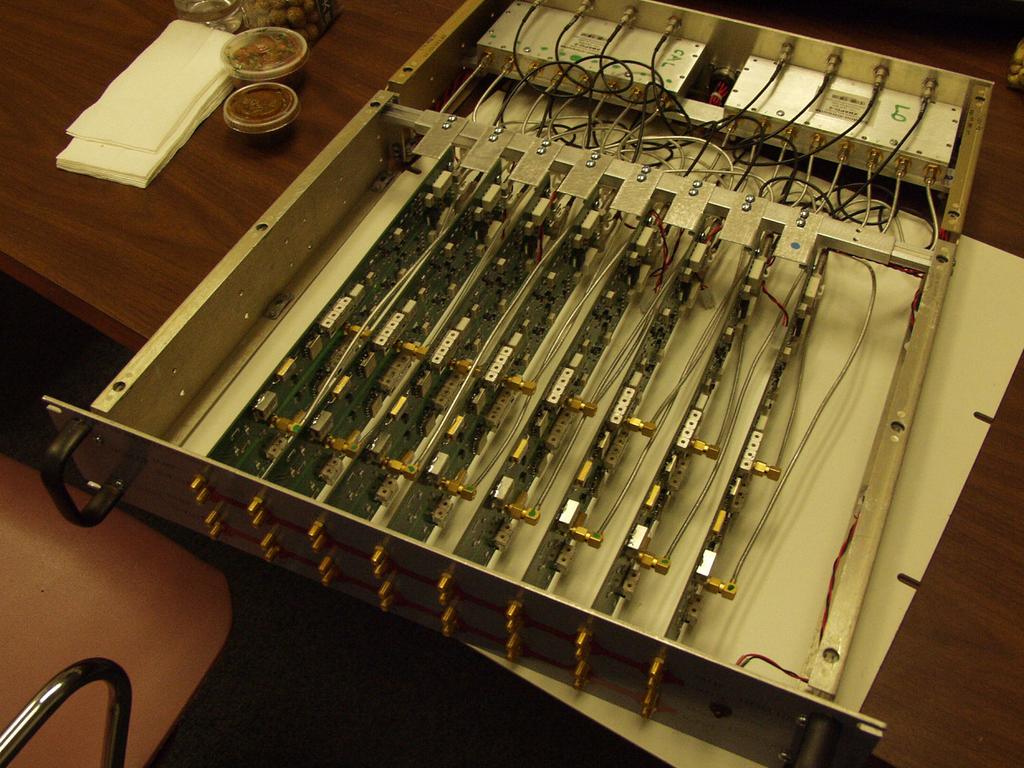
24 attn Coupler -14dB Coupler -14dB BP filter (wide-1) Limiter RF Amp 15dB attn BP filter (narrow) attn Mixer Sample out term RF processor card X8 term 1700MHz 20MHz BW 2 section Note: external 100 Ohm required 1:2 splitter 5 V regulator X2 channels 7.5V regulator 1700MHz 20MHz BW 4 section 1:2 splitter attn LO Amp 16dB Low Pas Filter RC to ground IF PreAmp 20dB 1:8 splitter 1:8 splitter 5 V regulator IF Amp 11dB RF processor Chassis X5 Anti-alias filter HOM signal in TE111-6: MHz 2 / structure Total 80 Timing Reference / Calibration Source: 8 output 8V in 1680MHz 13dBm LO Source 8 output 25MHz IF Digitizer VME crate controller DOOCS 24 SOFTWARE

25 HOM Downmix Board IF output amplifier Mixer Pre-amplifier Bandpass filters Input and sample out 25
26 26
27 27
28 28
29 New DAQ system plot (multi-bunch) Digitzer counts Time, seconds x
30 Multi-bunch operation New hardware can digitizer signals for the full length of the TTF bunch train. >1 millisecond. At each bunch passage, field amplitude from the bunch addes to the existing field amplitude. Fields from previous bunches decay at a predictable rate Only care about field after passage of previous bunch History does not matter. Can subtract (decayed) fields at time of previous bunch to find new contribution. Effective integration time ~1 microsecond (rather than ~10 currently used). Will reduce resolution, but still expect <10 microns. 30
31 HOM System Applications Real time BPM all cavities in TTF Expect single bunch resolution ~1 micron 3 micron demonstrated Measure each bunch in train to ~10 microns Multi-bunch measurement not yet demonstrated Need automated calibration and integration with DOOCS. HOM mode minimization feedback Should improve emittance Demonstrated for 2 cavities in one structure Should be possible to feedback to beam orbit which minimizes HOM power in full machine. Need to integrate with DESY feedback system Measure / monitor cavity alignment within structures Preliminary results suggest ~100 micron resolution Expect few micron results Work ongoing. 31
Using Higher Order Modes in the Superconducting TESLA Cavities for Diagnostics at DESY
 Using Higher Order Modes in the Superconducting TESLA Cavities for Diagnostics at FLASH @ DESY N. Baboi, DESY, Hamburg for the HOM team : S. Molloy 1, N. Baboi 2, N. Eddy 3, J. Frisch 1, L. Hendrickson
O. Napoly LC02, SLAC, Feb. 5, Higher Order Modes Measurements
 O. Napoly LC02, SLAC, Feb. 5, 2002 Higher Order Modes Measurements with Beam at the TTF Linac TTF Measurements A collective effort including most of Saclay, Orsay and DESY TTF physicists : S. Fartoukh,
Beam Diagnostics, Low Level RF and Feedback for Room Temperature FELs. Josef Frisch Pohang, March 14, 2011
 Beam Diagnostics, Low Level RF and Feedback for Room Temperature FELs Josef Frisch Pohang, March 14, 2011 Room Temperature / Superconducting Very different pulse structures RT: single bunch or short bursts
Precision RF Beam Position Monitors for Measuring Beam Position and Tilt Progress Report
 Precision RF Beam Position Monitors for Measuring Beam Position and Tilt Progress Report UC Berkeley Senior Personnel Yury G. Kolomensky Collaborating Institutions Stanford Linear Accelerator Center: Marc
Performance of the Prototype NLC RF Phase and Timing Distribution System *
 SLAC PUB 8458 June 2000 Performance of the Prototype NLC RF Phase and Timing Distribution System * Josef Frisch, David G. Brown, Eugene Cisneros Stanford Linear Accelerator Center, Stanford University,
PUBLICATION. HOM electronics and code to probe beam centring on 3.9 GHz cavities
 EuCARD-REP-2014-010 European Coordination for Accelerator Research and Development PUBLICATION HOM electronics and code to probe beam centring on 3.9 GHz cavities Zhang, P (DESY) 19 June 2014 The research
HIGHER ORDER MODES FOR BEAM DIAGNOSTICS IN THIRD HARMONIC 3.9 GHZ ACCELERATING MODULES *
 HIGHER ORDER MODES FOR BEAM DIAGNOSTICS IN THIRD HARMONIC 3.9 GHZ ACCELERATING MODULES * N. Baboi #, N. Eddy, T. Flisgen, H.-W. Glock, R. M. Jones, I. R. R. Shinton, and P. Zhang # # Deutsches Elektronen-Synchrotron
RF Locking of Femtosecond Lasers
 RF Locking of Femtosecond Lasers Josef Frisch, Karl Gumerlock, Justin May, Steve Smith SLAC Work supported by DOE contract DE-AC02-76SF00515 1 Overview FEIS 2013 talk discussed general laser locking concepts
ELECTRON BEAM DIAGNOSTICS AND FEEDBACK FOR THE LCLS-II*
 THB04 Proceedings of FEL2014, Basel, Switzerland ELECTRON BEAM DIAGNOSTICS AND FEEDBACK FOR THE LCLS-II* Josef Frisch, Paul Emma, Alan Fisher, Patrick Krejcik, Henrik Loos, Timothy Maxwell, Tor Raubenheimer,
Initial ARGUS Measurement Results
 Initial ARGUS Measurement Results Grant Hampson October 8, Introduction This report illustrates some initial measurement results from the new ARGUS system []. Its main focus is on simple measurements of
Available online at ScienceDirect. Physics Procedia 77 (2015 ) 42 49
 42 49") Available online at www.sciencedirect.com ScienceDirect Physics Procedia 77 (2015 ) 42 49 International Conference on Laser Applications at Accelerators, LA3NET 2015 Stability and resolution studies of
Available online at www.sciencedirect.com ScienceDirect Physics Procedia 77 (2015 ) 42 49 International Conference on Laser Applications at Accelerators, LA3NET 2015 Stability and resolution studies of
The Phased Array Feed Receiver System : Linearity, Cross coupling and Image Rejection
 The Phased Array Feed Receiver System : Linearity, Cross coupling and Image Rejection D. Anish Roshi 1,2, Robert Simon 1, Steve White 1, William Shillue 2, Richard J. Fisher 2 1 National Radio Astronomy
Physics Requirements Document Document Title: SCRF 1.3 GHz Cryomodule Document Number: LCLSII-4.1-PR-0146-R0 Page 1 of 7
 Document Number: LCLSII-4.1-PR-0146-R0 Page 1 of 7 Document Approval: Originator: Tor Raubenheimer, Physics Support Lead Date Approved Approver: Marc Ross, Cryogenic System Manager Approver: Jose Chan,
Beam Stabilization at
 Beam Stabilization at FERMI@EETTR S.Bassanese S.Cleva G.Gaio 1 FERMI s BPM system layout RD_KGxx o o o o Patch B o o o o Panel C o o o o D o o o o B C e - D BPM Trigger pulse RT Data Data Giga bit ETH
The HOM measurement of a TESLA cavity (Z84) for HOM-BPM and cavity alignment
 for HOM-BPM and cavity alignment") The HOM measurement of a TESLA cavity (Z84) for HOM-BPM and cavity alignment Ken.Watanabe:GUAS/AS (KEK) : presenter Hitoshi.Hayano, Shuichi.Noguchi, Eiji.Kako, Toshio.Shishido (KEK) Joint DESY and University
The HOM measurement of a TESLA cavity (Z84) for HOM-BPM and cavity alignment Ken.Watanabe:GUAS/AS (KEK) : presenter Hitoshi.Hayano, Shuichi.Noguchi, Eiji.Kako, Toshio.Shishido (KEK) Joint DESY and University
Next Linear Collider Beam Position Monitors
 NLC - The Project Beam Position Monitors Steve Smith SLAC October 23, 2002 What s novel, extreme, or challenging? Push resolution frontier Novel cavity BPM design for high resolution, stability Push well
A Prototype Wire Position Monitoring System
 LCLS-TN-05-27 A Prototype Wire Position Monitoring System Wei Wang and Zachary Wolf Metrology Department, SLAC 1. INTRODUCTION ¹ The Wire Position Monitoring System (WPM) will track changes in the transverse
A Synchrotron Phase Detector for the Fermilab Booster
 FERMILAB-TM-2234 A Synchrotron Phase Detector for the Fermilab Booster Xi Yang and Rene Padilla Fermi National Accelerator Laboratory Box 5, Batavia IL 651 Abstract A synchrotron phase detector is diagnostic
Title: New High Efficiency Intermodulation Cancellation Technique for Single Stage Amplifiers.
 Title: New High Efficiency Intermodulation Cancellation Technique for Single Stage Amplifiers. By: Ray Gutierrez Micronda LLC email: ray@micronda.com February 12, 2008. Introduction: This article provides
NanoBPM tests in the ATF extraction line
 NLC - The Next Linear Collider Project NanoBPM tests in the ATF extraction line Calibrate movers (tilters) and BPM s Understand and test dynamic range and resolution June 2003 Marc Ross What are the uses
Low-Level RF. S. Simrock, DESY. MAC mtg, May 05 Stefan Simrock DESY
 Low-Level RF S. Simrock, DESY Outline Scope of LLRF System Work Breakdown for XFEL LLRF Design for the VUV-FEL Cost, Personpower and Schedule RF Systems for XFEL RF Gun Injector 3rd harmonic cavity Main
Detection of Beam Induced Dipole-Mode Signals in the SLC S-Band Structures* Abstract
 -. SLAC-PUB-79 June 1997 Detection of Beam nduced Dipole-Mode Signals in the SLC S-Band Structures* M. Seidel, C. Adolphsen, R. Assmann, D.H. Whittum Stanford Linear Accelerator Center, Stanford University,
FONT Fast Feedback Systems
 Chapter 2 FONT Fast Feedback Systems The IP fast offset-correction feedback as described in the Reference Design Report for the ILC [11] is being developed under the heading of FONT (Feedback on Nanosecond
W-band vector network analyzer based on an audio lock-in amplifier * Abstract
 SLAC PUB 7884 July 1998 W-band vector network analyzer based on an audio lock-in amplifier * R. H. Siemann Stanford Linear Accelerator Center, Stanford University, Stanford CA 94309 Abstract The design
Cavity BPM With Dipole-Mode Selective Coupler
 Cavity BPM With Dipole-Mode Selective Coupler Zenghai Li Advanced Computations Department Stanford Linear Accelerator Center Presented at PAC23 Portland, Oregon. May 12-16, 23 Work supported by the U.S.
From Narrow to Wide Band Normalization for Orbit and Trajectory Measurements
 From Narrow to Wide Band Normalization for Orbit and Trajectory Measurements Daniel Cocq, Giuseppe Vismara CERN, Geneva, Switzerland Abstract. The beam orbit measurement (BOM) of the LEP collider makes
Performance Evaluation of the Upgraded BAMs at FLASH
 Performance Evaluation of the Upgraded BAMs at FLASH with a compact overview of the BAM, the interfacing systems & a short outlook for 2019. Marie K. Czwalinna On behalf of the Special Diagnostics team
Independent Measurement of Two Beams in an IP Feedback BPM (response to a question asked at LCWS05 )
") Independent Measurement of Two Beams in an IP Feedback BPM (response to a question asked at LCWS05 ) March 22, 2005 Steve Smith IP Feedback in 2-mr Crossing Scheme Both incoming and outgoing beams traverse
Independent Measurement of Two Beams in an IP Feedback BPM (response to a question asked at LCWS05 ) March 22, 2005 Steve Smith IP Feedback in 2-mr Crossing Scheme Both incoming and outgoing beams traverse
Feedback Requirements for SASE FELS. Henrik Loos, SLAC IPAC 2010, Kyoto, Japan
 Feedback Requirements for SASE FELS Henrik Loos, SLAC, Kyoto, Japan 1 1 Henrik Loos Outline Stability requirements for SASE FELs Diagnostics for beam parameters Transverse: Beam position monitors Longitudinal:
PXIe Contents SPECIFICATIONS. 14 GHz and 26.5 GHz Vector Signal Analyzer
 SPECIFICATIONS PXIe-5668 14 GHz and 26.5 GHz Vector Signal Analyzer These specifications apply to the PXIe-5668 (14 GHz) Vector Signal Analyzer and the PXIe-5668 (26.5 GHz) Vector Signal Analyzer with
Understanding Mixers Terms Defined, and Measuring Performance
 Understanding Mixers Terms Defined, and Measuring Performance Mixer Terms Defined Statistical Processing Applied to Mixers Today's stringent demands for precise electronic systems place a heavy burden
Diagnostics for Free Electron Lasers. Josef Frisch
 Diagnostics for Free Electron Lasers Josef Frisch Were you involved with LCLS lasing or did you only do the diagnostics? Can't construct a FEL with sufficient accuracy to allow it to lase when you turn
SC5307A/SC5308A 100 khz to 6 GHz RF Downconverter. Datasheet SignalCore, Inc.
 SC5307A/SC5308A 100 khz to 6 GHz RF Downconverter Datasheet 2017 SignalCore, Inc. support@signalcore.com P RODUCT S PECIFICATIONS Definition of Terms The following terms are used throughout this datasheet
Cavity BPMs for the NLC
 SLAC-PUB-9211 May 2002 Cavity BPMs for the NLC Ronald Johnson, Zenghai Li, Takashi Naito, Jeffrey Rifkin, Stephen Smith, and Vernon Smith Stanford Linear Accelerator Center, 2575 Sand Hill Road, Menlo
Experience with Insertion Device Photon Beam Position Monitors at the APS
 Experience with Insertion Device Photon Beam Position Monitors at the APS 27.6 meters (The APS has forty sectors - 1104 meters total circumference) Beam Position Monitors and Magnets in One Sector 18m
Trajectory Measurements in the DAΦNE Transfer Line using log Amplifier
 K K DAΦNE TECHNICAL NOTE INFN - LNF, Accelerator Division Frascati, April 6, 2004 Note: CD-14 Trajectory Measurements in the DAΦNE Transfer Line using log Amplifier A. Stella, O. Coiro Abstract The diagnostic
BluePhase 1000 PHASE NOISE TEST SYSTEM. Operations Manual
 BluePhase 1000 PHASE NOISE TEST SYSTEM Operations Manual WENZEL ASSOCIATES, INC. 2215 Kramer Lane Austin, TX 78758 USA 512-835-2038 fax 512-719-4086 http://www.wenzel.com e-mail: sales@wenzel.com Table
Reconfigurable 6 GHz RF Vector Signal Transceiver with 1 GHz Bandwidth
 CALIBRATION PROCEDURE PXIe-5840 Reconfigurable 6 GHz RF Vector Signal Transceiver with 1 GHz Bandwidth This document contains the verification procedures for the PXIe-5840 vector signal transceiver. Refer
Beam Position Monitor with HOM couplers
 Beam Position Monitor with HOM couplers Masaru Sawamura and Ryoji Nagai Japan Atomic Energy Research Institute (JAERI) 2-4 Shirakata-Shirane, Tokai, Ibaraki 319-1195, Japan Corresponding author: Masaru
Measurements 2: Network Analysis
 Measurements 2: Network Analysis Fritz Caspers CAS, Aarhus, June 2010 Contents Scalar network analysis Vector network analysis Early concepts Modern instrumentation Calibration methods Time domain (synthetic
HP Archive. This vintage Hewlett Packard document was preserved and distributed by www. hparchive.com Please visit us on the web!
 HP Archive This vintage Hewlett Packard document was preserved and distributed by www. hparchive.com Please visit us on the web! On-line curator: Glenn Robb This document is for FREE distribution only!
Utilizzo del Time Domain per misure EMI
 Utilizzo del Time Domain per misure EMI Roberto Sacchi Measurement Expert Manager - Europe 7 Giugno 2017 Compliance EMI receiver requirements (CISPR 16-1-1 ) range 9 khz - 18 GHz: A normal +/- 2 db absolute
New apparatus for precise synchronous phase shift measurements in storage rings 1
 New apparatus for precise synchronous phase shift measurements in storage rings 1 Boris Podobedov and Robert Siemann Stanford Linear Accelerator Center, Stanford University, Stanford, CA 94309 Measuring
Contents. CALIBRATION PROCEDURE NI PXIe GHz and 14 GHz RF Vector Signal Analyzer
 CALIBRATION PROCEDURE NI PXIe-5665 3.6 GHz and 14 GHz RF Vector Signal Analyzer This document contains the verification procedures for the National Instruments PXIe-5665 (NI 5665) RF vector signal analyzer
Advances in Antenna Measurement Instrumentation and Systems
 Advances in Antenna Measurement Instrumentation and Systems Steven R. Nichols, Roger Dygert, David Wayne MI Technologies Suwanee, Georgia, USA Abstract Since the early days of antenna pattern recorders,
A NEW GENERATION PROGRAMMABLE PHASE/AMPLITUDE MEASUREMENT RECEIVER
 GENERAL A NEW GENERATION PROGRAMMABLE PHASE/AMPLITUDE MEASUREMENT RECEIVER by Charles H. Currie Scientific-Atlanta, Inc. 3845 Pleasantdale Road Atlanta, Georgia 30340 A new generation programmable, phase-amplitude
CHAPTER 5 FINE-TUNING OF AN ECDL WITH AN INTRACAVITY LIQUID CRYSTAL ELEMENT
 CHAPTER 5 FINE-TUNING OF AN ECDL WITH AN INTRACAVITY LIQUID CRYSTAL ELEMENT In this chapter, the experimental results for fine-tuning of the laser wavelength with an intracavity liquid crystal element
Software Requirements Specification for LLRF Applications at FLASH Version 1.0 Prepared by Zheqiao Geng MSK, DESY Nov. 06, 2009
 Software Specification for LLRF Applications at FLASH Version 1.0 Prepared by Zheqiao Geng MSK, DESY Nov. 06, 2009 Copyright 2009 by Zheqiao Geng. Any change of this document should be agreed by the development
ECE 4670 Spring 2014 Lab 1 Linear System Characteristics
 ECE 4670 Spring 2014 Lab 1 Linear System Characteristics 1 Linear System Characteristics The first part of this experiment will serve as an introduction to the use of the spectrum analyzer in making absolute
TEST & MEASURING INSTRUMENTS. Analyzer. (4 Ports) 4 Ports
 4 Ports") TEST & MEASURING INSTRUMENTS Analyzer (4 Ports) 4 Ports Key Features Frequrncy Range : 100kHz ~ 8GHz, 16 Parameters support (S11 ~ S44) Measurement time per point : 100us per point Wide Output Power Range
TEST & MEASURING INSTRUMENTS Analyzer (4 Ports) 4 Ports Key Features Frequrncy Range : 100kHz ~ 8GHz, 16 Parameters support (S11 ~ S44) Measurement time per point : 100us per point Wide Output Power Range
Impedance 50 (75 connectors via adapters)
") VECTOR NETWORK ANALYZER PLANAR 304/1 DATA SHEET Frequency range: 300 khz to 3.2 GHz Measured parameters: S11, S21, S12, S22 Dynamic range of transmission measurement magnitude: 135 db Measurement time
VECTOR NETWORK ANALYZER PLANAR 304/1 DATA SHEET Frequency range: 300 khz to 3.2 GHz Measured parameters: S11, S21, S12, S22 Dynamic range of transmission measurement magnitude: 135 db Measurement time
Improvements of the LLRF system at FLASH. Mariusz Grecki, Waldemar Koprek and LLRF team
 Improvements of the LLRF system at FLASH Mariusz Grecki, Waldemar Koprek and LLRF team Agenda GUN linearization Adaptive feed-forward at ACC1 Beam load compensation at ACC1 Klystron nonlinearity compensation
LLRF Plans for SMTF. Ruben Carcagno (Fermilab) Nigel Lockyer (University of Pennsylvania) Thanks to DESY, PISA, KEK, Fermilab, SLAC Colleagues
 Nigel Lockyer (University of Pennsylvania) Thanks to DESY, PISA, KEK, Fermilab, SLAC Colleagues") LLRF Plans for SMTF Ruben Carcagno (Fermilab) Nigel Lockyer (University of Pennsylvania) Thanks to DESY, PISA, KEK, Fermilab, SLAC Colleagues Outline Near-term (< 1.5 years) SMTF LLRF plan Long-term (>
LLRF Plans for SMTF Ruben Carcagno (Fermilab) Nigel Lockyer (University of Pennsylvania) Thanks to DESY, PISA, KEK, Fermilab, SLAC Colleagues Outline Near-term (< 1.5 years) SMTF LLRF plan Long-term (>
Demonstration of exponential growth and saturation at VUV wavelengths at the TESLA Test Facility Free-Electron Laser. P. Castro for the TTF-FEL team
 Demonstration of exponential growth and saturation at VUV wavelengths at the TESLA Test Facility Free-Electron Laser P. Castro for the TTF-FEL team 100 nm 1 Å FEL radiation TESLA Test Facility at DESY
What s going on? FLASH Seminar Many People s work presented by D.Nölle, MDI,
 ; FLASH What s going on? Report on Diagnostic Activities at FLASH FLASH Seminar 11.11.08 Many People s work presented by D.Nölle, MDI, 9-2579 1 Topics FLASH BPMs Revision of the Stripline BPM Electronics
Windfreak Technologies SynthHD v1.4 Preliminary Data Sheet v0.2b
 Windfreak Technologies SynthHD v1.4 Preliminary Data Sheet v0.2b $1299.00US 54 MHz 13.6 GHz Dual Channel RF Signal Generator Features Open source Labveiw GUI software control via USB Run hardware functions
MEASURING HUM MODULATION USING MATRIX MODEL HD-500 HUM DEMODULATOR
 MEASURING HUM MODULATION USING MATRIX MODEL HD-500 HUM DEMODULATOR The SCTE defines hum modulation as, The amplitude distortion of a signal caused by the modulation of the signal by components of the power
HIGH POSITION RESOLUTION AND HIGH DYNAMIC RANGE STRIPLINE BEAM POSITION MONITOR (BPM) READOUT SYSTEM FOR THE KEKB INJECTOR LINAC TOWARDS THE SuperKEKB
 READOUT SYSTEM FOR THE KEKB INJECTOR LINAC TOWARDS THE SuperKEKB") HIGH POSITION RESOLUTION AND HIGH DYNAMIC RANGE STRIPLINE BEAM POSITION MONITOR (BPM) READOUT SYSTEM FOR THE KEKB INJECTOR LINAC TOWARDS THE SuperKEKB R. Ichimiya #, T. Suwada, M. Satoh, F. Miyahara, K.
HIGH POSITION RESOLUTION AND HIGH DYNAMIC RANGE STRIPLINE BEAM POSITION MONITOR (BPM) READOUT SYSTEM FOR THE KEKB INJECTOR LINAC TOWARDS THE SuperKEKB R. Ichimiya #, T. Suwada, M. Satoh, F. Miyahara, K.
Compact Series: S5065 & S5085 Vector Network Analyzers KEY FEATURES
 Compact Series: S5065 & S5085 Vector Network Analyzers KEY FEATURES Frequency range: 9 khz - 6.5 or 8.5 GHz Measured parameters: S11, S12, S21, S22 Wide output power adjustment range: -50 dbm to +5 dbm
Borut Baricevic. Libera LLRF. 17 September 2009
 Borut Baricevic Libera LLRF borut.baricevic@i-tech.si 17 September 2009 Outline Libera LLRF introduction Libera LLRF system topology Signal processing structure GUI and signal acquisition RF system diagnostics
Advances in RF and Microwave Measurement Technology
 1 Advances in RF and Microwave Measurement Technology Chi Xu Certified LabVIEW Architect Certified TestStand Architect New Demands in Modern RF and Microwave Test In semiconductor and wireless, technologies
PXA Configuration. Frequency range
 Keysight Technologies Making Wideband Measurements Using the Keysight PXA Signal Analyzer as a Down Converter with Infiniium Oscilloscopes and 89600 VSA Software Application Note Introduction Many applications
Spectrian Dual Mode Cellular Power Amplifier Model No.: SCLPA 800 CR FCC ID: I2ONTHX51AA
 A Class II Permissive Change - FCC Part 22 Type Acceptance Test Report for Spectrian Dual Mode Cellular Power Amplifier Model No.: SCLPA 800 CR FCC ID: I2ONTHX51AA Date of Report: May 26, 1999 Total No.
A COMPACT, AGILE, LOW-PHASE-NOISE FREQUENCY SOURCE WITH AM, FM AND PULSE MODULATION CAPABILITIES
 A COMPACT, AGILE, LOW-PHASE-NOISE FREQUENCY SOURCE WITH AM, FM AND PULSE MODULATION CAPABILITIES Alexander Chenakin Phase Matrix, Inc. 109 Bonaventura Drive San Jose, CA 95134, USA achenakin@phasematrix.com
SSB0260A Single Sideband Mixer GHz
 Single Sideband Mixer.2 6. GHz FEATURES LO/RF Frequency: Input IP3: Sideband Suppression: LO Leakage: LO Power: DC Power:.2 6. GHz +32 dbm -45 dbc (Typical) -5 dbm (Typical) -1 to +1 dbm +5V @ 5 ma DESCRIPTION
Dark Current Kicker Studies at FLASH
 Dark Current Kicker Studies at FLASH F. Obier, J. Wortmann, S. Schreiber, W. Decking, K. Flöttmann FLASH Seminar, DESY, 02 Feb 2010 History of the dark current kicker 2005 Vertical kicker was installed
A Modular Approach to Teaching Wireless Communications and Systems for ECET Students
 A Modular Approach to Teaching Wireless Communications and Systems for ECET Students James Z. Zhang, Robert Adams, Kenneth Burbank Department of Engineering and Technology Western Carolina University,
Techniques for Extending Real-Time Oscilloscope Bandwidth
 Techniques for Extending Real-Time Oscilloscope Bandwidth Over the past decade, data communication rates have increased by a factor well over 10x. Data rates that were once 1 Gb/sec and below are now routinely
Receiver Architecture
 Receiver Architecture Receiver basics Channel selection why not at RF? BPF first or LNA first? Direct digitization of RF signal Receiver architectures Sub-sampling receiver noise problem Heterodyne receiver
Contents. CALIBRATION PROCEDURE NI PXIe-5668R 14 GHz and 26.5 GHz Signal Analyzer
 CALIBRATION PROCEDURE NI PXIe-5668R 14 GHz and 26.5 GHz Signal Analyzer This document contains the verification procedures for the National Instruments PXIe-5668R (NI 5668R) vector signal analyzer (VSA)
DESCRIPTION OF THE OPERATION AND CALIBRATION OF THE MILLIMETER I/Q PHASE BRIDGE-INTERFEROMETER
 DESCRIPTION OF THE OPERATION AND CALIBRATION OF THE MILLIMETER I/Q PHASE BRIDGE-INTERFEROMETER Overview of Interferometer Operation The block diagram of the I/Q Phase Bridge-Interferometer is shown below
Cavity-type Beam Position Monitors for the SASE FEL at the TESLA Test Facility
 TESLA-FEL 2003-03 Cavity-type Beam Position Monitors for the SASE FEL at the TESLA Test Facility R. Lorenz 1, S. Sabah 2,H.J.Schreiber 3, H. Waldmann 3 1 Westdeutscher Rundfunk, 50600 Köln 2 VI-TELEFILTER
Addressing the Challenges of Wideband Radar Signal Generation and Analysis. Marco Vivarelli Digital Sales Specialist
 Addressing the Challenges of Wideband Radar Signal Generation and Analysis Marco Vivarelli Digital Sales Specialist Agenda Challenges of Wideband Signal Generation Challenges of Wideband Signal Analysis
RF/IF Terminology and Specs
 RF/IF Terminology and Specs Contributors: Brad Brannon John Greichen Leo McHugh Eamon Nash Eberhard Brunner 1 Terminology LNA - Low-Noise Amplifier. A specialized amplifier to boost the very small received
Design considerations for the RF phase reference distribution system for X-ray FEL and TESLA
 Design considerations for the RF phase reference distribution system for X-ray FEL and TESLA Krzysztof Czuba *a, Henning C. Weddig #b a Institute of Electronic Systems, Warsaw University of Technology,
HOM/LOM Coupler Study for the ILC Crab Cavity*
 SLAC-PUB-1249 April 27 HOM/LOM Coupler Study for the ILC Crab Cavity* L. Xiao, Z. Li, K. Ko, SLAC, Menlo Park, CA9425, U.S.A Abstract The FNAL 9-cell 3.9GHz deflecting mode cavity designed for the CKM
Advances in RF and Microwave Measurement Technology
 1 Advances in RF and Microwave Measurement Technology Rejwan Ali Marketing Engineer NI Africa and Oceania New Demands in Modern RF and Microwave Test In semiconductor and wireless, technologies such as
PXIe Contents CALIBRATION PROCEDURE. Reconfigurable 6 GHz RF Vector Signal Transceiver with 200 MHz Bandwidth
 IBRATION PROCEDURE PXIe-5646 Reconfigurable 6 GHz Vector Signal Transceiver with 200 MHz Bandwidth This document contains the verification and adjustment procedures for the PXIe-5646 vector signal transceiver.
Cavity Field Control - RF Field Controller. LLRF Lecture Part3.3 S. Simrock, Z. Geng DESY, Hamburg, Germany
 Cavity Field Control - RF Field Controller LLRF Lecture Part3.3 S. Simrock, Z. Geng DESY, Hamburg, Germany Content Introduction to the controller Control scheme selection In-phase and Quadrature (I/Q)
Linac Coherent Light Source (LCLS) Low Level RF Status LCLS FAC. October 30, 2007
 Low Level RF Status LCLS FAC. October 30, 2007") Linac Coherent Light Source (LCLS) Low Level RF Status LCLS Emma LCLS RF Gun, L0, and L1 Emma Dual Feed L0A L0B L0A 57MV 19MV/m L0B 72MV 24MV/m Off Axis Injector Vault Injector Transverse Accelerator 55cm
Linac Coherent Light Source (LCLS) Low Level RF Status LCLS Emma LCLS RF Gun, L0, and L1 Emma Dual Feed L0A L0B L0A 57MV 19MV/m L0B 72MV 24MV/m Off Axis Injector Vault Injector Transverse Accelerator 55cm
Performance of the TTF Photoinjector Laser System
 Performance of the TTF Photoinjector Laser System S. Schreiber, DESY Laser Issues for Electron Photoinjectors, October 23-25, 22, Stanford, California, USA & I. Will, A. Liero, W. Sandner, MBI Berlin Overview
USE OF MATLAB IN SIGNAL PROCESSING LABORATORY EXPERIMENTS
 USE OF MATLAB SIGNAL PROCESSG LABORATORY EXPERIMENTS R. Marsalek, A. Prokes, J. Prokopec Institute of Radio Electronics, Brno University of Technology Abstract: This paper describes the use of the MATLAB
R. J. Jones Optical Sciences OPTI 511L Fall 2017
 R. J. Jones Optical Sciences OPTI 511L Fall 2017 Semiconductor Lasers (2 weeks) Semiconductor (diode) lasers are by far the most widely used lasers today. Their small size and properties of the light output
A high resolution bunch arrival time monitor system for FLASH / XFEL
 A high resolution bunch arrival time monitor system for FLASH / XFEL K. Hacker, F. Löhl, F. Ludwig, K.H. Matthiesen, H. Schlarb, B. Schmidt, A. Winter October 24 th Principle of the arrival time detection
Progress in High Gradient Accelerator Research at MIT
 Progress in High Gradient Accelerator Research at MIT Presented by Richard Temkin MIT Physics and Plasma Science and Fusion Center May 23, 2007 MIT Accelerator Research Collaborators MIT Plasma Science
325 to 500 GHz Vector Network Analyzer System
 325 to 500 GHz Vector Network Analyzer System By Chuck Oleson, Tony Denning and Yuenie Lau OML, Inc. Abstract - This paper describes a novel and compact WR-02.2 millimeter wave frequency extension transmission/reflection
3250 Series Spectrum Analyzer
 The most important thing we build is trust ADVANCED ELECTRONIC SOLUTIONS AVIATION SERVICES COMMUNICATIONS AND CONNECTIVITY MISSION SYSTEMS 3250 Series Spectrum Analyzer > Agenda Introduction
STRETCHED-WIRE TECHNIQUES AND MEASUREMENTS FOR THE ALIGNMENT OF A 15GHz RF-BPM FOR CLIC
 STRETCHED-WIRE TECHNIQUES AND MEASUREMENTS FOR THE ALIGNMENT OF A 15GHz RF-BPM FOR CLIC S. Zorzetti, N. Galindo Munoz, M. Wendt, CERN, Geneva, Switzerland L. Fanucci, Universitá di Pisa, Pisa, Italy Abstract
Effects of Intensity and Position Modulation On Switched Electrode Electronics Beam Position Monitor Systems at Jefferson Lab*
 JLAB-ACT--9 Effects of Intensity and Position Modulation On Switched Electrode Electronics Beam Position Monitor Systems at Jefferson Lab* Tom Powers Thomas Jefferson National Accelerator Facility Newport
The behavior of the FastADC in time domain
 August 29, 2000 The behavior of the FastADC in time domain F. Tonisch 1. General remarks The 8-channel FastADC was developed for use with the readout electronic of the Waveguide Beam Position Monitors
Spectrum Analyzers 2680 Series Features & benefits
 Data Sheet Features & benefits n Frequency range: 9 khz to 2.1 or 3.2 GHz n High Sensitivity -161 dbm/hz displayed average noise level (DANL) n Low phase noise of -98 dbc/hz @ 10 khz offset n Low level
8853Q Spectrum Analyzer
 Increases Productivity by Providing a Complete Set of Spectrum Analysis Tests in One Instrument Intuitive User Interface Shortens Learning Curve Full-Featured, High-Performance, Remote Operation Automated
A 1.9GHz Single-Chip CMOS PHS Cellphone
 A 1.9GHz Single-Chip CMOS PHS Cellphone IEEE JSSC, Vol. 41, No.12, December 2006 William Si, Srenik Mehta, Hirad Samavati, Manolis Terrovitis, Michael Mack, Keith Onodera, Steve Jen, Susan Luschas, Justin
BANDPASS delta sigma ( ) modulators are used to digitize
 modulators are used to digitize") 680 IEEE TRANSACTIONS ON CIRCUITS AND SYSTEMS II: EXPRESS BRIEFS, VOL. 52, NO. 10, OCTOBER 2005 A Time-Delay Jitter-Insensitive Continuous-Time Bandpass 16 Modulator Architecture Anurag Pulincherry, Michael
680 IEEE TRANSACTIONS ON CIRCUITS AND SYSTEMS II: EXPRESS BRIEFS, VOL. 52, NO. 10, OCTOBER 2005 A Time-Delay Jitter-Insensitive Continuous-Time Bandpass 16 Modulator Architecture Anurag Pulincherry, Michael
PRACTICAL PROBLEMS INVOLVING PHASE NOISE MEASUREMENTS
 33rdAnnual Precise Time and Time Interval (P77 1)Meeting PRACTICAL PROBLEMS INVOLVING PHASE NOISE MEASUREMENTS Warren F. Walls Femtosecond Systems, Inc. 4894 Van Gordon St., Ste. 301-N Wheat Ridge, CO
Beam Test Results of High Q CBPM prototype for SXFEL *
 Beam Test Results of High Q CBPM prototype for SXFEL * Jian Chen ( 陈健 ),;) Yong-bin Leng ( 冷用斌 ) ;) Lu-yang Yu ( 俞路阳 ) Long-wei Lai ( 赖龙伟 ) Ren-xian Yuan ( 袁任贤 ) Shanghai Institute of Applied Physics,
FlexDDS-NG DUAL. Dual-Channel 400 MHz Agile Waveform Generator
 FlexDDS-NG DUAL Dual-Channel 400 MHz Agile Waveform Generator Excellent signal quality Rapid parameter changes Phase-continuous sweeps High speed analog modulation Wieserlabs UG www.wieserlabs.com FlexDDS-NG
Femtosecond Synchronization of Laser Systems for the LCLS
 Femtosecond Synchronization of Laser Systems for the LCLS, Lawrence Doolittle, Gang Huang, John W. Staples, Russell Wilcox (LBNL) John Arthur, Josef Frisch, William White (SLAC) 26 Aug 2010 FEL2010 1 Berkeley
A prototype S-band BPM system for the ILC energy spectrometer
 EUROTeV-Report-2008-072 A prototype S-band BPM system for the ILC energy spectrometer A. Lyapin, B. Maiheu, D. Attree, M. Wing, S. Boogert, G. Boorman, M. Slater, D. Ward January 12, 2009 Abstract This
Precision in Practice Achieving the best results with precision Digital Multimeter measurements
 Precision in Practice Achieving the best results with precision Digital Multimeter measurements Paul Roberts Fluke Precision Measurement Ltd. Abstract Digital multimeters are one of the most common measurement