Next Linear Collider Beam Position Monitors
|
|
|
- Lisa Parsons
- 5 years ago
- Views:
Transcription

1 NLC - The Project Beam Position Monitors Steve Smith SLAC October 23, 2002
2 What s novel, extreme, or challenging? Push resolution frontier Novel cavity BPM design for high resolution, stability Push well beyond NLC requirements Push bandwidth frontier Stripline BPM with very high bandwidth and resolution Pickup-less BPM HOM-Damped RF structures as position monitors Low propagation delay BPM Feedback within bunch-train crossing time (250 ns)
3 NLC Linac BPMs Quad BPM (QBPM) In every quadrupole (Quantity ~3000) Function: align quads to straight line Measures average position of bunch train Resolution required: 300 nm rms in a single shot Structure Position Monitor (SPM) Measure phase and amplitude of HOMs in accelerating cavities Minimize transverse wakefields Align each RF structure to the beam 22 k devices in two linacs Multi-Bunch BPM (MBBPM) Measure bunch-to-bunch transverse displacement Compensate residual wakefields Measure every bunch, 1.4 ns apart Requires high bandwidth (300 MHz), high resolution (300 nm) Line up entire bunch train by steering, compensating kickers
4 Other NLC BPMs Damping Ring Button pickups Rather conventional, like 3 rd generation light sources But higher readout rate (~MHz) Interaction Point Intra-Train Deflection Feedback Correct beam-beam mis-steering within time of train crossing Low propagation delay!
5 NLC QBPM Mainstream workhorse BPM In every quadrupole + Requires high resolution 300 nm Stability Single bunch to 180 bunches Stripline vs. cavity pickup? Cavity with novel coupler
6 QBPM Requirements Parameter Value Conditions Resolution 300 nm e - single bunch Position Stability 1 µm over 24 hours (!) Position Accuracy 200 µm With respect to the quad magnetic center Position Dynamic Range ±2 mm Charge Dynamic Range to e - per bunch Number of bunches Singlebunch - multibunch Bunch spacing 1.4 ns
7 Use Striplines for Q BPM? Electronics in tunnel enclosure Signal amplitudes in a ~30 MHz band around 714 MHz are demodulated and digitized Critical elements: Front-end hybrid Calibration signals Sampler / digitizer choices: Direct analog sampling chip + slow, high resolution ADC? IF downconversion + fast, high resolution ADC? Digital receiver algorithms for amplitude reconstruction bandpass filter digital downconversion low pass filter Position proportional to ratio of amplitude difference/sum
8 Can we achieve 300 nm resolution? Example: Final Focus Test Beam Position Monitor Achieves single bunch resolution of ~1.2 µm 9 x 10⁹ e- Algorithm: low pass filter, sample, digitize Bandwidth ~30 MHz Micron resolution is a few db above thermal noise floor NLC Q-BPM Beam pipe radius is factor of two smaller Process signal where it is big, i.e. 714 MHz instead of 32 MHz Noise floor is not an issue Must control systematics
9 What s wrong with striplines? Striplines are difficult to fit into limited quad ID Accuracy hard to establish Works on small differences of large numbers Position accuracy / stability requires precision of many elements Internal elements Stripline position Feedthroughs Termination External elements Cables Connections Processor
10 QBPMs Should be Cavities! Cavity BPM features: Signal is proportional to position Less common-mode subtraction than for strips Simpler geometry Accuracy of center better, more stable Pickup compact in Z dimension Cavity Drawbacks: Higher processing frequency Are wakefields tolerable?
11 Cavity BPM Pick a basic design and evaluate characteristics Pillbox cavity, for example Choose frequency, processing scheme Calculate Dimensions Sensitivity Noise figure budget Common-mode rejection Wake fields
12 Operating Frequency Sensitivity increases with frequency Size decreases with frequency Cable loss increases Cost of electronics increases Should be multiple of 714 MHz bunch spacing Possible operating frequencies: 2856 MHz (cavities are too big!) 5712 MHz (inexpensive commercial parts) GHz (share phase cavity with LLRF) GHz (integrate position cavities with RF structure) Example: GHz
13 Cavity BPM Parameters Parameter Value Comments Dipole frequency 11.4 GHz Monopole frequency 7.2 GHz Cavity Radius 16 mm Wall Q ~4000 Ignoring beam duct, etc Cavity coupling β = 3 Loaded Q 1000 Bandwidth 11 MHz Beam aperture radius 6 mm Sensitivity 7 mv/nc/µm (too much signal!) Bunch charge 0.7 x e - Per bunch Signal 1µm - 29 dbm Peak power Decay time 28 ns Required resolution σ = 200 nm Required Noise Figure 57 db For σ = 100 nm, thermal only Wakefield Kick 0.3 volt/pc/mm Long range Structure wakefield kick ~2 volt/pc/mm Per structure Short-range wakefield ~1/200 th of structure
14 Common Mode How much does monopole mode leak into dipole mode frequency? This creates an apparent beam centering offset. But processor looks only at dipole-mode frequency And uses odd-mode coupler to eliminate even-symmetry mode Comparison Voltage Ratio Ratio of monopole mode voltage to dipole mode voltage due to 1 mm beam offset, measured at outer radius of pillbox db Tail of monopole mode at dipole-mode frequency db Coupler rejection of monopole mode (-30dB) db So the common-mode leakage is negligible. (Even if the offset were tens of microns, its just a fixed offset)
15 BPM Cavity with TM 110 Couplers Dipole frequency: GHz Dipole mode: TM11 Coupling to waveguide: magnetic Beam x-offset couple to y port Port to coax Sensitivity: 1.6mV/nC/µm ( V/C/mm) Couple to dipole (TM11) only Does not couple to TM01 May need to damp TM01 OR, use stainless steel to lower Q Compact Low wakefield Zenghai Li
16 TM 110 Mode Coupler Port to coax Waveguide Beam pipe Magnetic coupling Zenghai Li

17

18 Waveguide Signal With Beam Excitation Zenghai Li
19 Cavity Dimensions Cavity sensitivity (?) df/db: MHz/µm df/da: MHz/µm df/dl: MHz/ µm Open port sharp iris r cav (mm) F 1 (with guide) MAFIA Omega Omega2 prediction F 1 (no guide) F 1 Zenghai Li
20 Azimuthal Misalignment 0.6mm Beam offset: 1.2mm TM01+TM11 in misaligned port Monopole modes sensitivity to displaced coupler: dx /dx ~ 2 in power ratio <0.01 monopole mode measured at dipole mode frequency We do get X-Y coupling X-Y Coupling Zenghai Li
21 Radial Misalignment 0.6mm Small x-y coupling Little fundamental mode Zenghai Li
22 Excellent Performance (in simulation) Relatively easy to fabricate Tolerant of errors Strong signal Good centering Small wakefields Build prototypes
23 Develop Cavity BPM Prototype Team: Ron Johnson, Zenghai Li, Takashi Naito, Jeff Rifkin, S. Smith Frequency: GHz Axially symmetric X-Y cavity TM 110 mode couplers designed by Z. Li Two couplers per mode for prototype cavity Integrate fundamental mode phase reference cavity in same block. Measure on bench In beam

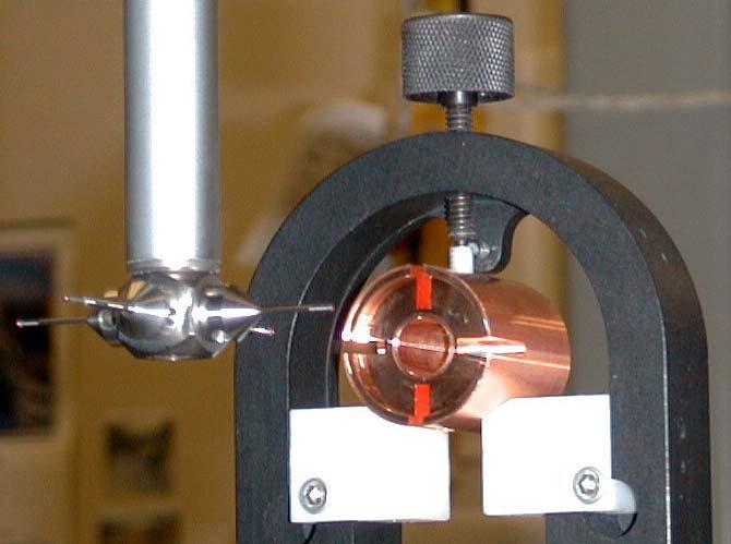
24 Cavity Body

25

26
27 Cavity Antenna Test
28 Antenna Test Phasor Response
29 Antenna Position
30 Antenna Test Residual Plot
31 Prototype Cavity Conclusions Excellent position response. Linear across null. Resolution is 230 nm rms. Resolution may be dominated by micrometer stage
32 Cavity Q-BPM Conclusions It is easy to get signal Resolution can be much better than required Signal is proportional to displacement Accurate centering is much easier than for striplines Common-mode is not a problem Wake fields are OK Requires microwave processing
33 Limits of Cavity BPM How far can you push cavity BPM technology? Way beyond NLC machine requirements! QBPM designed for low Q, low coupling Signal to thermal noise limit for resolution-optimized cavity σ = 0.1 nm for 11 GHz pillbox cavity and e - in a single bunch. Is a nanometer resolution BPM useful? Ground isn t stable at this level Active stabilization needed. But is available, and demands beam tests! Passive isolation Geophone feedback Optical anchor (interferometer)
34 Nanometer Resolution BPMs Push cavity BPM technology to its limits Push existing C-band cavities to 1nm at ATF (KEK) Harder at 5.7 GHz than 11.4 GHz!
35 Bunch Tiltmeter NLC alignment tolerances and diagnostic requirements derive from wakefield emittance dilution. Transverse wakefields cause head-tail displacement Can we measure this directly, rather than by position of the mean charge of the bunch? Observation at ASSET: BPM Cavity power vs. beam position has minimum which depends on bunch tilt Tilt signal is in quadrature with position signal
36 Response of BPM to Tilted Bunch Centered in Cavity q Treat as pair of macroparticles: q/ 2 δ/2 δ/ 2 σ t q/ 2 q δ σ t q δ σ t aδq ωσ t V ( t) = a sinω( t ) a sinω( t + ) = cosωt sin
37 Tilted bunch Point charge offset by δ Centered, extended bunch tilted at slope δ/σ t Tilt signal is in quadrature to displacement The amplitude due to a tilt of δ/σ is down by a factor of: with respect to that of a displacement of δ (~bunch length / Cavity Period ) V y V t V ( t) = aqδ sin( ωt) aδq ωσ t ( t) = cosωt sin 2 2 t V y ωσ t πσ = = t 4 2T
38 Example Bunch length σ t = 200 µm/c = 0.67 ps Tilt tolerance d = 200 nm Cavity Frequency F = GHz Ratio of tilt to position sensitivity ½πfσ t = A bunch tilt of 200 nm / 200 µm yields as much signal as a beam offset of * 200 nm = 2.4nm Need BPM resolution of ~ 2 nm to measure this tilt Challenging! Getting resolution Separating tilt from position Use higher cavity frequency?
39 Position-Tilt Discrimination Phase-sensitive detection Position jitter or dithering measures phase of position signal Quadrature part of signal is tilt + background One phase of residual common mode RF interference/leakage The higher the frequency the better! Tiltmeter also sensitive to beam tilt / cavity tilt
40 Tiltmeter R&D Plans Test with C-Band cavity BPMs at ATF (KEK) First test done, cavity tilt dominates Put more cavities on goniometers

41 NLC RF Structure Use dipole modes in accelerating cavities to measure beam position. Align each RF structure to the beam Minimize transverse wakefields
42 Transverse Modes in Structure Transverse modes contain position information Modes associated with z position along structure. Tunable receiver can measure position along structure.
43 Structure Position Monitor Damped, Detuned RF structures (DDS) Damped: 4 HOM manifolds conduct transverse modes to load Detuned: HOM mode frequency depends on z-position in structure Two of the manifolds, have coax couplers which sample a fraction of the HOM power BPM measures amplitude and phase of transverse modes at load. Tune over GHz to see position from one end to the other. Use to align structures to beam.
44 SPM Receiver Tunable across dipole band Frequency selects z-coordinate of position measurement Receiver is phase-sensitive : Reduces noise Provides sign of offset. Beam phase reference provided by nearby cavity BPM needs phase accuracy of only ± 90 in order to extract the sign of the beam direction. Noise performance improves slightly with better phase reference Low-level RF system requires beam phase accuracy of a few degrees, which will be from the same source.
45 SPM Requirements Parameter Requirement Comments Quantity ~22,000 X,Y BPM s ~ 700 X,Y BPM s in X-band linacs in S-band linacs Resolution rms = 5 µm or 10% of beam position, whichever is greater single bunch of e -, for at least one mode near each end Position Dynamic Range R < 3 mm R < 0.5 mm single bunch or low current multibunch full current, multibunch Stability of Center <1 µm over 30 minutes Survival at 3 Must not damage receiver mm radius
46 Cell Offset vs. HOM Minimum
47 Structure Position Monitor Looks promising Have not developed even prototype electronics R&D needed on integrated RF module Large system, it must be: high performance reliable cheap
48 Multi-Bunch BPMs Bandwidth frontier (300 MHz bandwidth) Stripline pickups Report position of every bunch in bunch train Used to program broadband kickers to straighten out bunch train Parameter Value Conditions & Comments Resolution 300 nm rms At 0.6 x e - / bunch for bunch-bunch diplacement frequencies below 300 MHz Position Range ±2 mm Bunch spacing 2.8 ns or 1.4 ns Number of Bunches 1.4 ns Beam current dynamic range Number of BPMs to Particles / bunch 278
49 Model Multi-Bunch BPM Electronics Preprocess using matched filters, sum-difference hybrids Digitize waveform from stripline using either fast ADC s Sampling chip followed by slow ADC Deconvolute bunch-bunch response from multibunch using impulse response measured with single bunch R&D Demonstrate concept Develop switched capacitor analog memory chip Save cost space power
50 R&D Sampling Chip development In house Ohio State Proofs of Principle Measuring bunchtrains at KEK-ATF Digital receiver algorithm for Q-BPM, DR-BPM test in linac, PEP-II Test promising parts on eval boards Prototype

51 Multi-Bunch BPM Block Diagram Front End Box Tek 3054 BPM Front End Box

52 ATF Bunch Current
53 Damping Ring BPMs Button pickups in rings Cables to holes in tunnel wall Quantity 486 total in three rings Two main damping rings & e + Pre-damping ring Process signals in digital receiver Measure amplitude in ~10 MHz bandwidth about 714 MHz Differences from PEP BPM: Slightly higher resolution smaller signal smaller beam duct High peak readout rate (once per turn ~MHz)
54 DR-BPM Requirements Parameter Requirement Conditions & Comments Duct radius 17.5 mm in arcs up to 31 mm in straights PEP-II is 33 mm in arcs, 45 mm in straights Button Diameter 8 mm PEP-II is 15 mm Button Transfer Impedance ~ MHz Time resolution Average over 20 bunches Can we average over train? Measurement Rate Onboard processing Resolution for train of > 20 bunches Resolution for single bunch Read every turn (1.4 MHz in predr) Multi-turn logging Multi-turn averaging Sine fit to turn-by-turn data 500mA σ 1 1+ x µm Itrain σ Single µm 2 PEP-II ADC runs at 136 khz Several 14-bit 65 MHz 5 For Q b > electrons Initial accuracy TBD Before beam-based-alignment Stability wrt time 1µm 10µm Stability wrt fill pattern <10µm shift, single bunch to full train over a few hours over 24 hours
55 Intra-pulse Feedback Ground Motion at NLC IP Differential ground motion between opposing final lenses may be comparable to the beam sizes Several solutions possible: Optical anchor stabilization Inertial stabilization (geophone feedback) Pulse-to-pulse beam-beam alignment feedback Can we use beam-beam deflection within the crossing time a single bunch train?

56 NLC Interaction Point Parameters
57 Beam-Beam Parameters Parameter Value Comments σ y 2.65 nm (!) σ x 245 nm σ z 110 µm Disruption Parameter Deflection slope Displacement slope µradian / nm 100 µm/nm At origin At BPM
58 Intra-pulse Feedback Fix interaction point jitter within the crossing time of a single bunch train (266 ns) BPM measures beam-beam deflection on outgoing beam Fast (few ns rise time) Precise (~micron resolution << 1nm beam offset resolution) Close (~4 meters from IP) Kicker steers incoming beam Close to IP (~4 meters) Close to BPM (minimal cable delay) Fast rise-time amplifier Feedback algorithm is complicated by: round-trip propagation delay to interaction point in the feedback loop. transfer function non-linearity
59 Intra-Pulse Feedback Kicker Amp IP Round + Trip Delay BPM Processor BPM
60 Beam Position Monitor Stripline BPM 50 Ohm 6 mm radius 10 cm long 7% angular coverage 4 m from IP Process at 714 MHz Downconvert to baseband need to phase BPM Wideband: 200 MHz at baseband Analog response with < 3ns propagation delay (plus cable lengths)
61 Fast BPM Processor Timing System 714 MHz Phase Reference Top Stripline Normalize BPM to Bunch Charge RF Hybrid Bandpass filter MIXER Lowpass filter Programable Attenuator Kicker Drive Bottom Stipline Bessel 4-pole 714 MHz 360 MHz BW Bessel 3-pole 200 MHz MPS Network (Bunch Charge) Fast BPM Processor Block Diagram
 and BPM analog output")
62 Simulated BPM Processor Signals BPM Pickup (blue) Bandpass filter (green) and BPM analog output (red)

63 Prototype Hardware Position monitor processor looks like the simulation
64 Stripline Kicker Baseband Kicker Parallel plate approximation Θ = 2eVL/pwc (half the kick comes from electric field, half from magnetic) 2 strips 75 cm long 50 Ohm / strip 6 mm half-gap 4 m from IP Deflection angle Θ = evl/pwc = 1 nr/volt Displacement at IP d = 4 nm/volt Voltage required to move beam 1 σ (3 nm) 0.75 volts (10 mw) 100 nm correction requires 12.5 Watts drive per strip Drive amp needs bandwidth from 100 khz to 100 MHz
65 Capture Transient Capture transient from 2 σ initial offset
66 Limits to Beam-Beam Feedback Must close loop fast Propagation delays are painful Beam-Beam deflection response is non-linear slope flattens within 1 σ Linear feedback converges too slowly beyond ~ 10 σ to recover most of lost luminosity. Should be able to fix misalignments of 100 nm with modest kicker amplifiers. Amplifier power goes like square of misalignment.
67 Non-linear Response Challenges Feedback Beam-beam deflection non-linearity limits: Limits useful (timely) range of convergence Limits stability in collision
68 Non-linear Response Challenges Feedback Optimize gain for small initial offset: Then convergence is poor from far out: Set gain for good convergence, then high gain at origin causes oscillation when near center:
69 Linearize Feedback Can we compensate non-linearity? Fast? Bandwidth propagation delay Accurately? Yes! Add compensation amplifier Op-amp Diodes to introduce desired non-linearity. Bias adjust (knee or breakpoint)
70 Schematic
71 Measured Transfer Function
72 Large Signal Waveform 1 V step Full BW Settles to DC response in several ns
73 Simulink Model 10 mv step 150 MHz BW
74 Non-Linear Feedback Simulation Compensated Uncompensated Full luminosity recovered in one round-trip time for 10 σ initial offset.
75 Linearizer Conclusions Simple op-amp based non-linear amp is sufficient to improve: Stability Convergence speed capture range Programmable linearity compensation Low propagation delay: ~ 1 ns High bandwidth > 200 MHz Sufficient to achieve: Single round-trip convergence to < 1 σ from 10 σ initial offset. Two-cycle convergence to < 0.1 σ from 10 σ initial offset. Limited by dynamic range of present op-amp, not by accuracy of compensation Fix with another amplifier or tune diode bias Breadboard prototype slightly peaky for small signals Likely to be fixed with chip diodes in real layout Ideally would make large signal response as peaky as small-signal response (to compensate kicker fill time)
76 Intra-Pulse Feedback Kicker Amp IP Round + Trip Delay BPM Processor BPM
77 Intra-Pulse Feedback (with Beam-Beam Scan & Diagnostics) Kicker Amp IP Round + Trip Delay BPM Processor BPM Beam-Beam Scan & Diagnostics Ramp Digitizer
78 Beam-Beam Scan Beam bunches at IP: blue points BPM analog response: green line
79 Conclusions Q BPMs Need cavity BPMs Accuracy Stability Compact Damping Ring BPM Small evolution of current practice Structure Position Monitors Electronically more like Direct Sattelite TV receiver New to us, but similar objects are commercially available Multi-Bunch BPMs High resolution High bandwidth Beyond state of the art Achievable based on reasonable extrapolation of technology
80 Extensions Beyond NLC machine requirements: Bunch tiltmeter Nanometer resolution BPM s
Cavity BPM With Dipole-Mode Selective Coupler
 Cavity BPM With Dipole-Mode Selective Coupler Zenghai Li Advanced Computations Department Stanford Linear Accelerator Center Presented at PAC23 Portland, Oregon. May 12-16, 23 Work supported by the U.S.
NanoBPM tests in the ATF extraction line
 NLC - The Next Linear Collider Project NanoBPM tests in the ATF extraction line Calibrate movers (tilters) and BPM s Understand and test dynamic range and resolution June 2003 Marc Ross What are the uses
Cavity BPMs for the NLC
 SLAC-PUB-9211 May 2002 Cavity BPMs for the NLC Ronald Johnson, Zenghai Li, Takashi Naito, Jeffrey Rifkin, Stephen Smith, and Vernon Smith Stanford Linear Accelerator Center, 2575 Sand Hill Road, Menlo
Independent Measurement of Two Beams in an IP Feedback BPM (response to a question asked at LCWS05 )
") Independent Measurement of Two Beams in an IP Feedback BPM (response to a question asked at LCWS05 ) March 22, 2005 Steve Smith IP Feedback in 2-mr Crossing Scheme Both incoming and outgoing beams traverse
Independent Measurement of Two Beams in an IP Feedback BPM (response to a question asked at LCWS05 ) March 22, 2005 Steve Smith IP Feedback in 2-mr Crossing Scheme Both incoming and outgoing beams traverse
Precision RF Beam Position Monitors for Measuring Beam Position and Tilt Progress Report
 Precision RF Beam Position Monitors for Measuring Beam Position and Tilt Progress Report UC Berkeley Senior Personnel Yury G. Kolomensky Collaborating Institutions Stanford Linear Accelerator Center: Marc
Beam Diagnostics, Low Level RF and Feedback for Room Temperature FELs. Josef Frisch Pohang, March 14, 2011
 Beam Diagnostics, Low Level RF and Feedback for Room Temperature FELs Josef Frisch Pohang, March 14, 2011 Room Temperature / Superconducting Very different pulse structures RT: single bunch or short bursts
HOM Based Diagnostics at the TTF
 HOM Based Diagnostics at the TTF Nov 14, 2005 Josef Frisch, Nicoleta Baboi, Linda Hendrickson, Olaf Hensler, Douglas McCormick, Justin May, Olivier Napoly, Rita Paparella, Marc Ross, Claire Simon, Tonee
Physics Requirements Document Document Title: SCRF 1.3 GHz Cryomodule Document Number: LCLSII-4.1-PR-0146-R0 Page 1 of 7
 Document Number: LCLSII-4.1-PR-0146-R0 Page 1 of 7 Document Approval: Originator: Tor Raubenheimer, Physics Support Lead Date Approved Approver: Marc Ross, Cryogenic System Manager Approver: Jose Chan,
FONT Fast Feedback Systems
 Chapter 2 FONT Fast Feedback Systems The IP fast offset-correction feedback as described in the Reference Design Report for the ILC [11] is being developed under the heading of FONT (Feedback on Nanosecond
Design of S-band re-entrant cavity BPM
 Nuclear Science and Techniques 20 (2009) 133 139 Design of S-band re-entrant cavity BPM LUO Qing SUN Baogen * HE Duohui National Synchrotron Radiation Laboratory, School of Nuclear Science and Technology,
Performance of the Prototype NLC RF Phase and Timing Distribution System *
 SLAC PUB 8458 June 2000 Performance of the Prototype NLC RF Phase and Timing Distribution System * Josef Frisch, David G. Brown, Eugene Cisneros Stanford Linear Accelerator Center, Stanford University,
A prototype S-band BPM system for the ILC energy spectrometer
 EUROTeV-Report-2008-072 A prototype S-band BPM system for the ILC energy spectrometer A. Lyapin, B. Maiheu, D. Attree, M. Wing, S. Boogert, G. Boorman, M. Slater, D. Ward January 12, 2009 Abstract This
O. Napoly LC02, SLAC, Feb. 5, Higher Order Modes Measurements
 O. Napoly LC02, SLAC, Feb. 5, 2002 Higher Order Modes Measurements with Beam at the TTF Linac TTF Measurements A collective effort including most of Saclay, Orsay and DESY TTF physicists : S. Fartoukh,
CERN EUROPEAN ORGANIZATION FOR NUCLEAR RESEARCH INVESTIGATION OF A RIDGE-LOADED WAVEGUIDE STRUCTURE FOR CLIC X-BAND CRAB CAVITY
 CERN EUROPEAN ORGANIZATION FOR NUCLEAR RESEARCH CLIC Note 1003 INVESTIGATION OF A RIDGE-LOADED WAVEGUIDE STRUCTURE FOR CLIC X-BAND CRAB CAVITY V.F. Khan, R. Calaga and A. Grudiev CERN, Geneva, Switzerland.
Low-Level RF. S. Simrock, DESY. MAC mtg, May 05 Stefan Simrock DESY
 Low-Level RF S. Simrock, DESY Outline Scope of LLRF System Work Breakdown for XFEL LLRF Design for the VUV-FEL Cost, Personpower and Schedule RF Systems for XFEL RF Gun Injector 3rd harmonic cavity Main
Lawrence Berkeley Laboratory UNIVERSITY OF CALIFORNIA
 d e Lawrence Berkeley Laboratory UNIVERSITY OF CALIFORNIA Accelerator & Fusion Research Division I # RECEIVED Presented at the International Workshop on Collective Effects and Impedance for B-Factories,
ATF2 Project at KEK. T. Tauchi, KEK at Orsay 17 June, 2005
 ATF2 Project at KEK T. Tauchi, KEK at Orsay 17 June, 2005 IP Final Goal Ensure collisions between nanometer beams; i.e. luminosity for ILC experiment Reduction of Risk at ILC FACILITY construction, first
LHC TRANSVERSE FEEDBACK SYSTEM: FIRST RESULTS OF COMMISSIONING. V.M. Zhabitsky XXI Russian Particle Accelerator Conference
 LHC TRANSVERSE FEEDBACK SYSTEM: FIRST RESULTS OF COMMISSIONING V.M. Zhabitsky XXI Russian Particle Accelerator Conference 28.09-03.10.2008, Zvenigorod LHC Transverse Feedback System: First Results of Commissioning
FAST RF KICKER DESIGN
 FAST RF KICKER DESIGN David Alesini LNF-INFN, Frascati, Rome, Italy ICFA Mini-Workshop on Deflecting/Crabbing Cavity Applications in Accelerators, Shanghai, April 23-25, 2008 FAST STRIPLINE INJECTION KICKERS
RF Design of Normal Conducting Deflecting Cavity
 RF Design of Normal Conducting Deflecting Cavity Valery Dolgashev (SLAC), Geoff Waldschmidt, Ali Nassiri (Argonne National Laboratory, Advanced Photon Source) 48th ICFA Advanced Beam Dynamics Workshop
Fast Intra-Train Feedback Systems for a Future Linear Collider
 Fast Intra-Train Feedback Systems for a Future Linear Collider University of Oxford: Phil Burrows, Glen White, Simon Jolly, Colin Perry, Gavin Neesom DESY: Nick Walker SLAC: Joe Frisch, Steve Smith, Thomas
ELECTRON BEAM DIAGNOSTICS AND FEEDBACK FOR THE LCLS-II*
 THB04 Proceedings of FEL2014, Basel, Switzerland ELECTRON BEAM DIAGNOSTICS AND FEEDBACK FOR THE LCLS-II* Josef Frisch, Paul Emma, Alan Fisher, Patrick Krejcik, Henrik Loos, Timothy Maxwell, Tor Raubenheimer,
A high resolution bunch arrival time monitor system for FLASH / XFEL
 A high resolution bunch arrival time monitor system for FLASH / XFEL K. Hacker, F. Löhl, F. Ludwig, K.H. Matthiesen, H. Schlarb, B. Schmidt, A. Winter October 24 th Principle of the arrival time detection
GHZ STRIPLINE TRANSVERSAL FILTER FOR SUB-PICOSECOND BUNCH TIMING MEASUREMENTS*
 Proceedings of BIW1, Santa Fe, New Mexico, US TUPSM8 11.424 GHZ STRIPLINE TRANSVERSAL FILTER FOR SUB-PICOSECOND BUNCH TIMING MEASUREMENTS* D. Van Winkle, A. Young, J. D. Fox SLAC National Accelerator Laboratory,
Bunch-by-Bunch Broadband Feedback for the ESRF
 Bunch-by-Bunch Broadband Feedback for the ESRF ESLS RF meeting / Aarhus 21-09-2005 J. Jacob, E. Plouviez, J.-M. Koch, G. Naylor, V. Serrière Goal: Active damping of longitudinal and transverse multibunch
CERN EUROPEAN ORGANIZATION FOR NUCLEAR RESEARCH DESIGN OF PHASE FEED FORWARD SYSTEM IN CTF3 AND PERFORMANCE OF FAST BEAM PHASE MONITORS
 CERN EUROPEAN ORGANIZATION FOR NUCLEAR RESEARCH CLIC Note 1007 DESIGN OF PHASE FEED FORWARD SYSTEM IN CTF3 AND PERFORMANCE OF FAST BEAM PHASE MONITORS P.K. Skowro nski, A. Andersson (CERN, Geneva), A.
Using Higher Order Modes in the Superconducting TESLA Cavities for Diagnostics at DESY
 Using Higher Order Modes in the Superconducting TESLA Cavities for Diagnostics at FLASH @ DESY N. Baboi, DESY, Hamburg for the HOM team : S. Molloy 1, N. Baboi 2, N. Eddy 3, J. Frisch 1, L. Hendrickson
OVERVIEW OF RECENT TRENDS AND DEVELOPMENTS FOR BPM SYSTEMS
 OVERVIEW OF RECENT TRENDS AND DEVELOPMENTS FOR BPM SYSTEMS Manfred Wendt Fermilab Assembled with great help of the colleagues from the beam instrumentation community! Contents Introduction BPM Pickup Broadband
BPM requirements for energy spectrometry
 BPM requirements for energy spectrometry Stewart T. Boogert University College London UK (UCL, Cambridge) SB, Alexey Lyapin, David Miller, Mark Slater, David Ward, Mathew Wing US (SLAC, LLNL, LBNL, Oregon,
Advanced Photon Source Monopulse rf Beam Position Monitor Front-End Upgrade*
 Advanced Phon Source Monopulse rf Beam Position Monir Front-End Upgrade* Robert M. Lill and Glenn A. Decker Advanced Phon Source, Argonne National Laborary 9700 South Cass Avenue, Argonne, Illinois 60439
MEASURES TO REDUCE THE IMPEDANCE OF PARASITIC RESONANT MODES IN THE DAΦNE VACUUM CHAMBER
 Frascati Physics Series Vol. X (1998), pp. 371-378 14 th Advanced ICFA Beam Dynamics Workshop, Frascati, Oct. 20-25, 1997 MEASURES TO REDUCE THE IMPEDANCE OF PARASITIC RESONANT MODES IN THE DAΦNE VACUUM
International Technology Recommendation Panel. X-Band Linear Collider Path to the Future. RF System Overview. Chris Adolphsen
 International Technology Recommendation Panel X-Band Linear Collider Path to the Future RF System Overview Chris Adolphsen Stanford Linear Accelerator Center April 26-27, 2004 Delivering the Beam Energy
Beam BreakUp at Daresbury. Emma Wooldridge ASTeC
 Beam BreakUp at Daresbury Emma Wooldridge ASTeC Outline The causes of Beam Breakup (BBU) Types of BBU Why investigate BBU? Possible solutions Causes of BBU There are four main causes. Interaction with
Numerical Simulation of &hepep-i1 Beam Position Monitor*
 SLACPUB957006 September 1995 Numerical Simulation of &hepepi1 Beam Position Monitor* N. Kurita D. Martin C.K. Ng S. Smith Stanford Linear Accelerator Center Stanford University Stanford CA 94309USA and
Detection of Beam Induced Dipole-Mode Signals in the SLC S-Band Structures* Abstract
 -. SLAC-PUB-79 June 1997 Detection of Beam nduced Dipole-Mode Signals in the SLC S-Band Structures* M. Seidel, C. Adolphsen, R. Assmann, D.H. Whittum Stanford Linear Accelerator Center, Stanford University,
SIGNAL ELECTRIC FIELD MAGNETIC FIELD # 1 (#2) #3 (# 4) WAVEGUIDE VACUUM CHAMBER BEAM PIPE VACUUM CHAMBER
 #3 (# 4) WAVEGUIDE VACUUM CHAMBER BEAM PIPE VACUUM CHAMBER") New Microwave Beam Position Monitors for the TESLA Test Facility FEL T. Kamps and R. Lorenz DESY Zeuthen, Platanenallee 6, D-15738 Zeuthen Abstract. Beam-based alignment is essential for the operation
New Microwave Beam Position Monitors for the TESLA Test Facility FEL T. Kamps and R. Lorenz DESY Zeuthen, Platanenallee 6, D-15738 Zeuthen Abstract. Beam-based alignment is essential for the operation
A Synchrotron Phase Detector for the Fermilab Booster
 FERMILAB-TM-2234 A Synchrotron Phase Detector for the Fermilab Booster Xi Yang and Rene Padilla Fermi National Accelerator Laboratory Box 5, Batavia IL 651 Abstract A synchrotron phase detector is diagnostic
HIGH POSITION RESOLUTION AND HIGH DYNAMIC RANGE STRIPLINE BEAM POSITION MONITOR (BPM) READOUT SYSTEM FOR THE KEKB INJECTOR LINAC TOWARDS THE SuperKEKB
 READOUT SYSTEM FOR THE KEKB INJECTOR LINAC TOWARDS THE SuperKEKB") HIGH POSITION RESOLUTION AND HIGH DYNAMIC RANGE STRIPLINE BEAM POSITION MONITOR (BPM) READOUT SYSTEM FOR THE KEKB INJECTOR LINAC TOWARDS THE SuperKEKB R. Ichimiya #, T. Suwada, M. Satoh, F. Miyahara, K.
HIGH POSITION RESOLUTION AND HIGH DYNAMIC RANGE STRIPLINE BEAM POSITION MONITOR (BPM) READOUT SYSTEM FOR THE KEKB INJECTOR LINAC TOWARDS THE SuperKEKB R. Ichimiya #, T. Suwada, M. Satoh, F. Miyahara, K.
HOM/LOM Coupler Study for the ILC Crab Cavity*
 SLAC-PUB-1249 April 27 HOM/LOM Coupler Study for the ILC Crab Cavity* L. Xiao, Z. Li, K. Ko, SLAC, Menlo Park, CA9425, U.S.A Abstract The FNAL 9-cell 3.9GHz deflecting mode cavity designed for the CKM
Cavity-type Beam Position Monitors for the SASE FEL at the TESLA Test Facility
 TESLA-FEL 2003-03 Cavity-type Beam Position Monitors for the SASE FEL at the TESLA Test Facility R. Lorenz 1, S. Sabah 2,H.J.Schreiber 3, H. Waldmann 3 1 Westdeutscher Rundfunk, 50600 Köln 2 VI-TELEFILTER
(i) Determine the admittance parameters of the network of Fig 1 (f) and draw its - equivalent circuit.
 Determine the admittance parameters of the network of Fig 1 (f) and draw its - equivalent circuit.") I.E.S-(Conv.)-1995 ELECTRONICS AND TELECOMMUNICATION ENGINEERING PAPER - I Some useful data: Electron charge: 1.6 10 19 Coulomb Free space permeability: 4 10 7 H/m Free space permittivity: 8.85 pf/m Velocity
I.E.S-(Conv.)-1995 ELECTRONICS AND TELECOMMUNICATION ENGINEERING PAPER - I Some useful data: Electron charge: 1.6 10 19 Coulomb Free space permeability: 4 10 7 H/m Free space permittivity: 8.85 pf/m Velocity
Receiver Architecture
 Receiver Architecture Receiver basics Channel selection why not at RF? BPF first or LNA first? Direct digitization of RF signal Receiver architectures Sub-sampling receiver noise problem Heterodyne receiver
Feedback Requirements for SASE FELS. Henrik Loos, SLAC IPAC 2010, Kyoto, Japan
 Feedback Requirements for SASE FELS Henrik Loos, SLAC, Kyoto, Japan 1 1 Henrik Loos Outline Stability requirements for SASE FELs Diagnostics for beam parameters Transverse: Beam position monitors Longitudinal:
A Prototype Wire Position Monitoring System
 LCLS-TN-05-27 A Prototype Wire Position Monitoring System Wei Wang and Zachary Wolf Metrology Department, SLAC 1. INTRODUCTION ¹ The Wire Position Monitoring System (WPM) will track changes in the transverse
Predictions of LER-HER limits
 Predictions of LER-HER limits PEP-II High Current Performance T. Mastorides, C. Rivetta, J.D. Fox, D. Van Winkle Accelerator Technology Research Div., SLAC 2e 34 Meeting, May 2, 27 Contents In this presentation
ELEC4604. RF Electronics. Experiment 2
 ELEC4604 RF Electronics Experiment MICROWAVE MEASUREMENT TECHNIQUES 1. Introduction and Objectives In designing the RF front end of a microwave communication system it is important to appreciate that the
SC5307A/SC5308A 100 khz to 6 GHz RF Downconverter. Datasheet SignalCore, Inc.
 SC5307A/SC5308A 100 khz to 6 GHz RF Downconverter Datasheet 2017 SignalCore, Inc. support@signalcore.com P RODUCT S PECIFICATIONS Definition of Terms The following terms are used throughout this datasheet
Chapter 2 Analog-to-Digital Conversion...
 Chapter... 5 This chapter examines general considerations for analog-to-digital converter (ADC) measurements. Discussed are the four basic ADC types, providing a general description of each while comparing
New apparatus for precise synchronous phase shift measurements in storage rings 1
 New apparatus for precise synchronous phase shift measurements in storage rings 1 Boris Podobedov and Robert Siemann Stanford Linear Accelerator Center, Stanford University, Stanford, CA 94309 Measuring
THE ORION PHOTOINJECTOR: STATUS and RESULTS
 THE ORION PHOTOINJECTOR: STATUS and RESULTS Dennis T. Palmer SLAC / ARDB ICFA Sardinia 4 July 2002 1. Introduction 2. Beam Dynamics Simulations 3. Photoinjector 1. RF Gun 2. Solenoidal Magnet 3. Diagnostics
Influences of a Beam-Pipe Discontinuity on the Signals of a Nearby Beam Position Monitor (BPM)
") Internal Report DESY M 1-2 May 21 Influences of a Beam-Pipe Discontinuity on the Signals of a Nearby Beam Position Monitor (BPM) A.K. Bandyopadhyay, A. Joestingmeier, A.S. Omar, R. Wanzenberg Deutsches
Internal Report DESY M 1-2 May 21 Influences of a Beam-Pipe Discontinuity on the Signals of a Nearby Beam Position Monitor (BPM) A.K. Bandyopadhyay, A. Joestingmeier, A.S. Omar, R. Wanzenberg Deutsches
Installation and Characterization of the Advanced LIGO 200 Watt PSL
 Installation and Characterization of the Advanced LIGO 200 Watt PSL Nicholas Langellier Mentor: Benno Willke Background and Motivation Albert Einstein's published his General Theory of Relativity in 1916,
RF System Models and Longitudinal Beam Dynamics
 RF System Models and Longitudinal Beam Dynamics T. Mastoridis 1, P. Baudrenghien 1, J. Molendijk 1, C. Rivetta 2, J.D. Fox 2 1 BE-RF Group, CERN 2 AARD-Feedback and Dynamics Group, SLAC T. Mastoridis LLRF
Some Solved Problems with the SLAC PEP-II B-Factory Beam-Position Monitor System
 SLAC-PUB-8448 May 2000 Some Solved Problems with the SLAC PEP-II B-Factory Beam-Position Monitor System Ronald G. Johnson and Stephen R. Smith Presented at 9th Beam Instrumentation Workshop, 5/8/2000 5/11/2000,
MULTI-BUNCH BEAM SIGNAL GENERATOR FOR FEEDBACK RECEIVER DEVELOPMENT*
 Proceedings of IW08, Tahoe ity, alifornia MULTI-UNH EM SIGNL GENERTOR FOR FEEK REEIER EELOPMENT* Jiajing Xu, John. Fox, aniel an Winkle #, Stanford Linear ccelerator enter, Menlo Park, 91, U.S.. bstract
Trajectory Measurements in the DAΦNE Transfer Line using log Amplifier
 K K DAΦNE TECHNICAL NOTE INFN - LNF, Accelerator Division Frascati, April 6, 2004 Note: CD-14 Trajectory Measurements in the DAΦNE Transfer Line using log Amplifier A. Stella, O. Coiro Abstract The diagnostic
Low Distortion Mixer AD831
 a FEATURES Doubly-Balanced Mixer Low Distortion +2 dbm Third Order Intercept (IP3) + dbm 1 db Compression Point Low LO Drive Required: dbm Bandwidth MHz RF and LO Input Bandwidths 2 MHz Differential Current
REVIEW OF FAST BEAM CHOPPING F. Caspers CERN AB-RF-FB
 F. Caspers CERN AB-RF-FB Introduction Review of several fast chopping systems ESS-RAL LANL-SNS JAERI CERN-SPL Discussion Conclusion 1 Introduction Beam choppers are typically used for β = v/c values between
REVIEW OF HIGH POWER CW COUPLERS FOR SC CAVITIES. S. Belomestnykh
 REVIEW OF HIGH POWER CW COUPLERS FOR SC CAVITIES S. Belomestnykh HPC workshop JLAB, 30 October 2002 Introduction Many aspects of the high-power coupler design, fabrication, preparation, conditioning, integration
When input, output and feedback voltages are all symmetric bipolar signals with respect to ground, no biasing is required.
 1 When input, output and feedback voltages are all symmetric bipolar signals with respect to ground, no biasing is required. More frequently, one of the items in this slide will be the case and biasing
Fabrication Techniques for the X-band Accelerator Structures. Juwen Wang WORKSHOP ON X-BAND RF TECHNOLOGY FOR FELs March 5, 2010
 Fabrication Techniques for the X-band Accelerator Structures Juwen Wang WORKSHOP ON X-BAND RF TECHNOLOGY FOR FELs March 5, 2010 Outline 1. Introduction Brief history Achievements 2. Basics of X-Band Accelerator
Nonintercepting Diagnostics for Transverse Beam Properties: from Rings to ERLs
 Nonintercepting Diagnostics for Transverse Beam Properties: from Rings to ERLs Alex H. Lumpkin Accelerator Operations Division Advanced Photon Source Presented at Jefferson National Accelerator Laboratory
Proposal of test setup
 Proposal of test setup Status of the study The Compact Linear collider (CLIC) study is a site independent feasibility study aiming at the development of a realistic technology at an affordable cost for
COUPLER DESIGN CONSIDERATIONS FOR THE ILC CRAB CAVITY
 COUPLER DESIGN CONSIDERATIONS FOR THE ILC CRAB CAVITY C. Beard 1), G. Burt 2), A. C. Dexter 2), P. Goudket 1), P. A. McIntosh 1), E. Wooldridge 1) 1) ASTeC, Daresbury laboratory, Warrington, Cheshire,
RF Locking of Femtosecond Lasers
 RF Locking of Femtosecond Lasers Josef Frisch, Karl Gumerlock, Justin May, Steve Smith SLAC Work supported by DOE contract DE-AC02-76SF00515 1 Overview FEIS 2013 talk discussed general laser locking concepts
Dark Current Kicker Studies at FLASH
 Dark Current Kicker Studies at FLASH F. Obier, J. Wortmann, S. Schreiber, W. Decking, K. Flöttmann FLASH Seminar, DESY, 02 Feb 2010 History of the dark current kicker 2005 Vertical kicker was installed
RF transmitter with Cartesian feedback
 UNIVERSITY OF MICHIGAN EECS 522 FINAL PROJECT: RF TRANSMITTER WITH CARTESIAN FEEDBACK 1 RF transmitter with Cartesian feedback Alexandra Holbel, Fu-Pang Hsu, and Chunyang Zhai, University of Michigan Abstract
FLASH rf gun. beam generated within the (1.3 GHz) RF gun by a laser. filling time: typical 55 μs. flat top time: up to 800 μs
 RF gun by a laser. filling time: typical 55 μs. flat top time: up to 800 μs") The gun RF control at FLASH (and PITZ) Elmar Vogel in collaboration with Waldemar Koprek and Piotr Pucyk th FLASH Seminar at December 19 2006 FLASH rf gun beam generated within the (1.3 GHz) RF gun by
The gun RF control at FLASH (and PITZ) Elmar Vogel in collaboration with Waldemar Koprek and Piotr Pucyk th FLASH Seminar at December 19 2006 FLASH rf gun beam generated within the (1.3 GHz) RF gun by
Beam Bunches Kicker Structure. Timing & Control. Downsampler A/D DSP. Farm of Digital Signal Processors. Master Oscillator Phase-locked
 Longitudinal and Transverse Feedback Systems for BESSY-II S. Khan and T. Knuth BESSY-II, Rudower Chaussee 5, 12489 Berlin, Germany Abstract. The commissioning of the high-brilliance synchrotron light source
CAVITY BPM DESIGNS, RELATED ELECTRONICS AND MEASURED PERFORMANCES
 TUOC2 Proceedings of DIPAC9, Basel, Switzerland CAVITY BPM DESIGNS, ELATED ELECTONICS AND MEASUED PEFOMANCES D. Lipka, DESY, Hamburg, Germany Abstract Future accelerators like the International Linear
STATUS OF THE ILC CRAB CAVITY DEVELOPMENT
 STATUS OF THE ILC CRAB CAVITY DEVELOPMENT SLAC-PUB-4645 G. Burt, A. Dexter, Cockcroft Institute, Lancaster University, LA 4YR, UK C. Beard, P. Goudket, P. McIntosh, ASTeC, STFC, Daresbury laboratories,
Receiver Design. Prof. Tzong-Lin Wu EMC Laboratory Department of Electrical Engineering National Taiwan University 2011/2/21
 Receiver Design Prof. Tzong-Lin Wu EMC Laboratory Department of Electrical Engineering National Taiwan University 2011/2/21 MW & RF Design / Prof. T. -L. Wu 1 The receiver mush be very sensitive to -110dBm
System Integration of the TPS. J.R. Chen NSRRC, Hsinchu
 System Integration of the TPS J.R. Chen NSRRC, Hsinchu OUTLINE I. Main features of the TPS II. Major concerns and intersystem effects of an advanced synchrotron light source III. Subsystems and intersystem
Design considerations for the RF phase reference distribution system for X-ray FEL and TESLA
 Design considerations for the RF phase reference distribution system for X-ray FEL and TESLA Krzysztof Czuba *a, Henning C. Weddig #b a Institute of Electronic Systems, Warsaw University of Technology,
ELC224 Final Review (12/10/2009) Name:
 Name:") ELC224 Final Review (12/10/2009) Name: Select the correct answer to the problems 1 through 20. 1. A common-emitter amplifier that uses direct coupling is an example of a dc amplifier. 2. The frequency
ELC224 Final Review (12/10/2009) Name: Select the correct answer to the problems 1 through 20. 1. A common-emitter amplifier that uses direct coupling is an example of a dc amplifier. 2. The frequency
A 2.4 GHZ RECEIVER IN SILICON-ON-SAPPHIRE MICHAEL PETERS. B.S., Kansas State University, 2009 A REPORT
 A 2.4 GHZ RECEIVER IN SILICON-ON-SAPPHIRE by MICHAEL PETERS B.S., Kansas State University, 2009 A REPORT submitted in partial fulfillment of the requirements for the degree MASTER OF SCIENCE Department
MEASURING HUM MODULATION USING MATRIX MODEL HD-500 HUM DEMODULATOR
 MEASURING HUM MODULATION USING MATRIX MODEL HD-500 HUM DEMODULATOR The SCTE defines hum modulation as, The amplitude distortion of a signal caused by the modulation of the signal by components of the power
CLIC Power Extraction and Transfer Structure. (2004)
") CLIC Power Extraction and Transfer Structure. (24) CLIC linac subunit layout: CLIC accelerating Structure (HDS) Main beam 3 GHz, 2 MW per structure Drive beam (64 A) CLIC Power Extraction and Transfer
CLIC Power Extraction and Transfer Structure. (24) CLIC linac subunit layout: CLIC accelerating Structure (HDS) Main beam 3 GHz, 2 MW per structure Drive beam (64 A) CLIC Power Extraction and Transfer
Energy Recovering Linac Issues
 Energy Recovering Linac Issues L. Merminga Jefferson Lab EIC Accelerator Workshop Brookhaven National Laboratory February 26-27, 2002 Outline Energy Recovery RF Stability in Recirculating, Energy Recovering
Transverse Wakefields and Alignment of the LCLS-II Kicker and Septum Magnets
 Transverse Wakefields and Alignment of the LCLS-II Kicker and Septum Magnets LCLS-II TN-16-13 12/12/2016 P. Emma, J. Amann,K. Bane, Y. Nosochkov, M. Woodley December 12, 2016 LCLSII-TN-XXXX 1 Introduction
A Fast Waveform-Digitizing ASICbased DAQ for a Position & Time Sensing Large-Area Photo-Detector System
 A Fast Waveform-Digitizing ASICbased DAQ for a Position & Time Sensing Large-Area Photo-Detector System Eric Oberla on behalf of the LAPPD collaboration PHOTODET 2012 12-June-2012 Outline LAPPD overview:
Holography Transmitter Design Bill Shillue 2000-Oct-03
 Holography Transmitter Design Bill Shillue 2000-Oct-03 Planned Photonic Reference Distribution for Test Interferometer The transmitter for the holography receiver is made up mostly of parts that are already
FAST KICKERS LNF-INFN
 ILC Damping Rings R&D Workshop - ILCDR06 September 26-28, 2006 at Cornell University FAST KICKERS R&D @ LNF-INFN Fabio Marcellini for the LNF fast kickers study group* * D. Alesini, F. Marcellini P. Raimondi,
The TESLA Linear Collider. Winfried Decking (DESY) for the TESLA Collaboration
 for the TESLA Collaboration") The TESLA Linear Collider Winfried Decking (DESY) for the TESLA Collaboration Outline Project Overview Highlights 2000/2001 Publication of the TDR Cavity R&D TTF Operation A0 and PITZ TESLA Beam Dynamics
The TESLA Linear Collider Winfried Decking (DESY) for the TESLA Collaboration Outline Project Overview Highlights 2000/2001 Publication of the TDR Cavity R&D TTF Operation A0 and PITZ TESLA Beam Dynamics
From Narrow to Wide Band Normalization for Orbit and Trajectory Measurements
 From Narrow to Wide Band Normalization for Orbit and Trajectory Measurements Daniel Cocq, Giuseppe Vismara CERN, Geneva, Switzerland Abstract. The beam orbit measurement (BOM) of the LEP collider makes
MAKING TRANSIENT ANTENNA MEASUREMENTS
 MAKING TRANSIENT ANTENNA MEASUREMENTS Roger Dygert, Steven R. Nichols MI Technologies, 1125 Satellite Boulevard, Suite 100 Suwanee, GA 30024-4629 ABSTRACT In addition to steady state performance, antennas
RF/IF Terminology and Specs
 RF/IF Terminology and Specs Contributors: Brad Brannon John Greichen Leo McHugh Eamon Nash Eberhard Brunner 1 Terminology LNA - Low-Noise Amplifier. A specialized amplifier to boost the very small received
Beam Position Monitors: Detector Principle and Signal Estimation. Peter Forck. Gesellschaft für Schwerionenforschung GSI, Darmstadt, Germany
 Outline: Beam Position Monitors: Detector Principle and Signal Estimation Peter Forck Gesellschaft für Schwerionenforschung GSI, Darmstadt, Germany General discussion on BPM features and specification
ATF High Intercept Low Noise Amplifier for the MHz PCS Band using the Enhancement Mode PHEMT
 ATF-54143 High Intercept Low Noise Amplifier for the 185 191 MHz PCS Band using the Enhancement Mode PHEMT Application Note 1222 Introduction Avago Technologies ATF-54143 is a low noise enhancement mode
Introduction to Receivers
 Introduction to Receivers Purpose: translate RF signals to baseband Shift frequency Amplify Filter Demodulate Why is this a challenge? Interference Large dynamic range required Many receivers must be capable
Attosecond Diagnostics of Muti GeV Electron Beams Using W Band Deflectors
 Attosecond Diagnostics of Muti GeV Electron Beams Using W Band Deflectors V.A. Dolgashev, P. Emma, M. Dal Forno, A. Novokhatski, S. Weathersby SLAC National Accelerator Laboratory FEIS 2: Femtosecond Electron
DQW HOM Coupler for LHC
 DQW HOM Coupler for LHC J. A. Mitchell 1, 2 1 Engineering Department Lancaster University 2 BE-RF-BR Section CERN 03/07/2017 J. A. Mitchell (PhD Student) HL LHC UK Jul 17 03/07/2017 1 / 27 Outline 1 LHC
레이저의주파수안정화방법및그응용 박상언 ( 한국표준과학연구원, 길이시간센터 )
") 레이저의주파수안정화방법및그응용 박상언 ( 한국표준과학연구원, 길이시간센터 ) Contents Frequency references Frequency locking methods Basic principle of loop filter Example of lock box circuits Quantifying frequency stability Applications
레이저의주파수안정화방법및그응용 박상언 ( 한국표준과학연구원, 길이시간센터 ) Contents Frequency references Frequency locking methods Basic principle of loop filter Example of lock box circuits Quantifying frequency stability Applications
LM148/LM248/LM348 Quad 741 Op Amps
 Quad 741 Op Amps General Description The LM148 series is a true quad 741. It consists of four independent, high gain, internally compensated, low power operational amplifiers which have been designed to
Low Cost Mixer for the 10.7 to 12.8 GHz Direct Broadcast Satellite Market
 Low Cost Mixer for the.7 to 12.8 GHz Direct Broadcast Satellite Market Application Note 1136 Introduction The wide bandwidth requirement in DBS satellite applications places a big performance demand on
Automatic phase calibration for RF cavities using beam-loading signals. Jonathan Edelen LLRF 2017 Workshop (Barcelona) 18 Oct 2017
 18 Oct 2017") Automatic phase calibration for RF cavities using beam-loading signals Jonathan Edelen LLRF 2017 Workshop (Barcelona) 18 Oct 2017 Introduction How do we meet 10-4 energy stability for PIP-II? 2 11/9/2017
Automatic phase calibration for RF cavities using beam-loading signals Jonathan Edelen LLRF 2017 Workshop (Barcelona) 18 Oct 2017 Introduction How do we meet 10-4 energy stability for PIP-II? 2 11/9/2017
Department of Mechanical and Aerospace Engineering. MAE334 - Introduction to Instrumentation and Computers. Final Examination.
 Name: Number: Department of Mechanical and Aerospace Engineering MAE334 - Introduction to Instrumentation and Computers Final Examination December 12, 2002 Closed Book and Notes 1. Be sure to fill in your
SC5407A/SC5408A 100 khz to 6 GHz RF Upconverter. Datasheet. Rev SignalCore, Inc.
 SC5407A/SC5408A 100 khz to 6 GHz RF Upconverter Datasheet Rev 1.2 2017 SignalCore, Inc. support@signalcore.com P R O D U C T S P E C I F I C A T I O N S Definition of Terms The following terms are used
HIGHER ORDER MODES FOR BEAM DIAGNOSTICS IN THIRD HARMONIC 3.9 GHZ ACCELERATING MODULES *
 HIGHER ORDER MODES FOR BEAM DIAGNOSTICS IN THIRD HARMONIC 3.9 GHZ ACCELERATING MODULES * N. Baboi #, N. Eddy, T. Flisgen, H.-W. Glock, R. M. Jones, I. R. R. Shinton, and P. Zhang # # Deutsches Elektronen-Synchrotron
The Discussion of this exercise covers the following points:
 Exercise 3-2 Frequency-Modulated CW Radar EXERCISE OBJECTIVE When you have completed this exercise, you will be familiar with FM ranging using frequency-modulated continuous-wave (FM-CW) radar. DISCUSSION