Installation and Characterization of the Advanced LIGO 200 Watt PSL
|
|
|
- Sharlene Glenn
- 5 years ago
- Views:
Transcription
1 Installation and Characterization of the Advanced LIGO 200 Watt PSL Nicholas Langellier Mentor: Benno Willke Background and Motivation Albert Einstein's published his General Theory of Relativity in 1916, shifting the view of gravitation away from the well established laws of Sir Isaac Newton. Among many other phenomena, Einstein's theory predicts the existence of gravitational waves. According to Einstein, space time is not flat as described by Euclidean geometry. In fact, objects with mass cause space time to curve and warp proportional to the amount of mass the object contains. Gravitational waves are the result of bodies of mass accelerating, effectively creating ripples of space time much like the ripples in a pond. When a gravitational wave passes a test mass, the mass contracts in one direction and expands in the orthogonal direction. The expanded direction is then contracted and the contracted direction expanded. The effect of a full wave period of a gravitational wave is depicted in Figure 1 below. Figure 1 The effect of a gravitational wave on a circular ring over one wave period, T. The amplitude of the gravitational wave is given by its strain, which is the change in length of an object due to the gravitational wave divided by the rest length of the object. h= L L Any gravitational waves expected to reach Earth, however, are expected to be on the order of h~10 19 or less. This is an unimaginably small number and requires a very precise instrument in order to detect such a wave. The orthogonal nature of the test mass displacement lends itself to the use of a Michelson interferometer, which happens to be an extremely precise instrument as well. The Michelson interferometer operates on the principle of wave interference of light, which occurs on the nanometer

2 scale for visible light. A simple Michelson interferometer is shown below in Figure 2. If the two arms of the interferometer are the same length, the light returning to the beamsplitter will be in phase and the light will interfere constructively. If the two arms are not the same length, the light at the beamsplitter will be out of phase and interfere destructively. Thus a gravitational wave incident on the Michelson interferometer will produce a sinusoidal signal in light intensity at the detector. Figure 2 A schematic of a simple Michelson interferometer. LIGO (Laser Interferometer Gravitational wave Observatory) is a set of large interferometers operated by a collaboration of physicists around the world with the sole aim of detecting these gravitational waves. LIGO has operated for several years and has undergone a series of extensive commissioning periods in order to increase the sensitivity of the interferometer and consequently increase the chance of detecting a gravitational wave. The current sensitivity of LIGO lies around h~10 19, which translates into one wave detection every couple years. Labs around the world, however, are researching new techniques of interferometry, planned to be installed in Advanced LIGO (AdvLIGO) in the next couple years. These upgrades are expected to increase the sensitivity to h~10 22, which should detect a gravitational wave once every couple days. The remainder of this paper focuses on one such upgrade currently under development at the Max Planck Institute in Hannover, Germany. In order for LIGO to expect to detect any gravitational waves, the laser must satisfy two main criteria. First the laser must be ultra stable, because fluctuations in laser parameters will produce fake gravitational wave signals. Second the laser must be powerful, because the signal to noise ratio increases with the square root of the light intensity. LIGO currently uses a 35
3 Watt 1064 nm solid state laser, which is sufficient for the current sensitivity level. In order to reach AdvLIGO sensitivity level, however, the laser intensity must be increased to 200 Watts. This poses quite a problem for LIGO as 200 Watt ultra stable, or single mode, lasers are not currently available and so must be developed. In response, the Laser Zentrum Hannover (LZH) developed a 200 Watt laser more stable than any other 200 Watt laser in the world. Further stabilization is required, though, and gives rise to the Pre Stabilized Laser system (PSL). The PSL consists of optical systems to further minimize laser fluctuations in intensity, frequency, spatial profile, and pointing, providing the high power single mode laser required to reach sensitivity levels expected in AdvLIGO. Theory In order to reach AdvLIGO sensitivity, the Pre Stabilized Laser system must minimize laser fluctuations in intensity, frequency, spatial profile, and pointing. This is accomplished with several feedback loops from multiple optical systems. Beside laser stabilization, the PSL also serves as diagnostic tool. A Diagnostic Breadboard (DBB) is used to measure laser parameters in order to determine whether the optical systems in the PSL are working. The frequency stabilization loop utilizes a reference cavity and the Pound Drever Hall technique. The reference cavity is a simple Fabry Perot cavity with a fixed length, L. The cavity is held in vacuum and fixed to the optical bench so that L is constant. The Fabry Perot cavity reflection and transmission coefficients then depend only on the wavelength of the light incident on the cavity. When the cavity is on resonance, T=1 and all the light is transmitted. Just off resonance, T<1 and a small fraction of the light is reflected. A plot of the reflected intensity near resonance is plotted in Figure 3 below. Figure 3 Reflected intensity near the resonance frequency of a Fabry Perot cavity.
4 Since the reflected intensity is clearly an even function about the resonance frequency, it does no good to simply measure the reflected intensity. If the frequency is modulated and the reflected intensity is then multiplied with the modulation signal, the DC offset of the resulting signal is then an odd function about the resonance frequency. This signal can then be used to determine if the incident light on the cavity is on the left or right side of resonance and subsequently adjust the laser frequency accordingly. Figure 4 shows the setup of the Pound Drever Hall frequency stabilization loop. Figure 4 Frequency stabilization using a reference cavity and the Pound Drever Hall technique. The laser first passes through a Faraday isolator which acts as an optical diode to prevent any reflected light from reentering the laser. The light then passes through a Pockels cell which modulates the frequency with a modulation frequency given by the local oscillator. Next the light passes through an optical isolator and into the cavity where the resonant light passes through and off resonant light is reflected back towards the optical isolator. The reflected light gets redirected to the photodiode that measures the reflected light intensity. This signal is multiplied with the local oscillator at the mixer. The local oscillator first passes through a phase shifter, however, to account for the phase the light picks up traveling through the cavity. The multiplied signal is sent through a low pass filter in order to extract the DC offset. This signal is then sent through an amplifier and finally fed back to the laser to shift the frequency closer to resonance by adjusting the temperature of the laser. The result is a pure single frequency laser beam in transmission through the Fabry Perot cavity.


5 The intensity stabilization loop is accomplished in three ways. A long term loop prevents slowly varying intensity shifts due to thermal fluctuations, a fast loop filters out quickly changing intensity fluctuations due to quantum effects in the laser, and an ultra fast loop filters intensity fluctuations at radio frequencies. Both loops start with a photodiode that continually measures the intensity of the laser light. The long term loop feeds back to the input pump light to the laser because the intensity of the pump light determines the intensity of the output light. This is a slow process and hence is only used for long term thermal fluctuations. The fast loop utilizes an acousto optical modulator (AOM) to stabilization light intensity up to ~100 khz. A diagram of an AOM is shown below in Figure 5. Figure 5 Diagram of an acousto optical modulator. An AOM works using the principle of interference similar to Bragg diffraction. A radio frequency modulation signal is fed to a sound transducer that is connected to a crystal or glass. These sound waves cause the refractive index to vary which in turn causes the input laser to interfere with itself and deflect a fraction of the beam at an angle, θ. The fraction of light deflected is determined by the amplitude of the modulation signal. Since the intensity of the input light is known from the photodiode, the intensity of the undeflected beam can be held stable by feeding back to the amplitude of the modulation signal. The radio frequency intensity stabilization is contained within the spatial profile and pointing stabilization. These three parameters are stabilized with a special type of optical cavity which is named
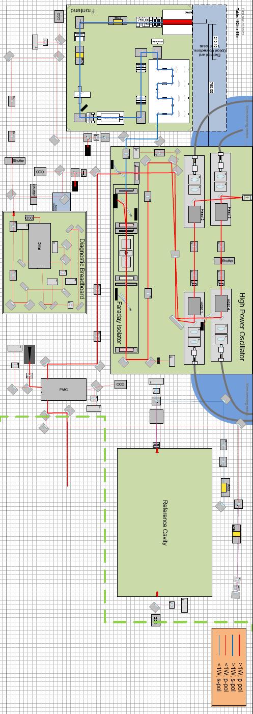
6 the Pre Mode Cleaner (PMC). The diagram of the cavity is shown in Figure 6. Figure 6 Diagram of the PMC. The spatial profile is determined by the length of the cavity. An actuator is placed on one mirror and adjusts the length of the cavity so that the fundamental Gaussian profile is transmitted. The feedback loop is the same as the Pound Drever Hall technique mentioned above with the exception that signal is fed back to the actuator instead of the laser. The PMC is then locked on one laser profile, specifically the fundamental Gaussian mode. The pointing is stabilized by the PMC by carefully designing the cavity such that there is only one closed path for the light. This forces the light to exit in the same direction no matter how the light enters the cavity. The radio frequency intensity fluctuations are filtered out by the PMC because the light takes a finite time to build up in the cavity. As a result, the cavity cannot respond to changes in the radio frequency range and these fluctuations are minimized. Installation The schematic for the Advanced LIGO Pre Stabilized Laser system is shown below in Figure 7. Figure 7 Diagram of AdvLIGO PSL.
7 The orange tilted box on the far left is the seed laser, which outputs a 2 Watt 1064 beam. The beam is immediately picked off at the noise eater for initial intensity stabilization. The beam then passes through and EOM and AOM to add sidebands and a Faraday isolator to stop any reflected beam. The beam is then sent through an amplifier stage that outputs 35 Watts and again is sent through a Faraday isolator. The beam is sent through another amplifier increasing the intensity to 200 Watts. After the high power amplifier, the beam passes through the PMC for spatial, pointing, and RF intensity stabilization. The beam is picked off after the PMC for the intensity stabilization and then is picked off again for the frequency stabilization. The beam then exits the PSL and enters a suspended modecleaner outside the PSL which provides stabilization. The actual layout of the PSL optics table is shown on the next page. The frontend contains the 2 Watt seed laser and the first amplifier and outputs the 35 Watt beam. This beam is injected into the high power oscillator stage where it is amplified to 200 Watts. A small fraction (~300 mw) is also picked off and sent to the Diagnostic Breadboard. A small portion of the 200 Watt output (again ~300 mw) is also picked off and sent to the DBB. The output of the 200 Watt oscillator is sent through the PMC and (again ~300 mw) picked off and sent to the DBB (not shown in diagram). All optical paths not in the green boxes are installed, aligned, and modematched to the appropriate cavity. Modematching is the process of shaping an input beam to an optical cavity. An optical cavity has a resonance condition such that the beam has a waist at a specific location and specific size. Thus, in order to obtain the maximum efficiency of an optical cavity, the input beam must not only be aligned properly, but the beam must also have a waste in the proper location and that waste must be the proper size. This is accomplished by placing lenses in front of the cavity in order to correctly shape the input beam. The location and focal length of the lenses are calculated using the JAMMT software. A screen shot is shown in Figure 8 following the PSL table layout. The waste and size of the beam to be shaped is input and begins at the left. Lenses with known focal lengths are entered and the position of the lenses are adjusted until the desired beam waste and position is obtained. Once this is done, the physical lenses must be installed and adjusted until the maximum power is transmitted through the cavity.
8

9 Figure 8 Screenshot of JAMMT modematching software. Once all the optical paths are aligned and the cavities modematched, the Diagnostic Breadboard can then be used for characterization of different beams. The DBB measures five beam parameters: intensity noise, RF intensity noise, frequency noise, pointing noise, and spatial mode content. Both the intensity and RF intensity noise is measured simply with a photodiode that measures the intensity as a function of time. The time series is then used to compute the noise measurement. The pointing noise is measured with two quadrant photodiodes that measure the position of the beam as a function of time. The time series of the position of the beam is then converted to four pointing noise measurements as there are four degrees of freedom. The frequency noise is measured by holding the length of the modecleaner in the DBB constant and measuring the transmitted power as a function of time. Again the time series in converted to a frequency noise measurement. The mode quality is measured by varying the length of the cavity and measuring the transmitted power as a function of the length of the cavity. Since the length of the cavity determines which mode is resonant this data is then converted to spatial mode content.
10 Results The Diagnostic Breadboard was used to compare beam parameters between the output of the 200 Watt oscillator and downstream of the PMC after the 200 Watt oscillator. The frequency and intensity loops were not yet installed. The data for the intensity noise is plotted in Figure 9 below. Figure 9 Relative intensity noise data. The blue curve represents the AdvLIGO requirement and the green curve is the shot noise from the photodiode. The black curve represents the beam straight out of the 200 Watt oscillator and the red curve is the beam after it has passed through the PMC. The AdvLIGO requirement is most stringent at 10 Hz because this is where AdvLIGO expects to be the most sensitive. Though the data is far from the requirement level, the data is good as the intensity stabilization loop had not yet been installed. The intensity actually increased after the PMC but it is acceptable because it is less than a factor of 2 greater at all frequencies. Figure 10 shows the data for the intensity noise at radio frequencies. The color scheme is the same for this plot. Since the PMC filters out intensity fluctuations at RF, it is expected that the requirement is met. The beam downstream the PMC clearly has less RF intensity noise and is shot noise limited because it reaches a constant value somewhere between 5 and 10 MHz. Figure 11 shows the frequency noise data.
11 Figure 10 Relative intensity noise at radio frequencies. Figure 11 Frequency noise data.
12 In frequency noise plot, the green curve is the AdvLIGO requirement. The blue curve is an estimate of the frequency noise of the NPRO, which is the 2 Watt seed laser. The data clearly does not reach the AdvLIGO requirement but the frequency stabilization loop was not installed when the data was taken. It is expected, however, that the data should follow the estimate of the NPRO. The data is slightly above this curve and the cause is yet unknown. Figure 12 shows modescan data. Figure 12 Modescan data. In this plot, the black curve represents the fit of the fundamental Gaussian mode, the red curve is the modescan of the 200 Watt beam and the blue curve is the modescan of the beam after the PMC. The data clearly shows the PMC filters out most of the higher order modes. The red curve translates into ~7% higher order modes and the blue curve translates into ~1% higher order modes. Since AdvLIGO calls for less than 5% higher order modes, this requirement is easily met. Finally Figure 13 shows the pointing noise data. Again in these plots, the green curve represents the AdvLIGO requirement. In all four cases, the PMC significantly reduced the pointing noise as it should, but did not meet the requirement in most cases. This may not be a problem as there is a larger suspended modecleaner outside the PSL that would further reduce pointing noise.
13 Figure 13 Pointing noise data. Future Work The next step in testing the AdvLIGO PSL is to install the frequency and intensity stabilization loops. Once these systems are installed, a full characterization of the beam downstream the PMC should be measured. This data should then be used to adjust the setup until AdvLIGO requirements are met or nearly met. When the requirements are met, long term stability testing can begin. LIGO must run for several years without need for a new PSL so long term testing is necessary. If long term testing succeeds, the AdvLIGO PSL can be installed at the LIGO sites and bring LIGO one step closer to detecting gravitational waves.
Final Report for IREU 2013
 Final Report for IREU 2013 Seth Brown Albert Einstein Institute IREU 2013 7-20-13 Brown 2 Background Information Albert Einstein s revolutionary idea that gravity is caused by curves in the fabric of space
A gravitational wave is a differential strain in spacetime. Equivalently, it is a differential tidal force that can be sensed by multiple test masses.
 A gravitational wave is a differential strain in spacetime. Equivalently, it is a differential tidal force that can be sensed by multiple test masses. Plus-polarization Cross-polarization 2 Any system
Advanced Virgo commissioning challenges. Julia Casanueva on behalf of the Virgo collaboration
 Advanced Virgo commissioning challenges Julia Casanueva on behalf of the Virgo collaboration GW detectors network Effect on Earth of the passage of a GW change on the distance between test masses Differential
Multiply Resonant EOM for the LIGO 40-meter Interferometer
 LASER INTERFEROMETER GRAVITATIONAL WAVE OBSERVATORY - LIGO - CALIFORNIA INSTITUTE OF TECHNOLOGY MASSACHUSETTS INSTITUTE OF TECHNOLOGY LIGO-XXXXXXX-XX-X Date: 2009/09/25 Multiply Resonant EOM for the LIGO
Optical Vernier Technique for Measuring the Lengths of LIGO Fabry-Perot Resonators
 LASER INTERFEROMETER GRAVITATIONAL WAVE OBSERVATORY -LIGO- CALIFORNIA INSTITUTE OF TECHNOLOGY MASSACHUSETTS INSTITUTE OF TECHNOLOGY Technical Note LIGO-T97074-0- R 0/5/97 Optical Vernier Technique for
Stabilized lasers for advanced gravitational wave detectors
 Early View publication on www.interscience.wiley.com (issue and page numbers not yet assigned; citable using Digital Object Identifier DOI) Laser & Photon. Rev., 1 15 (2010) / DOI 10.1002/lpor.200900036
Preliminary Optical Fiber Stabilization for AdvLIGO Pre-Lock Acquisition System
 T080352-00 Preliminary Optical Fiber Stabilization for AdvLIGO Pre-Lock Acquisition System Jaclyn R. Sanders Mentors: Dick Gustafson, Paul Schwinberg, Daniel Sigg Abstract Advanced LIGO requires a seismic
A review of Pound-Drever-Hall laser frequency locking
 A review of Pound-Drever-Hall laser frequency locking M Nickerson JILA, University of Colorado and NIST, Boulder, CO 80309-0440, USA Email: nickermj@jila.colorado.edu Abstract. This paper reviews the Pound-Drever-Hall
9) Describe the down select process that led to the laser selection in more detail
 Describe the down select process that led to the laser selection in more detail") 9) Describe the down select process that led to the laser selection in more detail David Shoemaker NSF Annual Review of the LIGO Laboratory 18 November 2003 Process Interested research groups pursued separate
9) Describe the down select process that led to the laser selection in more detail David Shoemaker NSF Annual Review of the LIGO Laboratory 18 November 2003 Process Interested research groups pursued separate
Designing Optical Layouts for AEI s 10 meter Prototype. Stephanie Wiele August 5, 2008
 Designing Optical Layouts for AEI s 10 meter Prototype Stephanie Wiele August 5, 2008 This summer I worked at the Albert Einstein Institute for Gravitational Physics as a member of the 10 meter prototype
LIGO-P R. High-Power Fundamental Mode Single-Frequency Laser
 LIGO-P040053-00-R High-Power Fundamental Mode Single-Frequency Laser Maik Frede, Ralf Wilhelm, Dietmar Kracht, Carsten Fallnich Laser Zentrum Hannover, Hollerithallee 8, 30419 Hannover, Germany Phone:+49
The VIRGO injection system
 INSTITUTE OF PHYSICSPUBLISHING Class. Quantum Grav. 19 (2002) 1829 1833 CLASSICAL ANDQUANTUM GRAVITY PII: S0264-9381(02)29349-1 The VIRGO injection system F Bondu, A Brillet, F Cleva, H Heitmann, M Loupias,
The Pre Stabilized Laser for the LIGO Caltech 40m Interferometer: Stability Controls and Characterization.
 LASER INTERFEROMETER GRAVITATIONAL WAVE OBSERVATORY LIGO CALIFORNIA INSTITUTE OF TECHNOLOGY MASSACHUSETTS INSTITUTE OF TECHNOLOGY Document Type LIGO-T010159-00-R 10/15/01 The Pre Stabilized Laser for the
Stabilizing an Interferometric Delay with PI Control
 Stabilizing an Interferometric Delay with PI Control Madeleine Bulkow August 31, 2013 Abstract A Mach-Zhender style interferometric delay can be used to separate a pulses by a precise amount of time, act
The VIRGO detection system
 LIGO-G050017-00-R Paolo La Penna European Gravitational Observatory INPUT R =35 R=0.9 curv =35 0m 95 MOD CLEAN ER (14m )) WI N d:yag plar=0 ne.8 =1λ 064nm 3km 20W 6m 66.4m M odulat or PR BS N I sing lefrequ
Interferometer signal detection system for the VIRGO experiment. VIRGO collaboration
 Interferometer signal detection system for the VIRGO experiment VIRGO collaboration presented by Raffaele Flaminio L.A.P.P., Chemin de Bellevue, Annecy-le-Vieux F-74941, France Abstract VIRGO is a laser
The Virgo detector. L. Rolland LAPP-Annecy GraSPA summer school L. Rolland GraSPA2013 Annecy le Vieux
 The Virgo detector The Virgo detector L. Rolland LAPP-Annecy GraSPA summer school 2013 1 Table of contents Principles Effect of GW on free fall masses Basic detection principle overview Are the Virgo mirrors
R. J. Jones College of Optical Sciences OPTI 511L Fall 2017
 R. J. Jones College of Optical Sciences OPTI 511L Fall 2017 Active Modelocking of a Helium-Neon Laser The generation of short optical pulses is important for a wide variety of applications, from time-resolved
Alignment control of GEO 600
 INSTITUTE OF PHYSICS PUBLISHING Class. Quantum Grav. 1 (4) S441 S449 CLASSICAL AND QUANTUM GRAVITY PII: S64-9381(4)683-1 Alignment of GEO 6 HGrote 1, G Heinzel 1,AFreise 1,SGoßler 1, B Willke 1,HLück 1,
Wave Front Detection for Virgo
 Wave Front Detection for Virgo L.L.Richardson University of Arizona, Steward Observatory, 933 N. Cherry ave, Tucson Arizona 8575, USA E-mail: zimlance@email.arizona.edu Abstract. The use of phase cameras
Optical generation of frequency stable mm-wave radiation using diode laser pumped Nd:YAG lasers
 Optical generation of frequency stable mm-wave radiation using diode laser pumped Nd:YAG lasers T. Day and R. A. Marsland New Focus Inc. 340 Pioneer Way Mountain View CA 94041 (415) 961-2108 R. L. Byer
R. J. Jones Optical Sciences OPTI 511L Fall 2017
 R. J. Jones Optical Sciences OPTI 511L Fall 2017 Semiconductor Lasers (2 weeks) Semiconductor (diode) lasers are by far the most widely used lasers today. Their small size and properties of the light output
Lasers for Advanced Interferometers
 Lasers or Advanced Intererometers Benno Willke Aspen Meeting Aspen CO, February 2004 G040041-00-Z Requirements - Topology Sagnac: broadband source to reduce scattered light noise power control recycled
레이저의주파수안정화방법및그응용 박상언 ( 한국표준과학연구원, 길이시간센터 )
") 레이저의주파수안정화방법및그응용 박상언 ( 한국표준과학연구원, 길이시간센터 ) Contents Frequency references Frequency locking methods Basic principle of loop filter Example of lock box circuits Quantifying frequency stability Applications
레이저의주파수안정화방법및그응용 박상언 ( 한국표준과학연구원, 길이시간센터 ) Contents Frequency references Frequency locking methods Basic principle of loop filter Example of lock box circuits Quantifying frequency stability Applications
CHAPTER 5 FINE-TUNING OF AN ECDL WITH AN INTRACAVITY LIQUID CRYSTAL ELEMENT
 CHAPTER 5 FINE-TUNING OF AN ECDL WITH AN INTRACAVITY LIQUID CRYSTAL ELEMENT In this chapter, the experimental results for fine-tuning of the laser wavelength with an intracavity liquid crystal element
LISA and SMART2 Optical Work in Europe
 LISA and SMART2 Optical Work in Europe David Robertson University of Glasgow Outline Overview of current optical system work Title Funded by Main focus Prime Phase Measuring System LISA SMART2 SEA (Bristol)
Notes on the Pound-Drever-Hall technique
 LASER INTERFEROMETER GRAVITATIONAL WAVE OBSERVATORY -LIGO- CALIFORNIA INSTITUTE OF TECHNOLOGY MASSACHUSETTS INSTITUTE OF TECHNOLOGY Technical Note LIGO-T980045-00- D 4/16/98 Notes on the Pound-Drever-Hall
Results from the Stanford 10 m Sagnac interferometer
 INSTITUTE OF PHYSICSPUBLISHING Class. Quantum Grav. 19 (2002) 1585 1589 CLASSICAL ANDQUANTUM GRAVITY PII: S0264-9381(02)30157-6 Results from the Stanford 10 m Sagnac interferometer Peter T Beyersdorf,
Techniques for the stabilization of the ALPS-II optical cavities
 Techniques for the stabilization of the ALPS-II optical cavities Robin Bähre for the ALPS collaboration 9th PATRAS workshop for Axions, WIMPs and WISPs Schloss Waldthausen, Mainz 2013 Jun 26th Outline
Stability of a Fiber-Fed Heterodyne Interferometer
 Stability of a Fiber-Fed Heterodyne Interferometer Christoph Weichert, Jens Flügge, Paul Köchert, Rainer Köning, Physikalisch Technische Bundesanstalt, Braunschweig, Germany; Rainer Tutsch, Technische
The Florida control scheme. Guido Mueller, Tom Delker, David Reitze, D. B. Tanner
 The Florida control scheme Guido Mueller, Tom Delker, David Reitze, D. B. Tanner Department of Physics, University of Florida, Gainesville 32611-8440, Florida, USA The most likely conguration for the second
Week IX: INTERFEROMETER EXPERIMENTS
 Week IX: INTERFEROMETER EXPERIMENTS Notes on Adjusting the Michelson Interference Caution: Do not touch the mirrors or beam splitters they are front surface and difficult to clean without damaging them.
Experimental Test of an Alignment Sensing Scheme for a Gravitational-wave Interferometer
 Experimental Test of an Alignment Sensing Scheme for a Gravitational-wave Interferometer Nergis Mavalvala *, Daniel Sigg and David Shoemaker LIGO Project Department of Physics and Center for Space Research,
How to Build a Gravitational Wave Detector. Sean Leavey
 How to Build a Gravitational Wave Detector Sean Leavey Supervisors: Dr Stefan Hild and Prof Ken Strain Institute for Gravitational Research, University of Glasgow 6th May 2015 Gravitational Wave Interferometry
TNI mode cleaner/ laser frequency stabilization system
 LASER INTERFEROMETER GRAVITATIONAL WAVE OBSERVATORY -LIGO- CALIFORNIA INSTITUTE OF TECHNOLOGY MASSACHUSETTS INSTITUTE OF TECHNOLOGY Technical Note LIGO-T000077-00- R 8/10/00 TNI mode cleaner/ laser frequency
Laser stabilization and frequency modulation for trapped-ion experiments
 Laser stabilization and frequency modulation for trapped-ion experiments Michael Matter Supervisor: Florian Leupold Semester project at Trapped Ion Quantum Information group July 16, 2014 Abstract A laser
Wavelength Control and Locking with Sub-MHz Precision
 Wavelength Control and Locking with Sub-MHz Precision A PZT actuator on one of the resonator mirrors enables the Verdi output wavelength to be rapidly tuned over a range of several GHz or tightly locked
Optical design of shining light through wall experiments
 Optical design of shining light through wall experiments Benno Willke Leibniz Universität Hannover (member of the ALPS collaboration) Vistas in Axion Physics: A Roadmap for Theoretical and Experimental
visibility values: 1) V1=0.5 2) V2=0.9 3) V3=0.99 b) In the three cases considered, what are the values of FSR (Free Spectral Range) and
 V1=0.5 2) V2=0.9 3) V3=0.99 b) In the three cases considered, what are the values of FSR (Free Spectral Range) and") EXERCISES OF OPTICAL MEASUREMENTS BY ENRICO RANDONE AND CESARE SVELTO EXERCISE 1 A CW laser radiation (λ=2.1 µm) is delivered to a Fabry-Pérot interferometer made of 2 identical plane and parallel mirrors
EXERCISES OF OPTICAL MEASUREMENTS BY ENRICO RANDONE AND CESARE SVELTO EXERCISE 1 A CW laser radiation (λ=2.1 µm) is delivered to a Fabry-Pérot interferometer made of 2 identical plane and parallel mirrors
CO2 laser heating system for thermal compensation of test masses in high power optical cavities. Submitted by: SHUBHAM KUMAR to Prof.
 CO2 laser heating system for thermal compensation of test masses in high power optical cavities. Submitted by: SHUBHAM KUMAR to Prof. DAVID BLAIR Abstract This report gives a description of the setting
The AEI 10 m Prototype. June Sina Köhlenbeck for the 10m Prototype Team
 The AEI 10 m Prototype June 2014 - Sina Köhlenbeck for the 10m Prototype Team The 10m Prototype Seismic attenuation system Suspension Platform Inteferometer SQL Interferometer Suspensions 2 The AEI 10
1.6 Beam Wander vs. Image Jitter
 8 Chapter 1 1.6 Beam Wander vs. Image Jitter It is common at this point to look at beam wander and image jitter and ask what differentiates them. Consider a cooperative optical communication system that
IST IP NOBEL "Next generation Optical network for Broadband European Leadership"
 DBR Tunable Lasers A variation of the DFB laser is the distributed Bragg reflector (DBR) laser. It operates in a similar manner except that the grating, instead of being etched into the gain medium, is
Absolute distance interferometer in LaserTracer geometry
 Absolute distance interferometer in LaserTracer geometry Corresponding author: Karl Meiners-Hagen Abstract 1. Introduction 1 In this paper, a combination of variable synthetic and two-wavelength interferometry
Virgo status and commissioning results
 Virgo status and commissioning results L. Di Fiore for the Virgo Collaboration 5th LISA Symposium 13 july 2004 VIRGO is an French-Italian collaboration for Gravitational Wave research with a 3 km long
arxiv: v1 [gr-qc] 10 Sep 2007
![arxiv: v1 [gr-qc] 10 Sep 2007](/thumbs/74/70185142.jpg "arxiv: v1 [gr-qc] 10 Sep 2007") LIGO P070067 A Z A novel concept for increasing the peak sensitivity of LIGO by detuning the arm cavities arxiv:0709.1488v1 [gr-qc] 10 Sep 2007 1. Introduction S. Hild 1 and A. Freise 2 1 Max-Planck-Institut
LIGO P070067 A Z A novel concept for increasing the peak sensitivity of LIGO by detuning the arm cavities arxiv:0709.1488v1 [gr-qc] 10 Sep 2007 1. Introduction S. Hild 1 and A. Freise 2 1 Max-Planck-Institut
LIGO SURF Report: Three Input Matching/Driving System for Electro-Optic Modulators
 LIGO SURF Report: Three Input Matching/Driving System for Electro-Optic Modulators Lucas Koerner, Northwestern University Mentors: Dr. Dick Gustafson and Dr. Paul Schwinberg, LIGO Hanford Abstract LIGO
The Lightwave Model 142 CW Visible Ring Laser, Beam Splitter, Model ATM- 80A1 Acousto-Optic Modulator, and Fiber Optic Cable Coupler Optics Project
 The Lightwave Model 142 CW Visible Ring Laser, Beam Splitter, Model ATM- 80A1 Acousto-Optic Modulator, and Fiber Optic Cable Coupler Optics Project Stephen W. Jordan Seth Merritt Optics Project PH 464
Pound-Drever-Hall Locking of a Chip External Cavity Laser to a High-Finesse Cavity Using Vescent Photonics Lasers & Locking Electronics
 of a Chip External Cavity Laser to a High-Finesse Cavity Using Vescent Photonics Lasers & Locking Electronics 1. Introduction A Pound-Drever-Hall (PDH) lock 1 of a laser was performed as a precursor to
Commissioning of Advanced Virgo
 Commissioning of Advanced Virgo VSR1 VSR4 VSR5/6/7? Bas Swinkels, European Gravitational Observatory on behalf of the Virgo Collaboration GWADW Takayama, 26/05/2014 B. Swinkels Adv. Virgo Commissioning
Diode Laser Control Electronics. Diode Laser Locking and Linewidth Narrowing. Rudolf Neuhaus, Ph.D. TOPTICA Photonics AG
 Appl-1012 Diode Laser Control Electronics Diode Laser Locking and Linewidth Narrowing Rudolf Neuhaus, Ph.D. TOPTICA Photonics AG Introduction Stabilized diode lasers are well established tools for many
Wave optics and interferometry
 11b, 2013, lab 7 Wave optics and interferometry Note: The optical surfaces used in this experiment are delicate. Please do not touch any of the optic surfaces to avoid scratches and fingerprints. Please
A Thermal Compensation System for the gravitational wave detector Virgo
 A Thermal Compensation System for the gravitational wave detector Virgo M. Di Paolo Emilio University of L Aquila and INFN Roma Tor Vergata On behalf of the Virgo Collaboration Index: 1) Thermal Lensing
LIGO II Photon Drive Conceptual Design
 LIGO II Photon Drive Conceptual Design LIGO-T000113-00-R M. Zucker 10/13/00 ABSTRACT LIGO II will require very small forces to actuate the final stage test masses, due to the high isolation factor and
Lasers for LISA: overview and phase characteristics
 Lasers for LISA: overview and phase characteristics M Tröbs 1, S Barke 1, J Möbius 2,3, M Engelbrecht 2,4, D Kracht 2, L d Arcio 5, G Heinzel 1 and K Danzmann 1 1 AEI Hannover, (MPI für Gravitationsphysik
HIGH POWER LASERS FOR 3 RD GENERATION GRAVITATIONAL WAVE DETECTORS
 HIGH POWER LASERS FOR 3 RD GENERATION GRAVITATIONAL WAVE DETECTORS P. Weßels for the LZH high power laser development team Laser Zentrum Hannover, Germany 23.05.2011 OUTLINE Requirements on lasers for
Modeling and Commisioning of the 10m Prototype Autoalignment System
 Modeling and Commisioning of the 10m Prototype Autoalignment System Luis F. Ortega Albert Einstein Institute Max Planck Insitute Leibniz Universität and University of Florida Department of Physics (Dated:
Koji Arai / Stan Whitcomb LIGO Laboratory / Caltech. LIGO-G v1
 Koji Arai / Stan Whitcomb LIGO Laboratory / Caltech LIGO-G1401144-v1 General Relativity Gravity = Spacetime curvature Gravitational wave = Wave of spacetime curvature Gravitational waves Generated by motion
Compensating thermal lensing in Faraday rotators.
 Compensating thermal lensing in Faraday rotators. Donovan McFeron University of Florida. New Physics Building Corner of Museum and North South Drive Gainesville, FL 36 ( August 3, 000) ABSTRACT An analyzer
First step in the industry-based development of an ultra-stable optical cavity for space applications
 First step in the industry-based development of an ultra-stable optical cavity for space applications B. Argence, E. Prevost, T. Levêque, R. Le Goff, S. Bize, P. Lemonde and G. Santarelli LNE-SYRTE,Observatoire
Testbed for prototypes of the LISA point-ahead angle mechanism
 Testbed for prototypes of the LISA point-ahead angle mechanism, Benjamin Sheard, Gerhard Heinzel and Karsten Danzmann Albert-Einstein-Institut Hannover 7 th LISA Symposium Barcelona, 06/16/2008 Point-ahead
Physics 476LW. Advanced Physics Laboratory - Microwave Optics
 Physics 476LW Advanced Physics Laboratory Microwave Radiation Introduction Setup The purpose of this lab is to better understand the various ways that interference of EM radiation manifests itself. However,
MASSACHUSETTS INSTITUTE OF TECHNOLOGY Department of Electrical Engineering and Computer Science
 Student Name Date MASSACHUSETTS INSTITUTE OF TECHNOLOGY Department of Electrical Engineering and Computer Science 6.161 Modern Optics Project Laboratory Laboratory Exercise No. 6 Fall 2010 Solid-State
Diffractive gratings. in high-precision interferometry. for gravitational wave detection
 Diffractive gratings in high-precision interferometry for gravitational wave detection by Jonathan Mark Hallam A thesis submitted to The University of Birmingham for the degree of DOCTOR OF PHILOSOPHY
Arm Cavity Finesse for Advanced LIGO
 LASER INTERFEROMETER GRAVITATIONAL WAVE OBSERVATORY - LIGO - CALIFORNIA INSTITUTE OF TECHNOLOGY MASSACHUSETTS INSTITUTE OF TECHNOLOGY Technical Note LIGO-T070303-01-D Date: 2007/12/20 Arm Cavity Finesse
DESIGN OF COMPACT PULSED 4 MIRROR LASER WIRE SYSTEM FOR QUICK MEASUREMENT OF ELECTRON BEAM PROFILE
 1 DESIGN OF COMPACT PULSED 4 MIRROR LASER WIRE SYSTEM FOR QUICK MEASUREMENT OF ELECTRON BEAM PROFILE PRESENTED BY- ARPIT RAWANKAR THE GRADUATE UNIVERSITY FOR ADVANCED STUDIES, HAYAMA 2 INDEX 1. Concept
Gravitational Wave Detection and Squeezed Light
 Gravitational Wave Detection and Squeezed Light David Sliski November 16, 2009 1 Introduction Among the revolutionary predictions of Einstein s theory of general relativity is the existence of gravitational
Interference [Hecht Ch. 9]
![Interference [Hecht Ch. 9]](/thumbs/79/79365345.jpg "Interference [Hecht Ch. 9]") Interference [Hecht Ch. 9] Note: Read Ch. 3 & 7 E&M Waves and Superposition of Waves and Meet with TAs and/or Dr. Lai if necessary. General Consideration 1 2 Amplitude Splitting Interferometers If a lightwave
Interference [Hecht Ch. 9] Note: Read Ch. 3 & 7 E&M Waves and Superposition of Waves and Meet with TAs and/or Dr. Lai if necessary. General Consideration 1 2 Amplitude Splitting Interferometers If a lightwave
EE119 Introduction to Optical Engineering Spring 2003 Final Exam. Name:
 EE119 Introduction to Optical Engineering Spring 2003 Final Exam Name: SID: CLOSED BOOK. THREE 8 1/2 X 11 SHEETS OF NOTES, AND SCIENTIFIC POCKET CALCULATOR PERMITTED. TIME ALLOTTED: 180 MINUTES Fundamental
Initial Results from the C-Mod Prototype Polarimeter/Interferometer
 Initial Results from the C-Mod Prototype Polarimeter/Interferometer K. R. Smith, J. Irby, R. Leccacorvi, E. Marmar, R. Murray, R. Vieira October 24-28, 2005 APS-DPP Conference 1 Abstract An FIR interferometer-polarimeter
EE119 Introduction to Optical Engineering Fall 2009 Final Exam. Name:
 EE119 Introduction to Optical Engineering Fall 2009 Final Exam Name: SID: CLOSED BOOK. THREE 8 1/2 X 11 SHEETS OF NOTES, AND SCIENTIFIC POCKET CALCULATOR PERMITTED. TIME ALLOTTED: 180 MINUTES Fundamental
Increasing the laser power incident on the recycling mirrors in the LIGO interferometers
 LASER INTERFEROMETER GRAVITATIONAL WAVE OBSERVATORY -LIGO- CALIFORNIA INSTITUTE OF TECHNOLOGY MASSACHUSETTS INSTITUTE OF TECHNOLOGY Technical Note LIGO-T030288-00-W 12/09/03 Increasing the laser power
Ultra-stable flashlamp-pumped laser *
 SLAC-PUB-10290 September 2002 Ultra-stable flashlamp-pumped laser * A. Brachmann, J. Clendenin, T.Galetto, T. Maruyama, J.Sodja, J. Turner, M. Woods Stanford Linear Accelerator Center, 2575 Sand Hill Rd.,
Cavity with a deformable mirror for tailoring the shape of the eigenmode
 Cavity with a deformable mirror for tailoring the shape of the eigenmode Peter T. Beyersdorf, Stephan Zappe, M. M. Fejer, and Mark Burkhardt We demonstrate an optical cavity that supports an eigenmode
This is a brief report of the measurements I have done in these 2 months.
 40m Report Kentaro Somiya This is a brief report of the measurements I have done in these 2 months. Mach-Zehnder MZ noise spectrum is measured in various conditions. HEPA filter enhances the noise level
Using a Negative Impedance Converter to Dampen Motion in Test Masses
 Using a Negative Impedance Converter to Dampen Motion in Test Masses Isabella Molina, Dr.Harald Lueck, Dr.Sean Leavey, and Dr.Vaishali Adya University of Florida Department of Physics Max Planck Institute
First and second order systems. Part 1: First order systems: RC low pass filter and Thermopile. Goals: Department of Physics
 slide 1 Part 1: First order systems: RC low pass filter and Thermopile Goals: Understand the behavior and how to characterize first order measurement systems Learn how to operate: function generator, oscilloscope,
OPSENS WHITE-LIGHT POLARIZATION INTERFEROMETRY TECHNOLOGY
 OPSENS WHITE-LIGHT POLARIZATION INTERFEROMETRY TECHNOLOGY 1. Introduction Fiber optic sensors are made up of two main parts: the fiber optic transducer (also called the fiber optic gauge or the fiber optic
VIRGO. The status of VIRGO. & INFN - Sezione di Roma 1. 1 / 6/ 2004 Fulvio Ricci
 The status of VIRGO Fulvio Ricci Dipartimento di Fisica - Università di Roma La Sapienza & INFN - Sezione di Roma 1 The geometrical effect of Gravitational Waves The signal the metric tensor perturbation
la. Smith and C.P. Burger Department of Mechanical Engineering Texas A&M University College Station Tx
 INJECTION LOCKED LASERS AS SURF ACE DISPLACEMENT SENSORS la. Smith and C.P. Burger Department of Mechanical Engineering Texas A&M University College Station Tx. 77843 INTRODUCTION In an age where engineered
Design considerations for the RF phase reference distribution system for X-ray FEL and TESLA
 Design considerations for the RF phase reference distribution system for X-ray FEL and TESLA Krzysztof Czuba *a, Henning C. Weddig #b a Institute of Electronic Systems, Warsaw University of Technology,
7th Edoardo Amaldi Conference on Gravitational Waves (Amaldi7)
") Journal of Physics: Conference Series (8) 4 doi:.88/74-6596///4 Lock Acquisition Studies for Advanced Interferometers O Miyakawa, H Yamamoto LIGO Laboratory 8-34, California Institute of Technology, Pasadena,
Journal of Physics: Conference Series (8) 4 doi:.88/74-6596///4 Lock Acquisition Studies for Advanced Interferometers O Miyakawa, H Yamamoto LIGO Laboratory 8-34, California Institute of Technology, Pasadena,
Mechanical Characterization of a LISA Telescope Test Structure
 UNIVERSITY OF TRENTO Faculty of Mathematical, Physical and Natural Sciences Undergraduate school in Physics Mechanical Characterization of a LISA Telescope Test Structure Candidate Ilaria Pucher Advisors
Fiber Pigtailed Variable Frequency Shifters Acousto-optic products
 Fiber Pigtailed Variable Frequency Shifters Acousto-optic products Introduction Frequency Shift LASER DOPPLER VIBROMETER (LDV) 3- PHYSICAL PRINCIPLES MAIN EQUATIONS An RF signal applied to a piezo-electric
HIGH STABILITY LASER FOR INTERFEROMETRIC EARTH GRAVITY MEASUREMENTS
 Launch your visions HIGH STABILITY LASER FOR INTERFEROMETRIC EARTH GRAVITY MEASUREMENTS K. Dahl, K. Nicklaus, M. Herding, X. Wang, N. Beller, O. Fitzau, M. Giesberts, M. Herper, R. A. Williams, G. P. Barwood,
7. Michelson Interferometer
 7. Michelson Interferometer In this lab we are going to observe the interference patterns produced by two spherical waves as well as by two plane waves. We will study the operation of a Michelson interferometer,
The LTP interferometer aboard SMART-2
 The LTP interferometer aboard SMART-2 Gerhard Heinzel Max-Planck-Institut für Gravitationsphysik, (Albert-Einstein-Institut), Hannover, presented at the LISA Symposium, PSU, 22.7.2002 1 What is SMART-2?
Thermal correction of the radii of curvature of mirrors for GEO 600
 INSTITUTE OF PHYSICS PUBLISHING Class. Quantum Grav. 21 (2004) S985 S989 CLASSICAL AND QUANTUM GRAVITY PII: S0264-9381(04)68250-5 Thermal correction of the radii of curvature of mirrors for GEO 600 HLück
Chapter 1 Introduction
 Chapter 1 Introduction 1-1 Preface Telecommunication lasers have evolved substantially since the introduction of the early AlGaAs-based semiconductor lasers in the late 1970s suitable for transmitting
Universal and compact laser stabilization electronics
 top-of-fringe LaseLock LaseLock Universal and compact laser stabilization electronics Compact, stand-alone locking electronics for diode lasers, dye lasers, Ti:Sa lasers, or optical resonators Side-of-fringe
Fabry Perot Resonator (CA-1140)
") Fabry Perot Resonator (CA-1140) The open frame Fabry Perot kit CA-1140 was designed for demonstration and investigation of characteristics like resonance, free spectral range and finesse of a resonator.
Fabry Perot Resonator (CA-1140) The open frame Fabry Perot kit CA-1140 was designed for demonstration and investigation of characteristics like resonance, free spectral range and finesse of a resonator.
OPSENS WHITE-LIGHT POLARIZATION INTERFEROMETRY TECHNOLOGY
 OPSENS WHITE-LIGHT POLARIZATION INTERFEROMETRY TECHNOLOGY 1. Introduction Fiber optic sensors are made up of two main parts: the fiber optic transducer (also called the fiber optic gauge or the fiber optic
DEVELOPING A NARROW LINEWIDTH 657 NM DIODE LASER FOR USE IN A CALCIUM ATOM INTERFEROMETER. Brian Neyenhuis
 DEVELOPING A NARROW LINEWIDTH 657 NM DIODE LASER FOR USE IN A CALCIUM ATOM INTERFEROMETER by Brian Neyenhuis A senior thesis submitted to the faculty of Brigham Young University in partial fulfillment
Calibration of the LIGO displacement actuators via laser frequency modulation
 IOP PUBLISHING Class. Quantum Grav. 27 (21) 2151 (1pp) CLASSICAL AND QUANTUM GRAVITY doi:1.188/264-9381/27/21/2151 Calibration of the LIGO displacement actuators via laser frequency modulation E Goetz
Back-Reflected Light and the Reduction of Nonreciprocal Phase Noise in the Fiber Back-Link on LISA
 Back-Reflected Light and the Reduction of Nonreciprocal Phase Noise in the Fiber Back-Link on LISA Aaron Specter The Laser Interferometer Space Antenna (LISA) is a joint ESA NASA project with the aim of
PHYS 3153 Methods of Experimental Physics II O2. Applications of Interferometry
 Purpose PHYS 3153 Methods of Experimental Physics II O2. Applications of Interferometry In this experiment, you will study the principles and applications of interferometry. Equipment and components PASCO
Deep phase modulation interferometry for test mass measurements on elisa
 for test mass measurements on elisa Thomas Schwarze, Felipe Guzmán Cervantes, Oliver Gerberding, Gerhard Heinzel, Karsten Danzmann AEI Hannover Table of content Introduction elisa Current status & outlook
Intrinsic mirror birefringence measurements for the Any Light Particle Search (ALPS)
") Intrinsic mirror birefringence measurements for the Any Light Particle Search (ALPS) Claire Baum University of Florida August 11, 2016 Abstract In this paper, I use a heterodyne polarimeter to measure
Intrinsic mirror birefringence measurements for the Any Light Particle Search (ALPS) Claire Baum University of Florida August 11, 2016 Abstract In this paper, I use a heterodyne polarimeter to measure
Readout and control of a power-recycled interferometric gravitational wave antenna
 LASER INTERFEROMETER GRAVITATIONAL WAVE OBSERVATORY - LIGO - CALIFORNIA INSTITUTE OF TECHNOLOGY MASSACHUSETTS INSTITUTE OF TECHNOLOGY Publication LIGO-P000008-A - D 10/2/00 Readout and control of a power-recycled
Lab 12 Microwave Optics.
 b Lab 12 Microwave Optics. CAUTION: The output power of the microwave transmitter is well below standard safety levels. Nevertheless, do not look directly into the microwave horn at close range when the