Interference [Hecht Ch. 9]
|
|
|
- Lynette Paul
- 6 years ago
- Views:
Transcription
1 Interference [Hecht Ch. 9] Note: Read Ch. 3 & 7 E&M Waves and Superposition of Waves and Meet with TAs and/or Dr. Lai if necessary. General Consideration 1
2 2


3 Amplitude Splitting Interferometers If a lightwave is split to two and bring back together again at a detector, interference would result, as long as the original coherence between the two had not been destroyed. Examples: Dielectric films, Newtons Rings Wavefront Splitting Interferometers The main problem introducing interference is the sources: they must be coherent. And yet separate, independent, adequately coherent sources, other that the modern laser, don t exist. Thomas Young in his double-beam experiment took a single wavefront, split off from it two coherent portions, and had them interfere. Examples: Young s double slit interferometer, Fresnel s double mirror/prism Mirrored Interferometers Examples: Michelson interferometer, Mach-Zehnder Interferometer, Sagnac Interferometer Multiple Beam Interference Example: Fabry-Perot Interferometer 3

4 Michelson Interferometer 4

5 LIGO: 5
6 Other Mirrored Interferometers 6
7 Amplitude Splitting Interferometer & Anti Reflection (AR) Coating 7
8 8
9 9
10 10
11 11
12 12


13 Wavefront Splitting Interferometers The main problem introducing interference is the sources: they must be coherent. And yet separate, independent, adequately coherent sources, other that the modern laser, don t exist. Thomas Young in his double-beam experiment took a single wavefront, split off from it two coherent portions, and had them interfere. 13

14 Thomas Young performed his famous double slit experiment which seemed to prove that light was a wave. This experiment had profound implications, determining most of nineteenth century physics and resulting in several attempts to discover the ether, or the medium of light propagation. Though the experiment is most notable with light, the fact is that this sort of experiment can be performed with any type of wave, such as water. In the early 1800's (1801 to 1805, depending on the source), Thomas Young conducted his experiment. There was not laser or lamps, how did Young achieve that? 14
15 Basic Coherence Theory [Hecht Ch 12] 15


16 Define Visibility as Temporal coherence (From Wikipedia) Figure 1: The amplitude of a single frequency wave as a function of time t (red) and a copy of the same wave delayed by τ(green). The coherence time of the wave is infinite since it is perfectly correlated with itself for all delays τ. Figure 2: The amplitude of a wave whose phase drifts significantly in time τ c as a function of time t (red) and a copy of the same wave delayed by 2τ c (green). At any particular time t the wave can interfere perfectly with its delayed copy. But, since half the time the red and green waves are in phase and half the time out of phase, when averaged over t any interference disappears at this delay. Temporal coherence is the measure of the average correlation between the value of a wave at any pair of times, separated by delay τ. Temporal coherence tells us how monochromatic a source is. In other words, it characterizes how well a wave can interfere with itself at a different time. The delay over which the phase or amplitude wanders by a significant amount (and hence the correlation decreases by significant amount) is defined as the coherence time τ c. At τ=0 the degree of coherence is perfect whereas it drops significantly by delay τ c. The coherence length L c is defined as the distance the wave travels in time τ c. 16
17 One should be careful not to confuse the coherence time with the time duration of the signal, nor the coherence length with the coherence area (see below). The relationship between coherence time and bandwidth It can be shown that the faster a wave decorrelates (and hence the smaller τ c is) the larger the range of frequencies Δf the wave contains. Thus there is a tradeoff:. In terms of wavelength (fλ = c) this relationship becomes, Formally, this follows from the convolution theorem in mathematics, which relates the Fourier transform of the power spectrum (the intensity of each frequency) to its autocorrelation. Examples of temporal coherence We consider four examples of temporal coherence. A wave containing only a single frequency (monochromatic) is perfectly correlated at all times according to the above relation. (See Figure 1) Conversely, a wave whose phase drifts quickly will have a short coherence time. (See Figure 2) Similarly, pulses (wave packets) of waves, which naturally have a broad range of frequencies, also have a short coherence time since the amplitude of the wave changes quickly. (See Figure 3) Finally, white light, which has a very broad range of frequencies, is a wave which varies quickly in both amplitude and phase. Since it consequently has a very short coherence time (just 10 periods or so), it is often called incoherent. The most monochromatic sources are usually lasers; such high monochromaticity implies long coherence lengths (up to hundreds of meters). For example, a stabilized helium-neon laser can produce light with coherence lengths in excess of 5 m. Not all lasers are monochromatic, however (e.g. for a mode-locked Ti-sapphire laser, Δλ 2 nm - 70 nm). LEDs are characterized by Δλ 50 nm, and tungsten filament lights exhibit Δλ 600 nm, so these sources have shorter coherence times than the most monochromatic lasers. Holography requires light with a long coherence time. In contrast, Optical coherence tomography uses light with a short coherence time. (Why?) 17

 detected at the output of an interferometer plotted as a function of delay τ for the example waves in Figures 2 and 3.")
18 Measurement of temporal coherence Figure 3: The amplitude of a wavepacket whose amplitude changes significantly in time τ c (red) and a copy of the same wave delayed by 2τ c (green) plotted as a function of time t. At any particular time the red and green waves are uncorrelated; one oscillates while the other is constant and so there will be no interference at this delay. Another way of looking at this is the wavepackets are not overlapped in time and so at any particular time there is only one nonzero field so no interference can occur. Figure 4: The time-averaged intensity (blue) detected at the output of an interferometer plotted as a function of delay τ for the example waves in Figures 2 and 3. As the delay is changed by half a period, the interference switches between constructive and destructive. The black lines indicate the interference envelope, which gives the degree of coherence. Although the waves in Figures 2 and 3 have different time durations, they have the same coherence time. In optics, temporal coherence is measured in an interferometer such as the Michelson interferometer or Mach-Zehnder interferometer. In these devices, a wave is combined with a copy of itself that is delayed by time τ. A detector measures the time-averaged intensity of the light exiting the interferometer. The resulting interference visibility (e.g. see Figure 4) gives the temporal coherence at delay τ. Since for most natural light sources, the coherence time is much shorter than the time resolution of any detector, the detector itself does the time averaging. Consider the example shown in Figure 3. At a fixed delay, here 2τ c, an infinitely fast detector would measure an intensity that fluctuates significantly over a time t equal to τ c. In this case, to find the temporal coherence at 2τ c, one would manually time-average the intensity. Spatial coherence In some systems, such as water waves or optics, wave-like states can extend over one or two dimensions. Spatial coherence describes the ability for two points in space, x 1 and x 2, in the extent of a wave to interfere, when averaged over time. More precisely, the spatial coherence is the cross-correlation between two points in a wave for all times. If a wave has only 1 value of amplitude over an infinite length, it is perfectly spatially coherent. The range of separation between the two points over which there is significant interference is called the coherence area, 18

 and finite coherence length. Figure 8: A wave with finite coherence area is incident on a pinhole (small aperture).")

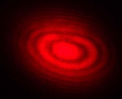
19 A c. This is the relevant type of coherence for the Young s double-slit interferometer. It is also used in optical imaging systems and particularly in various types of astronomy telescopes. Sometimes people also use spatial coherence to refer to the visibility when a wave-like state is combined with a spatially shifted copy of itself. Examples of spatial coherence Spatial coherence Figure 5: A plane wave with an infinite coherence length. Figure 6: A wave with a varying profile (wavefront) and infinite coherence length. Figure 7: A wave with a varying profile (wavefront) and finite coherence length. Figure 8: A wave with finite coherence area is incident on a pinhole (small aperture). The wave will diffract out of the pinhole. Far from the pinhole the emerging spherical wavefronts are approximately flat. The coherence area is now infinite while the coherence length is unchanged. Figure 9: A wave with infinite coherence area is combined with a spatially-shifted copy of itself. Some sections in the wave interfere constructively and some will interfere destructively. Averaging over these sections, a detector with length D will measure reduced interference visibility. For example a misaligned Mach-Zehnder interferometer will do this. Consider a tungsten light-bulb filament. Different points in the filament emit light independently and have no fixed phase-relationship. In detail, at any point in time the profile of the emitted light is going to be distorted. The profile will change randomly over the coherence time τ c. Since for a white-light source such as a light-bulb τ c is small, the filament is considered a spatially incoherent source. In contrast, a radio antenna array, has large spatial coherence because antennas at opposite ends of the array emit with a fixed phase-relationship. Light waves produced by a laser often have high temporal and spatial coherence (though the degree of coherence depends strongly on the exact properties of the laser). Spatial coherence of laser beams also manifests itself as speckle patterns and diffraction fringes seen at the edges of shadow. Holography requires temporally and spatially coherent light. Its inventor, Dennis Gabor, produced successful holograms more than ten years before lasers were invented. To produce coherent light he passed the monochromatic light from an emission line of a mercury-vapor lamp through a pinhole spatial filter. Can you explain why Gabor s method indeed generated a temporally and spatially coherent light? 19
Basics of INTERFEROMETRY
 Basics of INTERFEROMETRY P Hariharan CSIRO Division of Applied Sydney, Australia Physics ACADEMIC PRESS, INC. Harcourt Brace Jovanovich, Publishers Boston San Diego New York London Sydney Tokyo Toronto
Optics and Lasers. Matt Young. Including Fibers and Optical Waveguides
 Matt Young Optics and Lasers Including Fibers and Optical Waveguides Fourth Revised Edition With 188 Figures Springer-Verlag Berlin Heidelberg New York London Paris Tokyo Hong Kong Barcelona Budapest Contents
HUYGENS PRINCIPLE AND INTERFERENCE
 HUYGENS PRINCIPLE AND INTERFERENCE VERY SHORT ANSWER QUESTIONS Q-1. Can we perform Double slit experiment with ultraviolet light? Q-2. If no particular colour of light or wavelength is specified, then
Physical Optics. Diffraction.
 Physical Optics. Diffraction. Interference Young s interference experiment Thin films Coherence and incoherence Michelson interferometer Wave-like characteristics of light Huygens-Fresnel principle Interference.
Imaging Systems Laboratory II. Laboratory 8: The Michelson Interferometer / Diffraction April 30 & May 02, 2002
 1051-232 Imaging Systems Laboratory II Laboratory 8: The Michelson Interferometer / Diffraction April 30 & May 02, 2002 Abstract. In the last lab, you saw that coherent light from two different locations
PhysicsAndMathsTutor.com 1
 PhysicsAndMathsTutor.com 1 Q1. Just over two hundred years ago Thomas Young demonstrated the interference of light by illuminating two closely spaced narrow slits with light from a single light source.
Single Photon Interference Laboratory
 Single Photon Interference Laboratory Renald Dore Institute of Optics University of Rochester, Rochester, NY 14627, U.S.A Abstract The purpose of our laboratories was to observe the wave-particle duality
Basics of INTERFEROMETRY
 Basics of INTERFEROMETRY Second Edition P. HARIHARAN School ofphysics, Sydney, Australia University of Sydney CPi AMSTERDAM BOSTON HEIDELBERG LONDON NEW YORK OXFORD PARIS SAN DIEGO SAN FRANCISCO SINGAPORE
Lab Report 3: Speckle Interferometry LIN PEI-YING, BAIG JOVERIA
 Lab Report 3: Speckle Interferometry LIN PEI-YING, BAIG JOVERIA Abstract: Speckle interferometry (SI) has become a complete technique over the past couple of years and is widely used in many branches of
Unit-23 Michelson Interferometer I
 Unit-23 Michelson Interferometer I Objective: Study the theory and the design of Michelson Interferometer. And use it to measure the wavelength of a light source. Apparatus: Michelson interferometer (include
Department of Mechanical and Aerospace Engineering, Princeton University Department of Astrophysical Sciences, Princeton University ABSTRACT
 Phase and Amplitude Control Ability using Spatial Light Modulators and Zero Path Length Difference Michelson Interferometer Michael G. Littman, Michael Carr, Jim Leighton, Ezekiel Burke, David Spergel
Chapter 36: diffraction
 Chapter 36: diffraction Fresnel and Fraunhofer diffraction Diffraction from a single slit Intensity in the single slit pattern Multiple slits The Diffraction grating X-ray diffraction Circular apertures
Heterodyne Interferometry with a Supercontinuum Local Oscillator. Pavel Gabor Vatican Observatory, 933 N Cherry Ave., Tucson AZ 85721, USA
 **Volume Title** ASP Conference Series, Vol. **Volume Number** **Author** c **Copyright Year** Astronomical Society of the Pacific Heterodyne Interferometry with a Supercontinuum Local Oscillator Pavel
PHYS General Physics II Lab Diffraction Grating
 1 PHYS 1040 - General Physics II Lab Diffraction Grating In this lab you will perform an experiment to understand the interference of light waves when they pass through a diffraction grating and to determine
Physics 431 Final Exam Examples (3:00-5:00 pm 12/16/2009) TIME ALLOTTED: 120 MINUTES Name: Signature:
 TIME ALLOTTED: 120 MINUTES Name: Signature:") Physics 431 Final Exam Examples (3:00-5:00 pm 12/16/2009) TIME ALLOTTED: 120 MINUTES Name: PID: Signature: CLOSED BOOK. TWO 8 1/2 X 11 SHEET OF NOTES (double sided is allowed), AND SCIENTIFIC POCKET CALCULATOR
Physics 431 Final Exam Examples (3:00-5:00 pm 12/16/2009) TIME ALLOTTED: 120 MINUTES Name: PID: Signature: CLOSED BOOK. TWO 8 1/2 X 11 SHEET OF NOTES (double sided is allowed), AND SCIENTIFIC POCKET CALCULATOR
Tuesday, Nov. 9 Chapter 12: Wave Optics
 Tuesday, Nov. 9 Chapter 12: Wave Optics We are here Geometric optics compared to wave optics Phase Interference Coherence Huygens principle & diffraction Slits and gratings Diffraction patterns & spectra
The diffraction of light
 7 The diffraction of light 7.1 Introduction As introduced in Chapter 6, the reciprocal lattice is the basis upon which the geometry of X-ray and electron diffraction patterns can be most easily understood
Design of a digital holographic interferometer for the. ZaP Flow Z-Pinch
 Design of a digital holographic interferometer for the M. P. Ross, U. Shumlak, R. P. Golingo, B. A. Nelson, S. D. Knecht, M. C. Hughes, R. J. Oberto University of Washington, Seattle, USA Abstract The
Gerhard K. Ackermann and Jurgen Eichler. Holography. A Practical Approach BICENTENNIAL. WILEY-VCH Verlag GmbH & Co. KGaA
 Gerhard K. Ackermann and Jurgen Eichler Holography A Practical Approach BICENTENNIAL BICENTENNIAL WILEY-VCH Verlag GmbH & Co. KGaA Contents Preface XVII Part 1 Fundamentals of Holography 1 1 Introduction
Physics. Light Waves & Physical Optics
 Physics Light Waves & Physical Optics Physical Optics Physical optics or wave optics, involves the effects of light waves that are not related to the geometric ray optics covered previously. We will use
Sensitive measurement of partial coherence using a pinhole array
 1.3 Sensitive measurement of partial coherence using a pinhole array Paul Petruck 1, Rainer Riesenberg 1, Richard Kowarschik 2 1 Institute of Photonic Technology, Albert-Einstein-Strasse 9, 07747 Jena,
Lithography. 3 rd. lecture: introduction. Prof. Yosi Shacham-Diamand. Fall 2004
 Lithography 3 rd lecture: introduction Prof. Yosi Shacham-Diamand Fall 2004 1 List of content Fundamental principles Characteristics parameters Exposure systems 2 Fundamental principles Aerial Image Exposure
PHY 431 Homework Set #5 Due Nov. 20 at the start of class
 PHY 431 Homework Set #5 Due Nov. 0 at the start of class 1) Newton s rings (10%) The radius of curvature of the convex surface of a plano-convex lens is 30 cm. The lens is placed with its convex side down
Important performance parameters when considering lasers for holographic applications
 Important performance parameters when considering lasers for holographic applications E.K. Illy*, H. Karlsson & G. Elgcrona. Cobolt AB, a part of HÜBNER Photonics, Vretenvägen 13, 17154, Stockholm, Sweden.
Week IX: INTERFEROMETER EXPERIMENTS
 Week IX: INTERFEROMETER EXPERIMENTS Notes on Adjusting the Michelson Interference Caution: Do not touch the mirrors or beam splitters they are front surface and difficult to clean without damaging them.
Observational Astronomy
 Observational Astronomy Instruments The telescope- instruments combination forms a tightly coupled system: Telescope = collecting photons and forming an image Instruments = registering and analyzing the
PhysFest. Holography. Overview
 PhysFest Holography Holography (from the Greek, holos whole + graphe writing) is the science of producing holograms, an advanced form of photography that allows an image to be recorded in three dimensions.
Exam 3--PHYS 102--S10
 ame: Exam 3--PHYS 02--S0 Multiple Choice Identify the choice that best completes the statement or answers the question.. At an intersection of hospital hallways, a convex mirror is mounted high on a wall
Physics 476LW. Advanced Physics Laboratory - Microwave Optics
 Physics 476LW Advanced Physics Laboratory Microwave Radiation Introduction Setup The purpose of this lab is to better understand the various ways that interference of EM radiation manifests itself. However,
Holography (A13) Christopher Bronner, Frank Essenberger Freie Universität Berlin Tutor: Dr. Fidder. July 1, 2007 Experiment on July 2, 2007
 Christopher Bronner, Frank Essenberger Freie Universität Berlin Tutor: Dr. Fidder. July 1, 2007 Experiment on July 2, 2007") Holography (A13) Christopher Bronner, Frank Essenberger Freie Universität Berlin Tutor: Dr. Fidder July 1, 2007 Experiment on July 2, 2007 1 Preparation 1.1 Normal camera If we take a picture with a camera,
Holography (A13) Christopher Bronner, Frank Essenberger Freie Universität Berlin Tutor: Dr. Fidder July 1, 2007 Experiment on July 2, 2007 1 Preparation 1.1 Normal camera If we take a picture with a camera,
LOS 1 LASER OPTICS SET
 LOS 1 LASER OPTICS SET Contents 1 Introduction 3 2 Light interference 5 2.1 Light interference on a thin glass plate 6 2.2 Michelson s interferometer 7 3 Light diffraction 13 3.1 Light diffraction on a
R.B.V.R.R. WOMEN S COLLEGE (AUTONOMOUS) Narayanaguda, Hyderabad.
 Narayanaguda, Hyderabad.") R.B.V.R.R. WOMEN S COLLEGE (AUTONOMOUS) Narayanaguda, Hyderabad. DEPARTMENT OF PHYSICS QUESTION BANK FOR SEMESTER III PAPER III OPTICS UNIT I: 1. MATRIX METHODS IN PARAXIAL OPTICS 2. ABERATIONS UNIT II
R.B.V.R.R. WOMEN S COLLEGE (AUTONOMOUS) Narayanaguda, Hyderabad. DEPARTMENT OF PHYSICS QUESTION BANK FOR SEMESTER III PAPER III OPTICS UNIT I: 1. MATRIX METHODS IN PARAXIAL OPTICS 2. ABERATIONS UNIT II
LECTURE 26: Interference
 ANNOUNCEMENT *Final: Thursday December 14, 2017, 1 PM 3 PM *Location: Elliot Hall of Music *Covers all readings, lectures, homework from Chapters 28.6 through 33. *The exam will be multiple choice. Be
N.N.Soboleva, S.M.Kozel, G.R.Lockshin, MA. Entin, K.V. Galichsky, P.L. Lebedinsky, P.M. Zhdanovich. Moscow Institute ofphysics and Technology
 Computer assisted optics teaching at the Moscow Institute ofphysics and Technology N.N.Soboleva, S.M.Kozel, G.R.Lockshin, MA. Entin, K.V. Galichsky, P.L. Lebedinsky, P.M. Zhdanovich Moscow Institute ofphysics
Exercise 8: Interference and diffraction
 Physics 223 Name: Exercise 8: Interference and diffraction 1. In a two-slit Young s interference experiment, the aperture (the mask with the two slits) to screen distance is 2.0 m, and a red light of wavelength
MASSACHUSETTS INSTITUTE OF TECHNOLOGY Department of Electrical Engineering and Computer Science
 Student Name Date MASSACHUSETTS INSTITUTE OF TECHNOLOGY Department of Electrical Engineering and Computer Science 6.161 Modern Optics Project Laboratory Laboratory Exercise No. 6 Fall 2010 Solid-State
Optical Signal Processing
 Optical Signal Processing ANTHONY VANDERLUGT North Carolina State University Raleigh, North Carolina A Wiley-Interscience Publication John Wiley & Sons, Inc. New York / Chichester / Brisbane / Toronto
Optical Information Processing. Adolf W. Lohmann. Edited by Stefan Sinzinger. Ch>
 Optical Information Processing Adolf W. Lohmann Edited by Stefan Sinzinger Ch> Universitätsverlag Ilmenau 2006 Contents Preface to the 2006 edition 13 Preface to the third edition 15 Preface volume 1 17
Introduction to Interferometry. Michelson Interferometer. Fourier Transforms. Optics: holes in a mask. Two ways of understanding interferometry
 Introduction to Interferometry P.J.Diamond MERLIN/VLBI National Facility Jodrell Bank Observatory University of Manchester ERIS: 5 Sept 005 Aim to lay the groundwork for following talks Discuss: General
EE119 Introduction to Optical Engineering Spring 2003 Final Exam. Name:
 EE119 Introduction to Optical Engineering Spring 2003 Final Exam Name: SID: CLOSED BOOK. THREE 8 1/2 X 11 SHEETS OF NOTES, AND SCIENTIFIC POCKET CALCULATOR PERMITTED. TIME ALLOTTED: 180 MINUTES Fundamental
Chapter 35. Interference. Optical Interference: Interference of light waves, applied in many branches of science.
 Chapter 35 Interference 35.1: What is the physics behind interference? Optical Interference: Interference of light waves, applied in many branches of science. Fig. 35-1 The blue of the top surface of a
1.6 Beam Wander vs. Image Jitter
 8 Chapter 1 1.6 Beam Wander vs. Image Jitter It is common at this point to look at beam wander and image jitter and ask what differentiates them. Consider a cooperative optical communication system that
Interferometry I Parkes Radio School Jamie Stevens ATCA Senior Systems Scientist
 Interferometry I Parkes Radio School 2011 Jamie Stevens ATCA Senior Systems Scientist 2011-09-28 References This talk will reuse material from many previous Radio School talks, and from the excellent textbook
(51) Int Cl.: G01B 9/02 ( ) G01B 11/24 ( ) G01N 21/47 ( )
 Int Cl.: G01B 9/02 ( ) G01B 11/24 ( ) G01N 21/47 ( )") (19) (12) EUROPEAN PATENT APPLICATION (11) EP 1 939 581 A1 (43) Date of publication: 02.07.2008 Bulletin 2008/27 (21) Application number: 07405346.3 (51) Int Cl.: G01B 9/02 (2006.01) G01B 11/24 (2006.01)
(19) (12) EUROPEAN PATENT APPLICATION (11) EP 1 939 581 A1 (43) Date of publication: 02.07.2008 Bulletin 2008/27 (21) Application number: 07405346.3 (51) Int Cl.: G01B 9/02 (2006.01) G01B 11/24 (2006.01)
Spatial-Phase-Shift Imaging Interferometry Using Spectrally Modulated White Light Source
 Spatial-Phase-Shift Imaging Interferometry Using Spectrally Modulated White Light Source Shlomi Epshtein, 1 Alon Harris, 2 Igor Yaacobovitz, 1 Garrett Locketz, 3 Yitzhak Yitzhaky, 4 Yoel Arieli, 5* 1AdOM
FRAUNHOFER AND FRESNEL DIFFRACTION IN ONE DIMENSION
 FRAUNHOFER AND FRESNEL DIFFRACTION IN ONE DIMENSION Revised November 15, 2017 INTRODUCTION The simplest and most commonly described examples of diffraction and interference from two-dimensional apertures
AP B Webreview ch 24 diffraction and interference
 Name: Class: _ Date: _ AP B Webreview ch 24 diffraction and interference Multiple Choice Identify the choice that best completes the statement or answers the question.. In order to produce a sustained
Figure1. To construct a light pulse, the electric component of the plane wave should be multiplied with a bell shaped function.
 Introduction The Electric field of a monochromatic plane wave is given by is the angular frequency of the plane wave. The plot of this function is given by a cosine function as shown in the following graph.
Dynamic Phase-Shifting Electronic Speckle Pattern Interferometer
 Dynamic Phase-Shifting Electronic Speckle Pattern Interferometer Michael North Morris, James Millerd, Neal Brock, John Hayes and *Babak Saif 4D Technology Corporation, 3280 E. Hemisphere Loop Suite 146,
Option G 4:Diffraction
 Name: Date: Option G 4:Diffraction 1. This question is about optical resolution. The two point sources shown in the diagram below (not to scale) emit light of the same frequency. The light is incident
Swept Wavelength Testing:
 Application Note 13 Swept Wavelength Testing: Characterizing the Tuning Linearity of Tunable Laser Sources In a swept-wavelength measurement system, the wavelength of a tunable laser source (TLS) is swept
MASSACHUSETTS INSTITUTE OF TECHNOLOGY Mechanical Engineering Department. 2.71/2.710 Final Exam. May 21, Duration: 3 hours (9 am-12 noon)
") MASSACHUSETTS INSTITUTE OF TECHNOLOGY Mechanical Engineering Department 2.71/2.710 Final Exam May 21, 2013 Duration: 3 hours (9 am-12 noon) CLOSED BOOK Total pages: 5 Name: PLEASE RETURN THIS BOOKLET WITH
MASSACHUSETTS INSTITUTE OF TECHNOLOGY Mechanical Engineering Department 2.71/2.710 Final Exam May 21, 2013 Duration: 3 hours (9 am-12 noon) CLOSED BOOK Total pages: 5 Name: PLEASE RETURN THIS BOOKLET WITH
Installation and Characterization of the Advanced LIGO 200 Watt PSL
 Installation and Characterization of the Advanced LIGO 200 Watt PSL Nicholas Langellier Mentor: Benno Willke Background and Motivation Albert Einstein's published his General Theory of Relativity in 1916,
Chapter Ray and Wave Optics
 109 Chapter Ray and Wave Optics 1. An astronomical telescope has a large aperture to [2002] reduce spherical aberration have high resolution increase span of observation have low dispersion. 2. If two
Wave optics and interferometry
 11b, 2013, lab 7 Wave optics and interferometry Note: The optical surfaces used in this experiment are delicate. Please do not touch any of the optic surfaces to avoid scratches and fingerprints. Please
An Imaging White Light Velocimeter
 UCRL-JC-125275 PREPRINT An Imaging White Light Velocimeter D. Erskine N.C. Holmes This paper was prepared for submittal to the Optical Society of America Annual Meeting Rochester, NY October 20-25, 1996
Principles of Optics for Engineers
 Principles of Optics for Engineers Uniting historically different approaches by presenting optical analyses as solutions of Maxwell s equations, this unique book enables students and practicing engineers
GRENOUILLE.
 GRENOUILLE Measuring ultrashort laser pulses the shortest events ever created has always been a challenge. For many years, it was possible to create ultrashort pulses, but not to measure them. Techniques
SUPPLEMENTARY INFORMATION
 Optically reconfigurable metasurfaces and photonic devices based on phase change materials S1: Schematic diagram of the experimental setup. A Ti-Sapphire femtosecond laser (Coherent Chameleon Vision S)
Chapter 17: Wave Optics. What is Light? The Models of Light 1/11/13
 Chapter 17: Wave Optics Key Terms Wave model Ray model Diffraction Refraction Fringe spacing Diffraction grating Thin-film interference What is Light? Light is the chameleon of the physical world. Under
General Physics Laboratory Experiment Report 2nd Semester, Year 2018
 PAGE 1/13 Exp. #2-7 : Measurement of the Characteristics of the Light Interference by Using Double Slits and a Computer Interface Measurement of the Light Wavelength and the Index of Refraction of the
Chapter Wave Optics. MockTime.com. Ans: (d)
") Chapter Wave Optics Q1. Which one of the following phenomena is not explained by Huygen s construction of wave front? [1988] (a) Refraction Reflection Diffraction Origin of spectra Q2. Which of the following
Chapter Wave Optics Q1. Which one of the following phenomena is not explained by Huygen s construction of wave front? [1988] (a) Refraction Reflection Diffraction Origin of spectra Q2. Which of the following
LlIGHT REVIEW PART 2 DOWNLOAD, PRINT and submit for 100 points
 WRITE ON SCANTRON WITH NUMBER 2 PENCIL DO NOT WRITE ON THIS TEST LlIGHT REVIEW PART 2 DOWNLOAD, PRINT and submit for 100 points Multiple Choice Identify the choice that best completes the statement or
Order Overlap. A single wavelength constructively interferes in several directions A given direction can receive multiple wavelengths.
 Order Overlap A single wavelength constructively interferes in several directions A given direction can receive multiple wavelengths. Spectral Calibration TripleSpec Users Guide Spectral Calibration TripleSpec
Diffraction Single-slit Double-slit Diffraction grating Limit on resolution X-ray diffraction. Phys 2435: Chap. 36, Pg 1
 Diffraction Single-slit Double-slit Diffraction grating Limit on resolution X-ray diffraction Phys 2435: Chap. 36, Pg 1 Single Slit New Topic Phys 2435: Chap. 36, Pg 2 Diffraction: bending of light around
Diffraction. Interference with more than 2 beams. Diffraction gratings. Diffraction by an aperture. Diffraction of a laser beam
 Diffraction Interference with more than 2 beams 3, 4, 5 beams Large number of beams Diffraction gratings Equation Uses Diffraction by an aperture Huygen s principle again, Fresnel zones, Arago s spot Qualitative
A progressive wave of frequency 150 Hz travels along a stretched string at a speed of 30 m s 1.
 1. progressive wave of frequency 150 Hz travels along a stretched string at a speed of 30 m s 1. What is the phase difference between two points that are 50 mm apart on the string? zero 90 180 360 2 Which
MASSACHUSETTS INSTITUTE OF TECHNOLOGY. 2.71/2.710 Optics Spring 14 Practice Problems Posted May 11, 2014
 MASSACHUSETTS INSTITUTE OF TECHNOLOGY 2.71/2.710 Optics Spring 14 Practice Problems Posted May 11, 2014 1. (Pedrotti 13-21) A glass plate is sprayed with uniform opaque particles. When a distant point
Lecture 04: Solar Imaging Instruments
 Hale COLLAGE (NJIT Phys-780) Topics in Solar Observation Techniques Lecture 04: Solar Imaging Instruments Wenda Cao New Jersey Institute of Technology Valentin M. Pillet National Solar Observatory SDO
Optical Coherence: Recreation of the Experiment of Thompson and Wolf
 Optical Coherence: Recreation of the Experiment of Thompson and Wolf David Collins Senior project Department of Physics, California Polytechnic State University San Luis Obispo June 2010 Abstract The purpose
A novel tunable diode laser using volume holographic gratings
 A novel tunable diode laser using volume holographic gratings Christophe Moser *, Lawrence Ho and Frank Havermeyer Ondax, Inc. 85 E. Duarte Road, Monrovia, CA 9116, USA ABSTRACT We have developed a self-aligned
OPTI 511L Fall (Part 1 of 2)
") Prof. R.J. Jones OPTI 511L Fall 2016 (Part 1 of 2) Optical Sciences Experiment 1: The HeNe Laser, Gaussian beams, and optical cavities (3 weeks total) In these experiments we explore the characteristics
Prof. R.J. Jones OPTI 511L Fall 2016 (Part 1 of 2) Optical Sciences Experiment 1: The HeNe Laser, Gaussian beams, and optical cavities (3 weeks total) In these experiments we explore the characteristics
PHYS 415: OPTICS. Introduction to the Course
 PHYS 415: OPTICS Introduction to the Course F. ÖMER ILDAY Department of Physics, Bilkent University, Ankara, Turkey I used the following resources in the preparation of almost all these lectures: Trebino
AS Physics Unit 5 - Waves 1
 AS Physics Unit 5 - Waves 1 WHAT IS WAVE MOTION? The wave motion is a means of transferring energy from one point to another without the transfer of any matter between the points. Waves may be classified
Lecture 2: Interference
 Lecture 2: Interference λ S 1 d S 2 Lecture 2, p.1 Today Interference of sound waves Two-slit interference Lecture 2, p.2 Review: Wave Summary ( ) ( ) The formula y x,t = Acoskx ωt describes a harmonic
Infrared broadband 50%-50% beam splitters for s- polarized light
 University of New Orleans ScholarWorks@UNO Electrical Engineering Faculty Publications Department of Electrical Engineering 7-1-2006 Infrared broadband 50%-50% beam splitters for s- polarized light R.
Experiment 1: Fraunhofer Diffraction of Light by a Single Slit
 Experiment 1: Fraunhofer Diffraction of Light by a Single Slit Purpose 1. To understand the theory of Fraunhofer diffraction of light at a single slit and at a circular aperture; 2. To learn how to measure
Spectroscopy in the UV and Visible: Instrumentation. Spectroscopy in the UV and Visible: Instrumentation
 Spectroscopy in the UV and Visible: Instrumentation Typical UV-VIS instrument 1 Source - Disperser Sample (Blank) Detector Readout Monitor the relative response of the sample signal to the blank Transmittance
CHAPTER 2 WIRELESS CHANNEL
 CHAPTER 2 WIRELESS CHANNEL 2.1 INTRODUCTION In mobile radio channel there is certain fundamental limitation on the performance of wireless communication system. There are many obstructions between transmitter
Simultaneous Measurements for Tunable Laser Source Linewidth with Homodyne Detection
 Simultaneous Measurements for Tunable Laser Source Linewidth with Homodyne Detection Adnan H. Ali Technical college / Baghdad- Iraq Tel: 96-4-770-794-8995 E-mail: Adnan_h_ali@yahoo.com Received: April
PHYS 3153 Methods of Experimental Physics II O2. Applications of Interferometry
 Purpose PHYS 3153 Methods of Experimental Physics II O2. Applications of Interferometry In this experiment, you will study the principles and applications of interferometry. Equipment and components PASCO
( ) Deriving the Lens Transmittance Function. Thin lens transmission is given by a phase with unit magnitude.
 Deriving the Lens Transmittance Function. Thin lens transmission is given by a phase with unit magnitude.") Deriving the Lens Transmittance Function Thin lens transmission is given by a phase with unit magnitude. t(x, y) = exp[ jk o ]exp[ jk(n 1) (x, y) ] Find the thickness function for left half of the lens
Deriving the Lens Transmittance Function Thin lens transmission is given by a phase with unit magnitude. t(x, y) = exp[ jk o ]exp[ jk(n 1) (x, y) ] Find the thickness function for left half of the lens
The equipment used share any common features regardless of the! being measured. Electronic detection was not always available.
 The equipment used share any common features regardless of the! being measured. Each will have a light source sample cell! selector We ll now look at various equipment types. Electronic detection was not
Physics 3340 Spring Fourier Optics
 Physics 3340 Spring 011 Purpose Fourier Optics In this experiment we will show how the Fraunhofer diffraction pattern or spatial Fourier transform of an object can be observed within an optical system.
GIST OF THE UNIT BASED ON DIFFERENT CONCEPTS IN THE UNIT (BRIEFLY AS POINT WISE). RAY OPTICS
. RAY OPTICS") 209 GIST OF THE UNIT BASED ON DIFFERENT CONCEPTS IN THE UNIT (BRIEFLY AS POINT WISE). RAY OPTICS Reflection of light: - The bouncing of light back into the same medium from a surface is called reflection
209 GIST OF THE UNIT BASED ON DIFFERENT CONCEPTS IN THE UNIT (BRIEFLY AS POINT WISE). RAY OPTICS Reflection of light: - The bouncing of light back into the same medium from a surface is called reflection
Concepts of optical signal processing and optical communications
 Concepts of optical signal processing and optical communications Electronic components allowing to control electric currents with electric currents (or voltages) and integration of a large number of such
Prac%ce Quiz 2. These are Q s from old quizzes. I do not guarantee that the Q s on this year s quiz will be the same, or even similar.
 Prac%ce Quiz 2 These are Q s from old quizzes. I do not guarantee that the Q s on this year s quiz will be the same, or even similar. A laser beam shines vertically upwards. What laser power is needed
that this was due Diffraction: can hear notice it - one way to ripple tanks visualize wide, - if the slit is less than directions
 Lecture Notes (When Light Waves Interfere) Intro: - Newton believed that light was composed of fast-moving, tiny particles which he called corpuscles - Grimaldi, an Italian scientist, discovered in the
EE119 Introduction to Optical Engineering Spring 2002 Final Exam. Name:
 EE119 Introduction to Optical Engineering Spring 2002 Final Exam Name: SID: CLOSED BOOK. FOUR 8 1/2 X 11 SHEETS OF NOTES, AND SCIENTIFIC POCKET CALCULATOR PERMITTED. TIME ALLOTTED: 180 MINUTES Fundamental
Absentee layer. A layer of dielectric material, transparent in the transmission region of
 Glossary of Terms A Absentee layer. A layer of dielectric material, transparent in the transmission region of the filter, due to a phase thickness of 180. Absorption curve, absorption spectrum. The relative
Temporal coherence characteristics of a superluminescent diode system with an optical feedback mechanism
 VI Temporal coherence characteristics of a superluminescent diode system with an optical feedback mechanism Fang-Wen Sheu and Pei-Ling Luo Department of Applied Physics, National Chiayi University, Chiayi
Chapter 23 Study Questions Name: Class:
 Chapter 23 Study Questions Name: Class: Multiple Choice Identify the letter of the choice that best completes the statement or answers the question. 1. When you look at yourself in a plane mirror, you
6 Experiment II: Law of Reflection
 Lab 6: Microwaves 3 Suggested Reading Refer to the relevant chapters, 1 Introduction Refer to Appendix D for photos of the apparatus This lab allows you to test the laws of reflection, refraction and diffraction
Engineering Sciences 151. Electromagnetic Communication Laboratory Assignment 4 Fall Term
 Engineering Sciences 151 Electromagnetic Communication Laboratory Assignment 4 Fall Term 1997-98 OBJECTIVES: To build familiarity with interference phenomena and interferometric measurement techniques;
Stability of a Fiber-Fed Heterodyne Interferometer
 Stability of a Fiber-Fed Heterodyne Interferometer Christoph Weichert, Jens Flügge, Paul Köchert, Rainer Köning, Physikalisch Technische Bundesanstalt, Braunschweig, Germany; Rainer Tutsch, Technische
Diffuser / Homogenizer - diffractive optics
 Diffuser / Homogenizer - diffractive optics Introduction Homogenizer (HM) product line can be useful in many applications requiring a well-defined beam shape with a randomly-diffused intensity profile.
The electric field for the wave sketched in Fig. 3-1 can be written as
 ELECTROMAGNETIC WAVES Light consists of an electric field and a magnetic field that oscillate at very high rates, of the order of 10 14 Hz. These fields travel in wavelike fashion at very high speeds.
HOLOGRAPHY EXPERIMENT 25. Equipment List:-
 EXPERIMENT 25 HOLOGRAPHY Equipment List:- (a) (b) (c) (d) (e) (f) (g) Holography camera and plate holders Laser/beam lamp and assembly Shutter on stand Light meter Objects to make holographs of Holographic
Be aware that there is no universal notation for the various quantities.
 Fourier Optics v2.4 Ray tracing is limited in its ability to describe optics because it ignores the wave properties of light. Diffraction is needed to explain image spatial resolution and contrast and
Collimation Tester Instructions
 Description Use shear-plate collimation testers to examine and adjust the collimation of laser light, or to measure the wavefront curvature and divergence/convergence magnitude of large-radius optical