URBANA. '[."'ffo's STATE GEOLOGICAL SURVEY
|
|
|
- Della Pearson
- 6 years ago
- Views:
Transcription


1


2 URBANA '[."'ffo's STATE GEOLOGICAL SURVEY

3


4 Digitized by the Internet Archive in 2012 with funding from University of Illinois Urbana-Champaign


5 STATE OF ILLINOIS DWIGHT H. GREEN, Governor DEPARTMENT OF REGISTRATION AND EDUCATION FRANK G. THOMPSON, Director DIVISION OF THE STATE GEOLOGICAL SURVEY M. M. LEIGHTON, Chief URBANA CIRCULAR NO. 110 THE STRUCTURE DIORAMA BY FREDERICK SQUIRES REPRINTED FROM THE OIL AND GAS JOURNAL VOL. 43, NO. 15, AUGUST 19, 1944 PRINTED BY AUTHORITY OF THE STATE OF ILLINOIS URBANA, ILLINOIS 1944

6


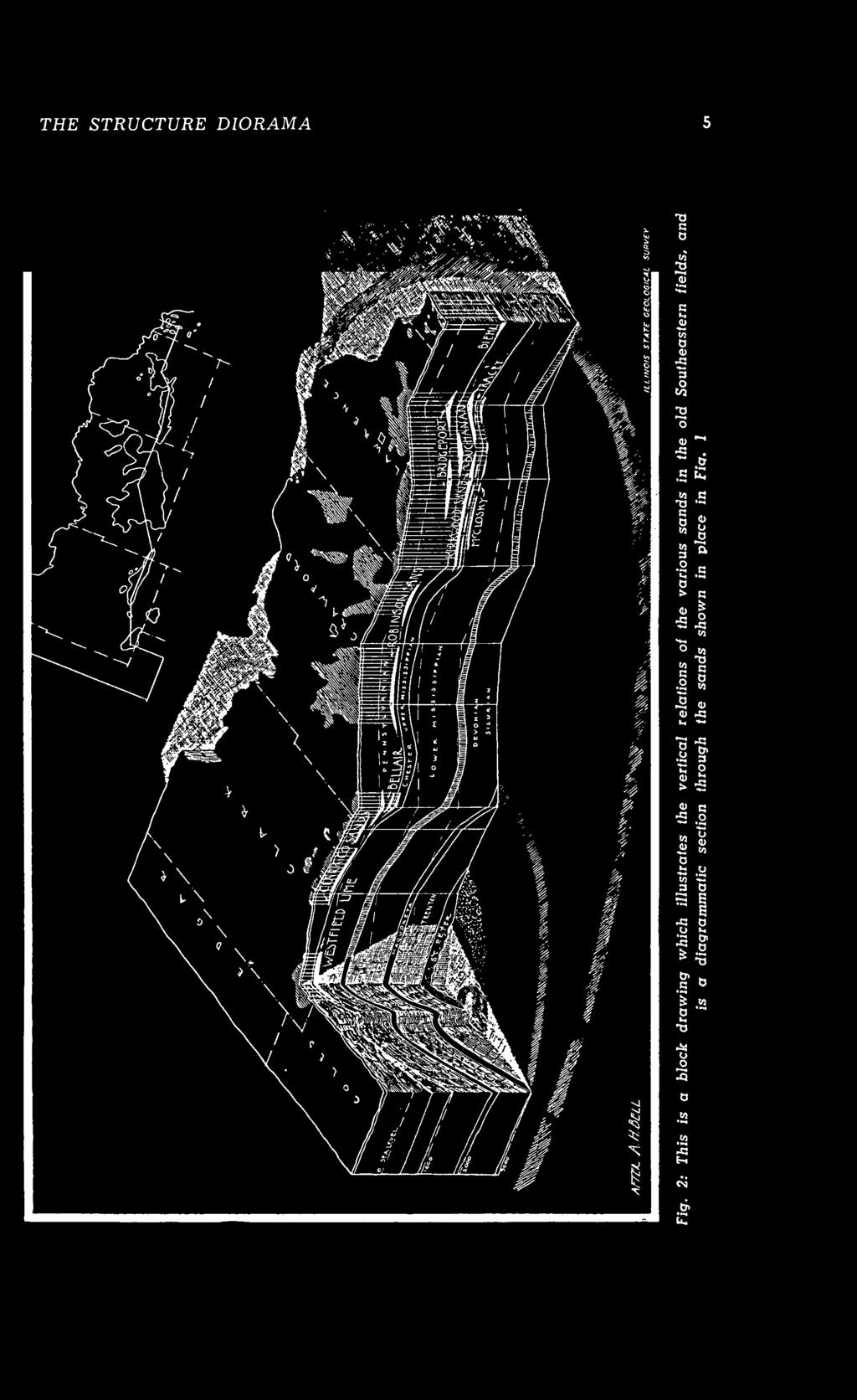
7 The Structure Diorama By Frederick Squires QOME time ago the writer had oc- ^ casion to investigate the Lawrence County, Illinois, oil-producing sands. These occur in five principal strata, but when the wells producing from all of them were shown together on one production map, the sand or sands from which each well was producing being named only on the well itself, considerable confusion arose as to the outline and extent of each single producing stratum. Division Into Separate Sands This confusion was obviated by making a separate map of each sand, and the five maps are here reproduced as Fig. 1. Fig. 2 is a block diagram showing a vertical section through the same sands. Each producing-sand area was then painted in a distinctive color on a separate sheet of glass, and the glass plates were then superimposed in a frame so that the vertical relation of each sand area would be plainly and accurately shown in relation to the others (Fig. 3). These, of course, were shown on separate horizontal planes and did not take structure into account. Modeling With Colors The next step was to try to show both structure and extent graphically. It is often important to illustrate, deeply buried structures more clearly than is presented by contour maps. This effort was made with pigments. The structure contours on the McClosky "lime" were drawn and then each level was painted with a different color, the colors, by their differences in tone giving the effect of modeling. Although this presented a fairly good picture of the structure of the single sand, it had to be confined to one stratum at a time because paint is opaque and would obscure pictures of lower strata if other strata were superimposed. Modeling With Nitrocellulose A transparent model which would show superimposed strata was next attempted. A producing area with three different oil horizons was chosen and a peg model of the wells was made and built up with nitrocellulose plastic to the upper surface of the lowest stratum. Then this surface was marked with a grid, using a distinctive color, and more plastic was applied over it until the top of the next stratum had been modeled, on which a grid of a different color was made. The third stratum was finished in the same way. This gave a picture of three visible, superimposed, differently colored surfaces, each color grid located like a colored net frozen in a block of ice. But the plastic shrank on hardening and thereby destroyed the accuracy of the modeling, for which reason the method was abandoned in favor of the structure diorama described below. Modeling With Glass Plates Fig. 4 shows in plan and section the mechanics of the structure diorama. In the bottom of a plywood box were placed four fluorescent lamps connected to a wall plug for current and operated by switches mounted through the side of the box. Above them is a frame on which were placed sheets of glass, each inscribed in ascending order with a single contour of the structure which is to be shown in three dimensions. The interval between contours may be confined to the thickness of the glass plate or increased up to any greater distance by separating the plates by means of fillers of the desired thickness placed in the corners outside the contoured field. By varying the colors with which each set of contours is drawn, several horizons may be shown in the same diorama, the colors distinguishing each horizon from


8 THE STRUCTURE DIORAMA -- J ' T.7*T-7-


9 THE STRUCTURE DIORAMA


10 THl


11 MA
 Ml (J g> a 6 c o K?")


12 THE STRUCTURE DIORAMA 1oft js"s a c» «"O -.So * * 3 0) Ml (J g> a 6 c o K? 3 <> <U o 3 sum a a * u *~ 9 -o B o <u =. o w O -M.2 a b, S «a." i 8 1 "o «B >-. B J3 o O p o T3 <L> c O r. S 5 5 "> «O E w O *< O <S &> Q) TJ "S * ~ M ~ CJ -B «~ 0) V D V g o t, _ ~ c o o. "9-0) Cj CO 3 a S e 6 «5 0) o * 2* o> a, O d) * *- - - B o.2 S c o <n o * j? "5 & *"*.5 -S. o &> C o


13 \ THE STRUCTURE DIORAMA THE STRUCTURE DIORAMA REMOVABLE COVES. '. SWITCH * PLYWOOD 1L_ SECTION AT 6-B' SCALE INCHES PLAN AT A-A Fig. 4: This shows by section and plan the construction of the glass plate structural diorama. Plastic plates may be substituted lor the glass plates. The plates may be placed directly on each other lor the least possible relief or they may be separated by equal tillers ol any thickness in order to increase the contour interval


 illustrates a diorama of a single horizon taken from the contour map, Fig. 6. Transparent plates of plastic may be substituted for the glass plates. They are lighter in weight and less fragile.")
14 10 THE STRUCTURE DIORAMA Fig. 5: This is a photograph of the completed structure diorama. Because of the very nature of photography, the picture in the absence of shades and shadows lessens the three dimensional aspect of the actual object. This illustrates, however, the importance of a method which provides a three dimensional Jmpjession the others. The top plate is then marked to show divisions by counties, sections, etc., and may also be marked with the oil-productive areas. In the completed structure diorama, vertical separation between any two horizons is apparent, also such phenomena as shift of axes in various horizons. The photograph (Fig. 5) illustrates a diorama of a single horizon taken from the contour map, Fig. 6. Transparent plates of plastic may be substituted for the glass plates. They are lighter in weight and less fragile. Other Applications It is, of course, easy to indicate vertical contours (sections) by distinctively colored dots on the horizontal contours located where the vertical plane cuts them. No doubt an arrangement of mirrors could be devised to give similar results; also vertical planes of shadow cutting across the horizontal contours would produce vertical sections. Another method of showing sections in vertical planes through the contours drawn on horizontal planes is the use, for each horizontal layer, of two or more abutting rectangles of glass. Sections drawn on the edges of these glass plates at their juncture with each other would result in vertical sections through the horizontal contours. The thickness of a stratum, for example, a sand, may be pictured at all points by superimposing contours on the top of the sand over contours on the bottom of the sand. Acknowledgments The writer wishes to thank C. C. Boley, William H. Easton, A. H. Bell, Dorothy Rose, and A. W. Gotstein for help on this problem.

15
16


17


18
Elements Of Art Study Guide
 Elements Of Art Study Guide General Elements of Art- tools artists use to create artwork; Line, shape, color, texture, value, space, form Composition- the arrangement of elements of art to create a balanced
1. Open the Feature Modeling demo part file on the EEIC website. Ask student about which constraints needed to Fully Define.
 BLUE boxed notes are intended as aids to the lecturer RED boxed notes are comments that the lecturer could make Control + Click HERE to view enlarged IMAGE and Construction Strategy he following set of
The Discount Airbrush Guide Series: Develop Basic Artistic Skills
 The Discount Airbrush Guide Series: Develop Basic Artistic Skills As an airbrush artist, some basic drawing and artistic skills can help you as you develop your talents. A lot of the basics that apply
Multi-View Drawing Review
 Multi-View Drawing Review Sacramento City College EDT 300/ENGR 306 EDT 300 / ENGR 306 - Chapter 5 1 Objectives Identify and select the various views of an object. Determine the number of views needed to
Abstract shape: a shape that is derived from a visual source, but is so transformed that it bears little visual resemblance to that source.
 Glossary of Terms Abstract shape: a shape that is derived from a visual source, but is so transformed that it bears little visual resemblance to that source. Accent: 1)The least prominent shape or object
Earth Sciences 089G Short Practical Assignment #4 Working in Three Dimensions
 Earth Sciences 089G Short Practical Assignment #4 Working in Three Dimensions Introduction Maps are 2-D representations of 3-D features, the developers of topographic maps needed to devise a method for
Video 12: Drawing From Photos
 Video 12: Drawing From Photos Photography can be a great resource for drawings. Because photography on it s own is considered a form of art, it is suggested that artists take their own photographs to use
How to Draw with a Grid
 Level: Beginner Flesch-Kincaid Grade Level: 8.3 Flesch-Kincaid Reading Ease: 67.5-6 Pages and 12 Illustrations How to Draw with a Grid Exploring the grid method to draw accurate outline drawings This resource
ORTHOGRAPHIC PROJECTIONS. Ms. Sicola
 ORTHOGRAPHIC PROJECTIONS Ms. Sicola Objectives List the six principal views of projection Sketch the top, front and right-side views of an object with normal, inclined, and oblique surfaces Objectives
Engineering Graphics Essentials with AutoCAD 2015 Instruction
 Kirstie Plantenberg Engineering Graphics Essentials with AutoCAD 2015 Instruction Text and Video Instruction Multimedia Disc SDC P U B L I C AT I O N S Better Textbooks. Lower Prices. www.sdcpublications.com
Graphical Communication
 Chapter 9 Graphical Communication mmm Becoming a fully competent engineer is a long yet rewarding process that requires the acquisition of many diverse skills and a wide body of knowledge. Learning most
ENGINEERING GRAPHICS ESSENTIALS
 ENGINEERING GRAPHICS ESSENTIALS with AutoCAD 2012 Instruction Introduction to AutoCAD Engineering Graphics Principles Hand Sketching Text and Independent Learning CD Independent Learning CD: A Comprehensive
Design & Communication Graphics Higher Level Section A (60 marks)
") 1 L.85A Pre-Leaving Certificate Examination, 2015 Design & Communication Graphics Higher Level Section A (60 marks) Time: 3 Hours This examination is divided into three sections: SECTION A SECTION B SECTION
1 L.85A Pre-Leaving Certificate Examination, 2015 Design & Communication Graphics Higher Level Section A (60 marks) Time: 3 Hours This examination is divided into three sections: SECTION A SECTION B SECTION
COPYRIGHTED MATERIAL. Contours and Form DEFINITION
 1 DEFINITION A clear understanding of what a contour represents is fundamental to the grading process. Technically defined, a contour is an imaginary line that connects all points of equal elevation above
ENGINEERING GRAPHICS ESSENTIALS
 ENGINEERING GRAPHICS ESSENTIALS Text and Digital Learning KIRSTIE PLANTENBERG FIFTH EDITION SDC P U B L I C AT I O N S Better Textbooks. Lower Prices. www.sdcpublications.com ACCESS CODE UNIQUE CODE INSIDE
Perspective Sketching
 Perspective Sketching Perspective Drawings A perspective drawing offers the most realistic three-dimensional view of all the pictorial methods, because it portrays the object in a manner that is most similar
Hot or Cold? Warm Colors: Yellow, Orange, Red (excitement) Cool Colors: Green, Blue, Violet (calmness)
 Cool Colors: Green, Blue, Violet (calmness)") Art Basics The Color Wheel Primary Colors: a group of colors from which all other colors can be obtained by mixing. Ex: Yellow, Red, and Blue Secondary Colors: a color resulting from the mixing of two
Art Basics The Color Wheel Primary Colors: a group of colors from which all other colors can be obtained by mixing. Ex: Yellow, Red, and Blue Secondary Colors: a color resulting from the mixing of two
Multiview Drawing. Definition: Graphical representation of a 3- dimensional object on one plane (sheet of paper) using two or more views.
 using two or more views.") Multiview Drawing Definition: Graphical representation of a 3- dimensional object on one plane (sheet of paper) using two or more views. Multiview Drawing Another name for multiview drawing is orthographic
Multiview Drawing Definition: Graphical representation of a 3- dimensional object on one plane (sheet of paper) using two or more views. Multiview Drawing Another name for multiview drawing is orthographic
2. Basics of the Depiction in Drawings
 2. Basics of the Depiction in Drawings Most of the articles that shall be subject to the protection under the Design Act are in the form of a three-dimensional shape. However, when filing an application
CHAPTER. Line and Shape
 CHAPTER 4 Line and Shape Lines are everywhere in the real world. For example, doorways have two vertical lines, and a volleyball has one curved line. The real world is also full of shapes. A door is a
DRAWING INSTRUMENTS AND THEIR USES
 Chapter - 1A DRAWING INSTRUMENTS AND THEIR USES Drawing Instruments are used to prepare neat and accurate Drawings. To a greater extent, the accuracy of the Drawings depend on the quality of instruments
ENGR 1182 Exam 1 First Mid Term Exam Study Guide and Practice Problems
 Spring Semester 2016 ENGR 1182 Exam 1 First Mid Term Exam Study Guide and Practice Problems Disclaimer Problems in this study guide resemble problems relating mainly to the pertinent homework assignments.
CLASS views from detail on a grid paper. (use appropriate line types to show features) - Optional views. Turn in for grading on class 6 (06/04)
 - Optional views. Turn in for grading on class 6 (06/04)") CLASS 4 Review: - Projections - Orthographic projections Lab: - 3 views from detail on a grid paper. (use appropriate line types to show features) - Optional views. Turn in for grading on class 6 (06/04)
CLASS 4 Review: - Projections - Orthographic projections Lab: - 3 views from detail on a grid paper. (use appropriate line types to show features) - Optional views. Turn in for grading on class 6 (06/04)
Projector for interference figures and for direct measurement of 2V.
 666 Projector for interference figures and for direct measurement of 2V. By H. C. G. VINCENT, M.A., A.R.I.C., F.G.S. Department of Geology, University of Cape Town. [Taken as read March 24, 1955.] T HE
Design & Communication Graphics Higher Level Section A (60 Marks)
") 1 L.85A Pre-Leaving Certificate Examination, 2011 Design & Communication Graphics Higher Level Section A (60 Marks) Time: 3 Hours This examination is divided into three sections: SECTION A SECTION B SECTION
1 L.85A Pre-Leaving Certificate Examination, 2011 Design & Communication Graphics Higher Level Section A (60 Marks) Time: 3 Hours This examination is divided into three sections: SECTION A SECTION B SECTION
Engineering Graphics, Class 8 Orthographic Projection. Mohammad I. Kilani. Mechanical Engineering Department University of Jordan
 Engineering Graphics, Class 8 Orthographic Projection Mohammad I. Kilani Mechanical Engineering Department University of Jordan Multi view drawings Multi view drawings provide accurate shape descriptions
Copyrighted Material. Copyrighted Material. Copyrighted. Copyrighted. Material
 Engineering Graphics ORTHOGRAPHIC PROJECTION People who work with drawings develop the ability to look at lines on paper or on a computer screen and "see" the shapes of the objects the lines represent.
HHRHi. iii,« ftll. '.'. I'i i. r :;:! ittttikhk SI II (IK. iiuithmlttml iiiisi. ftlhittlllil. PlHIillil lit. thitiiil.
 >: : r lilillr HHRHi iii,«ftll :;:! '.'. I'i i. r ittttikhk Ml SI II (IK mm JH iiuithmlttml iiiisi 11 PlHIillil lit ftlhittlllil thitiiil URBANA A Digitized by the Internet Archive in 2012 with funding
Problem of the Month: Between the Lines
 Problem of the Month: Between the Lines Overview: In the Problem of the Month Between the Lines, students use polygons to solve problems involving area. The mathematical topics that underlie this POM are
Period 3 Solutions: Electromagnetic Waves Radiant Energy II
 Period 3 Solutions: Electromagnetic Waves Radiant Energy II 3.1 Applications of the Quantum Model of Radiant Energy 1) Photon Absorption and Emission 12/29/04 The diagrams below illustrate an atomic nucleus
New Mexico Pan Evaporation CE 547 Assignment 2 Writeup Tom Heller
 New Mexico Pan Evaporation CE 547 Assignment 2 Writeup Tom Heller Inserting data, symbols, and labels After beginning a new map, naming it and editing the metadata, importing the PanEvap and CountyData
Graphics packages can be bit-mapped or vector. Both types of packages store graphics in a different way.
 Graphics packages can be bit-mapped or vector. Both types of packages store graphics in a different way. Bit mapped packages (paint packages) work by changing the colour of the pixels that make up the
Downloaded from
 QUESTION BANK SCIENCE STD-X PHYSICS REFLECTION & REFRACTION OF LIGHT (REVISION QUESTIONS) VERY SHORT ANSWER TYPE (1 MARK) 1. Out of red and blue lights, for which is the refractive index of glass greater?
MAP REPRODUCTION GLASS NEGATIVE ENGRAVING
 MAP REPRODUCTION GLASS NEGATIVE ENGRAVING b y D. P. B a r n e t t e, Reproduction Branch U. S. Coast and Geodetic Survey. ( Extracts ) The maimer and method of reproducing on the printed sheet the results
Art-Drawing-Painting. 3-D or 3 dimensional when all 3 dimensions: length, height, and width can be touched and felt.
 ART Art-Drawing-Painting *Sculpture words (Additional vocabulary follows the main list) *Crafts and Ceramics (Vocabulary specific to crafts and ceramics follow this main list) Essential Vocabulary Secondary
Name VALUE. Vocabulary. (also on drawing vocab worksheet)
") Name VALUE Value is the relative lightness and darkness of a color or grey tone. Color as well as black and white, has value. When you turn a color photo into a black and white version you can see the
Name VALUE Value is the relative lightness and darkness of a color or grey tone. Color as well as black and white, has value. When you turn a color photo into a black and white version you can see the
Student Name: Teacher: Date: District: Rowan. Assessment: 9_12 T and I IC61 - Drafting I Test 1. Description: Unit C - Sketching - Test 2.
 Student Name: Teacher: Date: District: Rowan Assessment: 9_12 T and I IC61 - Drafting I Test 1 Description: Unit C - Sketching - Test 2 Form: 501 1. The most often used combination of views includes the:
Parallelograms and Symmetry
 square Parallelograms and Symmetry The drawings below show how four dots can be connected to make a parallelogram. These are the only general possibilities. All four sides may be equal length (top 3 drawings)
Shoe Box Activity Constructing a Topographic Map
 Shoe Box Activity Constructing a Topographic Map Background Information All maps are models of some feature of the real world. The kind of map oen used by scientists is called a contour or topographic
SHPO Position on The Roles of Archaeological Testing
 Matthew H. Bilsbarrow March 17, 2003 Many excavations begin with test pits, and in fact many end with test pits. Hole and Heizer (1969:146) In general, testing is the limited examination of an archaeological
Elements of Art THE WORDS OF ART
 Elements of Art THE WORDS OF ART TEXTURE IS: the surface quality of a work of art. VISUAL texture that is created to look like something it is not SIMULATED the visual effect of texture without actually
ONE-POINT PERSPECTIVE
 NAME: PERIOD: PERSPECTIVE Linear Perspective Linear Perspective is a technique for representing 3-dimensional space on a 2- dimensional (paper) surface. This method was invented during the Renaissance
1103 Period 26: Broadcasting
 Name Section 1103 Period 26: Broadcasting Activity 26.1: Broadcasting Information with Radiant Energy 1) Transferring information with electromagnetic radiation: a) What is a carrier wave? 2) Radio wave
Focus on an optical blind spot A closer look at lenses and the basics of CCTV optical performances,
 Focus on an optical blind spot A closer look at lenses and the basics of CCTV optical performances, by David Elberbaum M any security/cctv installers and dealers wish to know more about lens basics, lens
ORTHOGRAPHIC PROJECTION
 ORTHOGRAPHIC PROJECTION C H A P T E R S I X OBJECTIVES 1. Recognize and the symbol for third-angle projection. 2. List the six principal views of projection. 3. Understand which views show depth in a drawing
Line Line Characteristic of Line are: Width Length Direction Focus Feeling Types of Line: Outlines Contour Lines Gesture Lines Sketch Lines
 Line Line: An element of art that is used to define shape, contours, and outlines, also to suggest mass and volume. It may be a continuous mark made on a surface with a pointed tool or implied by the edges
Notes on colour mixing
 INFORMATION SHEET These notes, with the diagrams in colour, can be found on the internet at: http://www.andrewnewland.com/homepage/teaching Notes on colour mixing Andrew Newland T E A C H I N G A R T &
outline: a line that surrounds and defines the edge of a shape; does not apply line variation and shows little depth.
 Elements of Art (The elements of art should be considered as the basic building blocks in a piece of art. Line, texture, value, space, color, shape and form/volume are the seven elements of design from
Putting the Brushes to Work
 Putting the Brushes to Work The late afternoon image (Figure 25) was the first painting I created in Photoshop 7. My customized brush presets proved very useful, by saving time and by creating the realistic
Art 2D Mid-Term Review 2018
 Art 2D Mid-Term Review 2018 Definition: What is a Line? Definition: Line is the most basic design tool. A line has length, width, tone, and texture. It may divide space, define a form, describe contour,
Directory of Home Labs, Materials List, and SOLs
 Directory of Home Labs, Materials List, and SOLs Home Lab 1 Introduction and Light Rays, Images and Shadows SOLS K.7a, K.7b A 60 Watt white frosted light bulb (a bulb that you can not directly see the
Isometric Drawing Chapter 26
 Isometric Drawing Chapter 26 Sacramento City College EDT 310 EDT 310 - Chapter 26 - Isometric Drawing 1 Drawing Types Pictorial Drawing types: Perspective Orthographic Isometric Oblique Pictorial - like
Phenomena. How do we proceed? THEME 6 Natural ACTIVITY 47. Study how shadows are formed. What we have to do? What do we need?
 THEME 6 Natural Phenomena ACTIVITY 47 What we have to do? Study how shadows are formed. What do we need? A torch (source of light), a circular piece of wood, a sheet of butter paper/tracing paper, a transparent
1 ISOMETRIC PROJECTION SECTION I: INTRODUCTION TO ISOMETRIC PROJECTION
 1 ISOMETRIC PROJECTION SECTION I: INTRODUCTION TO ISOMETRIC PROJECTION Orthographic projection shows drawings of an object in a two-dimensional format, with views given in plan, elevation and end elevation
Problem of the Month: Between the Lines
 Problem of the Month: Between the Lines The Problems of the Month (POM) are used in a variety of ways to promote problem solving and to foster the first standard of mathematical practice from the Common
Making Copies! Printing and STEAM.
 Making Copies! Printing and STEAM. Objective: Students will create works of art using both mechanical and digital printing, in the process learning about the development of printing technology and the
What does two-point perspective look like?
 What does two-point perspective look like? corner view of a building Felix Caretto In perspective drawing, every set of parallel lines has its own vanishing point. When viewing things in two-point perspective,
Value & Intensity. Contents. Daniel Barndt 1
 Contents Value Scale... 2 Preparation... 2 Painting Value Squares... 3 Case In Point... 6 Case: Value dark to light (and back again)... 6 In Point... 6 Value Painting... 8 Preparation... 8 Painting Value
The Elements and Principles of Design. The Building Blocks of Art
 The Elements and Principles of Design The Building Blocks of Art 1 Line An element of art that is used to define shape, contours, and outlines, also to suggest mass and volume. It may be a continuous mark
Introduction to Autodesk Inventor User Interface Student Manual MODEL WINDOW
 Emmett Wemp EDTECH 503 Introduction to Autodesk Inventor User Interface Fill in the blanks of the different tools available in the user interface of Autodesk Inventor as your instructor discusses them.
Activity 5.2 Making Sketches in CAD
 Activity 5.2 Making Sketches in CAD Introduction It would be great if computer systems were advanced enough to take a mental image of an object, such as the thought of a sports car, and instantly generate
elements of design worksheet
 elements of design worksheet Line Line: An element of art that is used to define shape, contours, and outlines, also to suggest mass and volume. It may be a continuous mark made on a surface with a pointed
What Filters Are All About
 PDF Filters What Filters Are All About Filters are one of those features that everybody uses on a regular basis. I know some people whose only use for Photoshop is to open an image, apply a filter, and
Multiview Projection
 DFTG-1305 Technical Drafting Prof. Francis Ha Session 4 Multiview Projection (or Orthographic Projection) Reading: Geisecke s textbook: 14 th Ed. Chapter 5 p.162 15 th Ed. Chapter 6 p.232 Update: 17-0510
ILFORD SPORTSVIEW PROJECTOR INSTRUCTION BOOK
 ILFORD SPORTSVIEW PROJECTOR INSTRUCTION BOOK Now that you're the owner of a new Sportsview Projector, you'll want to begin using it right away. The Sportsview Projector is extremely simple to operate,
Chapter 16 Light Waves and Color
 Chapter 16 Light Waves and Color Lecture PowerPoint Copyright The McGraw-Hill Companies, Inc. Permission required for reproduction or display. What causes color? What causes reflection? What causes color?
Welcome to Corel DESIGNER, a comprehensive vector-based package for technical graphic users and technical illustrators.
 Workspace tour Welcome to Corel DESIGNER, a comprehensive vector-based package for technical graphic users and technical illustrators. This tutorial will help you become familiar with the terminology and
The Elements of Art: Photography Edition. Directions: Copy the notes in red. The notes in blue are art terms for the back of your handout.
 The Elements of Art: Photography Edition Directions: Copy the notes in red. The notes in blue are art terms for the back of your handout. The elements of art a set of 7 techniques which describe the characteristics
Light Sources. Hard VS Soft
 Light Sources This article is provided to you as a courtesy of The Pro Doodler. www.theprodoodler.com your best source for all of your graphic design needs. Copyright 2009 by The Pro Doodler. In the beginning
Change of position method:-
 Projections of Planes PROJECTIONS OF PLANES A plane is a two dimensional object having length and breadth only. Thickness is negligible. Types of planes 1. Perpendicular plane which have their surface
Solutions to Exercise problems
 Brief Overview on Projections of Planes: Solutions to Exercise problems By now, all of us must be aware that a plane is any D figure having an enclosed surface area. In our subject point of view, any closed
Section 1. Adobe Photoshop Elements 15
 Section 1 Adobe Photoshop Elements 15 The Muvipix.com Guide to Photoshop Elements & Premiere Elements 15 Chapter 1 Principles of photo and graphic editing Pixels & Resolution Raster vs. Vector Graphics
Volume 1 - Module 6 Geometry of Aerial Photography. I. Classification of Photographs. Vertical
 RSCC Volume 1 Introduction to Photo Interpretation and Photogrammetry Table of Contents Module 1 Module 2 Module 3.1 Module 3.2 Module 4 Module 5 Module 6 Module 7 Module 8 Labs Volume 1 - Module 6 Geometry
Grade 8 Math Fourth Six Weeks Three Week Test
 Grade 8 Math Fourth Six Weeks Three Week Test 2016-2017 STUDENT NAME TEACHER NAME 1. Determine the distance between (-5, -3) and (7, 6). (8.7D, 8.1C) A. 9 units B. C. D. 10 units 12 units 15 units 2.
mermaid Social Artworking Instruction Sheet
 mermaid Social Artworking Instruction Sheet 2016 DecoArt Social Artworking mermaid time approximately 21/2-3 hours brushes: 4 3/4" Flat No. 2 Round No. 6 Bright No. 12 Bright colors: 8 Bright Red Cobalt
2018 Technical Drawing Specifications Resource A guide to support VCE Visual Communication Design Study Design
 2018 Technical Drawing Specifications Resource A guide to support VCE Visual Communication Design Study Design 2018 22 VICTORIAN CURRICULUM AND ASSESSMENT AUTHORITY 1 Contents A guide to support VCE Visual
Additive Color Synthesis
 Color Systems Defining Colors for Digital Image Processing Various models exist that attempt to describe color numerically. An ideal model should be able to record all theoretically visible colors in the
Image Processing for Mechatronics Engineering For senior undergraduate students Academic Year 2017/2018, Winter Semester
 Image Processing for Mechatronics Engineering For senior undergraduate students Academic Year 2017/2018, Winter Semester Lecture 8: Color Image Processing 04.11.2017 Dr. Mohammed Abdel-Megeed Salem Media
NCERT Solutions Class 7 Mathematics Visualising Solid Shapes Chapter: 15
 Q.1) Exercise 15.1 NCERT Solutions Class 7 Mathematics Visualising Solid Shapes Chapter: 15 Identify the nets which can be used to make cubes (cut out copies of the nets and try it): Q.2) Sol.2) Cube s
At the conclusion of this unit you should be able to accomplish the following with a 70% accuracy
 7 Multiview Drawing OBJECTIVES At the conclusion of this unit you should be able to accomplish the following with a 70% accuracy 1. explain the importance of mulitview drawing as a communication tool far
SFR 406 Spring 2015 Lecture 7 Notes Film Types and Filters
 SFR 406 Spring 2015 Lecture 7 Notes Film Types and Filters 1. Film Resolution Introduction Resolution relates to the smallest size features that can be detected on the film. The resolving power is a related
Design & Communication Graphics Higher Level Section A (60 Marks)
") M.85A ªM.858 Leaving Certificate Examination, 2009 Design & Communication Graphics Higher Level Section A (60 Marks) Time: 3 Hours This examination is divided into three sections: SECTION A SECTION B SECTION
M.85A ªM.858 Leaving Certificate Examination, 2009 Design & Communication Graphics Higher Level Section A (60 Marks) Time: 3 Hours This examination is divided into three sections: SECTION A SECTION B SECTION
Digital Imaging and Image Editing
 Digital Imaging and Image Editing A digital image is a representation of a twodimensional image as a finite set of digital values, called picture elements or pixels. The digital image contains a fixed
Starting a 3D Modeling Part File
 1 How to Create a 3D Model and Corresponding 2D Drawing with Dimensions, GDT (Geometric Dimensioning and Tolerance) Symbols and Title Block in SolidWorks 2013-2014 By Edward Locke This tutorial will introduce
The project focuses on the design for a Pencil holder, but could be adapted to any simple assembly.
 Introduction - Teacher Notes Fig 1. The project focuses on the design for a Pencil holder, but could be adapted to any simple assembly. Pro/DESKTOP enables pupils (and teachers) to communicate and model
CDT: DESIGN AND COMMUNICATION
 CDT: DESIGN AND COMMUNICATION Paper 7048/01 Structured Key message Whilst many excellent answers were seen, the following were considered to be areas where improvement could be made: the correct positioning
Name: Period: THE ELEMENTS OF ART
 Name: Period: THE ELEMENTS OF ART Name: Period: An element of art that is used to define shape, contours, and outlines, also to suggest mass and volume. It may be a continuous mark made on a surface with
Now we are going to introduce a new horizontal axis that we will call y, so that we have a 3-dimensional coordinate system (x, y, z).
.") Example 1. A circular cone At the right is the graph of the function z = g(x) = 16 x (0 x ) Put a scale on the axes. Calculate g(2) and illustrate this on the diagram: g(2) = 8 Now we are going to introduce
Example 1. A circular cone At the right is the graph of the function z = g(x) = 16 x (0 x ) Put a scale on the axes. Calculate g(2) and illustrate this on the diagram: g(2) = 8 Now we are going to introduce
PRODUCTION TOOLING FOR POLYMER COMPONENTS VIA THE DTM RAPIDSTEEL PROCESS
 PRODUCTION TOOLING FOR POLYMER COMPONENTS VIA THE DTM RAPIDSTEEL PROCESS KW Dalgarno, TD Stewart, & THC Childs School of Mechanical Engineering, University of Leeds, Leeds, LS2 9JT, UK Abstract This paper
Rendering a perspective drawing using Adobe Photoshop
 Rendering a perspective drawing using Adobe Photoshop This hand-out will take you through the steps to render a perspective line drawing using Adobe Photoshop. The first important element in this process
Name: Date Completed: Basic Inventor Skills I
 Name: Date Completed: Basic Inventor Skills I 1. Sketch, dimension and extrude a basic shape i. Select New tab from toolbar. ii. Select Standard.ipt from dialogue box by double clicking on the icon. iii.
THE LANGUAGE OF ART AND DRAWING. What learners will know by the end of the unit
 Learning Unit Title THE LANGUAGE OF ART AND DRAWING Class Subjects involved Number of lessons 1 st ART TEACHING AIMS Including Culture Language Communication cognition 10 h What learners will know by the
ORTHOGRAPHIC PROJECTION
 ORTHOGRAPHIC PROJECTION INTRODUCTION Any object has three dimensions, that is, length, width and thickness. A projection is defined as a representation of an object on a two dimensional plane. The projections
irdhouse Table Special Tools and Techniques Materials and Supplies Hardware
 B irdhouse Table This whimsical table is one of our favorite projects, because it never fails to produce a smile on the faces of our backyard guests. Not only is it cheerful to behold but the glass top
Leaving Certificate Technology
 Leaving Certificate Technology Core Module Resource: Communications and Graphics Media Communications and Graphics Media Resource Document Material and Layout Range of tasks exploring topics and learning
Photography Composition Basics
 Photography Composition Basics The Rule of Thirds The Rule of Thirds The rule of thirds involves mentally dividing up your image using 2 horizontal lines and 2 vertical lines, as shown below. You then
Commercial Art 1 Photoshop Study Guide. 8) How is on-screen image resolution measured? PPI - Pixels Per Inch
 How is on-screen image resolution measured? PPI - Pixels Per Inch") Commercial Art 1 Photoshop Study Guide To help prepare you for the Photoshop test, be sure you can answer the following questions: 1) What are the three things should you do when you first open a Photoshop
Commercial Art 1 Photoshop Study Guide To help prepare you for the Photoshop test, be sure you can answer the following questions: 1) What are the three things should you do when you first open a Photoshop
The Confederation Commemorative
 The 1917 3 Confederation Commemorative Leopold Beaudet Admiral Study Group meeting, BNAPEX 2008 (revised in 2018) Introduction Based on a study by Richard M. Morris of the 1917 3 Confederation commemorative
ELEMENTS OF VISUAL ART
 ELEMENTS OF VISUAL ART LINE - simplest, most primitive, and most universal means for creating visual art - Man s own invention; line does not exist in nature - Artists use lines to imitate or to represent
PHOTOGRAPH OF SHADOW BANDS
 PHOTOGRAPH OF SHADOW BANDS A. E. DOUGLASS Reprinted for private circulation from Tm: AsTROPHYSICAL JoURNAL, Vol. LXIII, No. 3, April 1926 t PlliNTED IN TBII: U.S.A. PHOTOGRAPH OF SHADOW BANDS BY A. E.