Volume 1 - Module 6 Geometry of Aerial Photography. I. Classification of Photographs. Vertical
|
|
|
- Byron Newman
- 6 years ago
- Views:
Transcription

1 RSCC Volume 1 Introduction to Photo Interpretation and Photogrammetry Table of Contents Module 1 Module 2 Module 3.1 Module 3.2 Module 4 Module 5 Module 6 Module 7 Module 8 Labs Volume 1 - Module 6 Geometry of Aerial Photography I. Classification of Photographs In his book on aerial photo interpretation, Paine presents a dichotomous key for classifying aerial photography. The key is listed as follows: Photographs Oblique Low Terrestrial Vertical Aerial True Tilted High These materials may be used for study, research, and education, but please credit the author and the project (Remote Sensing Core Curriculum). All commercial rights reserved. Copyright We can define vertical aerial photographs as a photo taken from an aerial platform (either moving or stationary) wherein the camera axis at the moment of exposure is truly vertical. In actuality, vertical airphotos with less than 3* tilt are considered vertical (for most photo interpretation purposes); while those with more than 3* tilt are considered oblique. There are two basic types of oblique aerial photography. These two types are: 1. High angle oblique; and 2. Low angle oblique. In a high angle oblique, the apparent horizon is shown; while in a low angle oblique the apparent horizon is not shown. Often because of atmosphere haze or other types of obscuration the true horizon of a photo cannot really be seen. However we often can see a horizon in an oblique air photo. This is the apparent horizon.
; and, 4.")

2 .. The basic advantages of vertical air photos are: 1. The scale is essentially constant; 2. Measurements of directions are easier than on oblique photograph. Directions can also be measured more accurately; 3. Within limits a vertical aerial photograph can be used as a map (if grids and marginal data are added); and, 4. Vertical aerial photographs are often easier to interpret than oblique and are better for stereo (there is no masking). The advantages of an oblique aerial photograph include: 1. Given a constant altitude and camera you can cover a much larger area on a single photo; 2. The view of some objects is more familiar to the interpreter; and, 3. Some objects not visible on vertical photos may be seen on oblique. (Paine talks about clearance and cloud cover; but that's a tricky one (too cloudy for vertical but maybe enough clearance for an oblique). Three terms need defining here, they are Principal Point, Nadir and Isocenter. They are
3 defined as follows: 1. Principal Point - The principal point is the point where the perpendicular projected through the center of the lens intersects the photo image. 2. Nadir - The Nadir is the point vertically beneath the camera center at the time of exposure. 3. Isocenter - The point on the photo that falls on a line half- way between the principal point and the Nadir point. On a true vertical aerial photograph all three of these would be at the same point. There is no such thing as a true vertical aerial photo. All air photos have some degree of tip or tilt. A quick review. Vertical Airphotos (0-3* tilt) 3 Photo Centers: Principal Point, Nadir, Isocenter These points are important because certain types of displacement and distortion radiate from them. It is the Isocenter of the aerial photo from which tilt displacement radiates. It is Nadir from which topographic displacement radiates. II. Perspective and Projection Now lets talk about perspective and projection. First lets consider the viewing perspective of a map. On a map objects and features are both planimetrically and geometrically accurate. That is objects are located on the map in exactly the same position relative to each other as they are on the surface of the Earth, except with a change in scale. This is due to the fact that maps use an orthographic projection (i.e. using parallel lines of site) and constant scale to represent features. Aerial photographs on the other hand are created using a central or perspective projection. Therefore, the relative position and geometry of the objects depicted depends upon the location from which the photo was taken. Now because of this we get certain forms of distortion and displacement in Air Photos.
4 III. Distortion and Displacement There are basically four types of distortions and three types of displacement. Types of distortion include: 1. Film and Print Shrinkage; 2. Atmospheric refraction of light rays; 3. Image motion; and, 4. Lens distortion. Types of displacement include: 1. Curvature of the Earth; 2. Tilt; and, 3. Topographic or relief (including object height). The effects of film shrinkage, atmospheric refraction and the curvature of the Earth are usually negligible in most cases - the exception is precise mapping projects. These types of distortions and displacement will not be discussed here. Image motion will be dealt with further in our lecture on camera systems. That leaves only lens distortion, tilt and topographic displacement to be discussed here. Of these lens distortion is usually the smallest of these. So displacement is typically the largest problem/effect impacting our analyses. Both distortion and displacement cause changes in the apparent location of objects in photos. The distinction between the types of effects caused lies in the nature of the changes in the photos. Distortion - Shift in the location of an object that changes the perspective characteristics of the photo. Displacement - shift in the location of an object in a photo that does not change the perspective characteristics of the photo (The fiducial distance between an object's image and it's true plan position which is caused by change in elevation.)
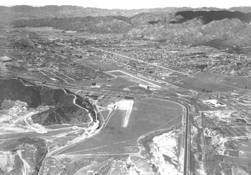
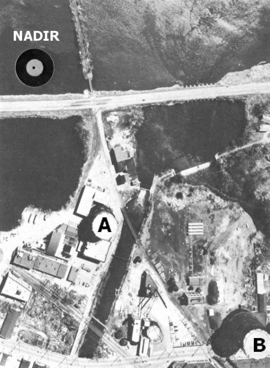
5 These types of phenomena are most evident in terrain with high local relief or significant vertical features. As stated above we will consider here three main types of problems/effects caused by specific types of distortion and displacement. These are the problems/effects associated with: 1. Lens distortion; 2. Tilt Displacement; and, 3. Topographic Displacement. Lens distortion - Small effects due to the flaws in the optical components (i.e. lens) of camera systems leading to distortions (which are typically more serious at the edges of photos). Car windows/windshields, carnival mirrors are probably the best know examples of this type of effect. These effects are radial from the principal point (making objects appear either closer to, or farther from the principal point than they actually are); and may be corrected using calibration curves. Tilt Displacement - A tilted photograph presents a slightly oblique view rather than a true vertical record. All photos have some tilt. The perfect gyro stabilization unit, like the perfect lens, has yet to be built. Tilt is caused by the rotation of the platform away from the vertical. This type of displacement typically occurs along the axis of the wings or the flight line. Tilt displacement radiates from the isocenter of the photo and causes objects to be displaced radially towards the isocenter on the upper side of the tilted photo and radially outward on the lower side. If the amount and direction of tilt are known then the photo may be rectified. Topographic Displacement - This is typically the most serious type of displacement. This displacement radiates outward from Nadir. Topographic displacement is caused by the perspective geometry of the camera and the terrain at varying elevations. Topographic displacement is not necessarily bad as it allows: 1. Stereo viewing; 2. Height measurement; and, 3. Topographic mapping. Note: From directly overhead a smokestack looks like a doughnut if there is no shadow. If the same smokestack is near the edge of the image you can see more of it's side. Tell the story of trees drown by a reservoir and the displacement pattern on the photo. The formula for topographic or height displacement on a single photo is:
6 d = r(h)/h = r(h)/(a-e) h = d(h)/r = d(a-e)/r Where: d = Radial displacement (with respect to the Nadir) n the photo at the same scale as the Nadir. r = Radial photo distance from Nadir (use PP) to the point of displacement (usually the top of the object). h = Height of the object or difference in elevation ( E) between Nadir and displaced point. H = Flying height above the base of the object (or above the Nadir in some situations). A close look at the equations involved in the calculations of relief displacement show that some important general relationships are involved. These relationships can be stated as follows: 1. There is no topographic displacement at Nadir. If r is zero, then so is d. 2. Assuming datum elevation to be at Nadir, points above the datum are displaced radially away from Nadir while points below datum are displaced radially towards Nadir.
7 Relief Displacement 3. Topographic displacement varies directly with the radial distance from the Nadir to the object. A particular elevation two inches from the Nadir will have half the displacement as that same elevation four inches from the Nadir. Overlap 4. Topographic displacement varies directly with the height of an object. A 100 ft. tree would be displaced twice as far as a 50 ft. tree the same distance from Nadir. Relief Displacement 5. Topographic displacement varies inversely with the flying height of the base of the object. As a result there is little apparent topographic displacement on space photography. The reason for small relief displacement from space is that to achieve a given scale a shorter focal length lens requires flying at a lower altitude. The effect of using short focal length lenses is to increase topographic displacement, distortion and the apparent depth of

8 the third dimension (vertical exaggeration) in stereoscopic images). To get a scale of 1: 20,000 you fly at 10,000 ft. with a six inch focal length lens; but at 20,000 ft. with a 12 inch focal length lens. Basically, then the most important cause of object displacement on aerial photography is local relief. Remember here that there are times when increased displacement can be a good thing (e.g. for height measurements). So in flat areas you may want to use a short focal length lens to achieve a given scale. From Space then you can still use extremely long lenses with little displacement. IV. Orthophotography Briefly, here there is a growing use of orthophotography today. If you remember back to our discussion of maps at the beginning of the lecture you will remember that orthographic projection depict thing in their true plan position. Basically what happens in the production of orthophotographs is that the original photographs are employ to create a stereo-model which is scanned, by very expensive (today) equipment (orthophotoscope), in very small segments; displacements are corrected and the resulting strips are merged to create a photograph that is essentially a map, actually a planimetrically accurate photomap. On an orthophoto distances, areas, and directions can all be accurately measured more easily. The U.S. Geological Survey s National Mapping Division is doing all revisions of the 1: 24,000 topographic map updates using digital orthophotography. These ortho photo maps show more detail than the older cartographic product due to the actual image background. Original & Ortho Rectified Air Photo So, the advantages here are: 1. Greater detail than a map 2. Equal planimetric accuracy But, the disadvantages are: 1. Lower resolution than the original photos
9 2. Some loss of information with loss of resolution 3. Loss of stereoscopic capability. Return to Top of Page Return to the RSCC Home Page Return to Volume 1: Table of Contents Advance to Module 7
10
11
12
13
14
15
16
17
18
19
20
21
22
23
Geometry of Aerial Photographs
 Geometry of Aerial Photographs Aerial Cameras Aerial cameras must be (details in lectures): Geometrically stable Have fast and efficient shutters Have high geometric and optical quality lenses They can
Following are the geometrical elements of the aerial photographs:
 Geometrical elements/characteristics of aerial photograph: An aerial photograph is a central or perspective projection, where the bundles of perspective rays meet at a point of origin called perspective
Basics of Photogrammetry Note#6
 Basics of Photogrammetry Note#6 Photogrammetry Art and science of making accurate measurements by means of aerial photography Analog: visual and manual analysis of aerial photographs in hard-copy format
not to be republished NCERT Introduction To Aerial Photographs Chapter 6
 Chapter 6 Introduction To Aerial Photographs Figure 6.1 Terrestrial photograph of Mussorrie town of similar features, then we have to place ourselves somewhere in the air. When we do so and look down,
Sample Copy. Not For Distribution.
 Photogrammetry, GIS & Remote Sensing Quick Reference Book i EDUCREATION PUBLISHING Shubham Vihar, Mangla, Bilaspur, Chhattisgarh - 495001 Website: www.educreation.in Copyright, 2017, S.S. Manugula, V.
NREM 345 Week 2, Material covered this week contributes to the accomplishment of the following course goal:
 NREM 345 Week 2, 2010 Reading assignment: Chapter. 4 and Sec. 5.1 to 5.2.4 Material covered this week contributes to the accomplishment of the following course goal: Goal 1: Develop the understanding and
Aerial photography: Principles. Frame capture sensors: Analog film and digital cameras
 Aerial photography: Principles Frame capture sensors: Analog film and digital cameras Overview Introduction Frame vs scanning sensors Cameras (film and digital) Photogrammetry Orthophotos Air photos are
11/25/2009 CHAPTER THREE INTRODUCTION INTRODUCTION (CONT D) THE AERIAL CAMERA: LENS PHOTOGRAPHIC SENSORS
 THE AERIAL CAMERA: LENS PHOTOGRAPHIC SENSORS") INTRODUCTION CHAPTER THREE IC SENSORS Photography means to write with light Today s meaning is often expanded to include radiation just outside the visible spectrum, i. e. ultraviolet and near infrared
INTRODUCTION CHAPTER THREE IC SENSORS Photography means to write with light Today s meaning is often expanded to include radiation just outside the visible spectrum, i. e. ultraviolet and near infrared
Relief Displacement of Vertical Features
 G 210 Lab. Relief Displacement of Vertical Features An increase in the elevation of a feature causes its position on the photograph to be displaced radially outward from the principle point. Hence, when
Photogrammetry. Lecture 4 September 7, 2005
 Photogrammetry Lecture 4 September 7, 2005 What is Photogrammetry Photogrammetry is the art and science of making accurate measurements by means of aerial photography: Analog photogrammetry (using films:
PHOTOGRAMMETRY STEREOSCOPY FLIGHT PLANNING PHOTOGRAMMETRIC DEFINITIONS GROUND CONTROL INTRODUCTION
 PHOTOGRAMMETRY STEREOSCOPY FLIGHT PLANNING PHOTOGRAMMETRIC DEFINITIONS GROUND CONTROL INTRODUCTION Before aerial photography and photogrammetry became a reliable mapping tool, planimetric and topographic
Introduction to Photogeology
 Geological Mapping 1 Academic Year 2016/2017 Introduction to Photogeology Igor Vlahović igor.vlahovic@rgn.hr Today we will say a little about basic photogeological analysis of terrain: about aerial photographs,
Principles of Photogrammetry
 Winter 2014 1 Instructor: Contact Information. Office: Room # ENE 229C. Tel: (403) 220-7105. E-mail: ahabib@ucalgary.ca Lectures (SB 148): Monday, Wednesday& Friday (10:00 a.m. 10:50 a.m.). Office Hours:
Lesson 12. Stereoscopy and Photo Preparation. Steven J. Steinberg
 Lesson 12 Stereoscopy and Photo Preparation Steven J. Steinberg Description: The lessons in this section focus on stereoscopy and photo preparation. We begin with a discussion of the principles of stereoscopy.
CEE 6100 / CSS 6600 Remote Sensing Fundamentals 1 Topic 4: Photogrammetry
 CEE 6100 / CSS 6600 Remote Sensing Fundamentals 1 PHOTOGRAMMETRY DEFINITION (adapted from Manual of Photographic Interpretation, 2 nd edition, Warren Philipson, 1997) Photogrammetry and Remote Sensing:
Lesson 4: Photogrammetry
 This work by the National Information Security and Geospatial Technologies Consortium (NISGTC), and except where otherwise Development was funded by the Department of Labor (DOL) Trade Adjustment Assistance
Photo Scale The photo scale and representative fraction may be calculated as follows: PS = f / H Variables: PS - Photo Scale, f - camera focal
 Scale Scale is the ratio of a distance on an aerial photograph to that same distance on the ground in the real world. It can be expressed in unit equivalents like 1 inch = 1,000 feet (or 12,000 inches)
2019 NYSAPLS Conf> Fundamentals of Photogrammetry for Land Surveyors
 2019 NYSAPLS Conf> Fundamentals of Photogrammetry for Land Surveyors George Southard GSKS Associates LLC Introduction George Southard: Master s Degree in Photogrammetry and Cartography 40 years working
Chapters 1 & 2. Definitions and applications Conceptual basis of photogrammetric processing
 Chapters 1 & 2 Chapter 1: Photogrammetry Definitions and applications Conceptual basis of photogrammetric processing Transition from two-dimensional imagery to three-dimensional information Automation
Content Reviewer (CR) Swati Katiyar Senior Research Fellow, Birla Institute of Scientific Research, Jaipur Language Editor (LE)
 Swati Katiyar Senior Research Fellow, Birla Institute of Scientific Research, Jaipur Language Editor (LE)") Component-I(A) - Personal Details Role Name Affiliation Principal Investigator Prof.MasoodAhsanSiddiqui Department of Geography, JamiaMilliaIslamia, New Delhi Paper Coordinator, if any Dr. M P Punia Head,
Component-I(A) - Personal Details Role Name Affiliation Principal Investigator Prof.MasoodAhsanSiddiqui Department of Geography, JamiaMilliaIslamia, New Delhi Paper Coordinator, if any Dr. M P Punia Head,
MINNESOTA DEPARTMENT OF TRANSPORTATION OFFICE OF LAND MANAGEMENT SURVEYING AND MAPPING SECTION PHOTOGRAMMETRY UNIT
 SEP. 2011 MINNESOTA DEPARTMENT OF TRANSPORTATION OFFICE OF LAND MANAGEMENT SURVEYING AND MAPPING SECTION PHOTOGRAMMETRY UNIT SPECIAL PROVISIONS FOR: GROUP 1: AERIAL PHOTOGRAPHY/PHOTOGRAMMETRIC LAB SERVICES
CHAPTER 8 AERIAL PHOTOGRAPHS
 CHAPTER 8 AERIAL PHOTOGRAPHS An aerial photograph is any photograph taken from an airborne vehicle (aircraft, drones, balloons, satellites, and so forth). The aerial photograph has many uses in military
Atmospheric interactions; Aerial Photography; Imaging systems; Intro to Spectroscopy Week #3: September 12, 2018
 GEOL 1460/2461 Ramsey Introduction/Advanced Remote Sensing Fall, 2018 Atmospheric interactions; Aerial Photography; Imaging systems; Intro to Spectroscopy Week #3: September 12, 2018 I. Quick Review from
Mapping Cameras. Chapter Three Introduction
 Chapter Three Mapping Cameras 3.1. Introduction This chapter introduces sensors used for acquiring aerial photographs. Although cameras are the oldest form of remote sensing instrument, they have changed
Photographic Interpretation Handbook, United States Forces: Section 09 Height and Depth Finding from Parallax
 University of Nebraska - Lincoln DigitalCommons@University of Nebraska - Lincoln DOD Military Intelligence U.S. Department of Defense 4-1944 Photographic Interpretation Handbook, United States Forces:
Chapter 23. Mirrors and Lenses
 Chapter 23 Mirrors and Lenses Notation for Mirrors and Lenses The object distance is the distance from the object to the mirror or lens Denoted by p The image distance is the distance from the image to
Acquisition of Aerial Photographs and/or Satellite Imagery
 Acquisition of Aerial Photographs and/or Satellite Imagery Acquisition of Aerial Photographs and/or Imagery From time to time there is considerable interest in the purchase of special-purpose photography
MONITORING RUBBLE-MOUND COASTAL STRUCTURES WITH PHOTOGRAMMETRY
 ,. CETN-III-21 2/84 MONITORING RUBBLE-MOUND COASTAL STRUCTURES WITH PHOTOGRAMMETRY INTRODUCTION: Monitoring coastal projects usually involves repeated surveys of coastal structures and/or beach profiles.
Remote Sensing. Measuring an object from a distance. For GIS, that means using photographic or satellite images to gather spatial data
 Remote Sensing Measuring an object from a distance For GIS, that means using photographic or satellite images to gather spatial data Remote Sensing measures electromagnetic energy reflected or emitted
Notation for Mirrors and Lenses. Chapter 23. Types of Images for Mirrors and Lenses. More About Images
 Notation for Mirrors and Lenses Chapter 23 Mirrors and Lenses Sections: 4, 6 Problems:, 8, 2, 25, 27, 32 The object distance is the distance from the object to the mirror or lens Denoted by p The image
Spherical Mirrors. Concave Mirror, Notation. Spherical Aberration. Image Formed by a Concave Mirror. Image Formed by a Concave Mirror 4/11/2014
 Notation for Mirrors and Lenses Chapter 23 Mirrors and Lenses The object distance is the distance from the object to the mirror or lens Denoted by p The image distance is the distance from the image to
Lab 4 - Photogrammetry
 Name: GSP 216: Introduction to Remote Sensing Introduction Lab 4 - Photogrammetry Photogrammetry is process of making measurements from photographs. In this lab we will become familiar with the basic photogrammic
Acquisition of Aerial Photographs and/or Imagery
 Acquisition of Aerial Photographs and/or Imagery Acquisition of Aerial Photographs and/or Imagery From time to time there is considerable interest in the purchase of special-purpose photography contracted
Lab #10 Digital Orthophoto Creation (Using Leica Photogrammetry Suite)
") Lab #10 Digital Orthophoto Creation (Using Leica Photogrammetry Suite) References: Leica Photogrammetry Suite Project Manager: Users Guide, Leica Geosystems LLC. Leica Photogrammetry Suite 9.2 Introduction:
Lab #10 Digital Orthophoto Creation (Using Leica Photogrammetry Suite) References: Leica Photogrammetry Suite Project Manager: Users Guide, Leica Geosystems LLC. Leica Photogrammetry Suite 9.2 Introduction:
Chapter 23. Mirrors and Lenses
 Chapter 23 Mirrors and Lenses Notation for Mirrors and Lenses The object distance is the distance from the object to the mirror or lens Denoted by p The image distance is the distance from the image to
10.2 Images Formed by Lenses SUMMARY. Refraction in Lenses. Section 10.1 Questions
 10.2 SUMMARY Refraction in Lenses Converging lenses bring parallel rays together after they are refracted. Diverging lenses cause parallel rays to move apart after they are refracted. Rays are refracted
High Resolution Sensor Test Comparison with SPOT, KFA1000, KVR1000, IRS-1C and DPA in Lower Saxony
 High Resolution Sensor Test Comparison with SPOT, KFA1000, KVR1000, IRS-1C and DPA in Lower Saxony K. Jacobsen, G. Konecny, H. Wegmann Abstract The Institute for Photogrammetry and Engineering Surveys
Project Planning and Cost Estimating
 CHAPTER 17 Project Planning and Cost Estimating 17.1 INTRODUCTION Previous chapters have outlined and detailed technical aspects of photogrammetry. The basic tasks and equipment required to create various
Remote sensing image correction
 Remote sensing image correction Introductory readings remote sensing http://www.microimages.com/documentation/tutorials/introrse.pdf 1 Preprocessing Digital Image Processing of satellite images can be
EXAMPLES OF TOPOGRAPHIC MAPS PRODUCED FROM SPACE AND ACHIEVED ACCURACY CARAVAN Workshop on Mapping from Space, Phnom Penh, June 2000
 EXAMPLES OF TOPOGRAPHIC MAPS PRODUCED FROM SPACE AND ACHIEVED ACCURACY CARAVAN Workshop on Mapping from Space, Phnom Penh, June 2000 Jacobsen, Karsten University of Hannover Email: karsten@ipi.uni-hannover.de
Chapter 23. Mirrors and Lenses
 Chapter 23 Mirrors and Lenses Mirrors and Lenses The development of mirrors and lenses aided the progress of science. It led to the microscopes and telescopes. Allowed the study of objects from microbes
Waves & Oscillations
 Physics 42200 Waves & Oscillations Lecture 33 Geometric Optics Spring 2013 Semester Matthew Jones Aberrations We have continued to make approximations: Paraxial rays Spherical lenses Index of refraction
COPYRIGHTED MATERIAL. Overview
 In normal experience, our eyes are constantly in motion, roving over and around objects and through ever-changing environments. Through this constant scanning, we build up experience data, which is manipulated
Chapter 23. Geometrical Optics: Mirrors and Lenses and other Instruments
 Chapter 23 Geometrical Optics: Mirrors and Lenses and other Instruments HITT 1 You stand two feet away from a plane mirror. How far is it from you to your image? a. 2.0 ft b. 3.0 ft c. 4.0 ft d. 5.0 ft
COPYRIGHTED MATERIAL OVERVIEW 1
 OVERVIEW 1 In normal experience, our eyes are constantly in motion, roving over and around objects and through ever-changing environments. Through this constant scanning, we build up experiential data,
AERIAL PHOTOGRAPHS CHAPTER 8
 CHAPTER 8 AERIAL PHOTOGRAPHS An aerial photograph is any photograph taken from an airborne vehicle (aircraft, drones, balloons) satellites, and so forth). The aerial photograph has many uses in military
Phase One 190MP Aerial System
 White Paper Phase One 190MP Aerial System Introduction Phase One Industrial s 100MP medium format aerial camera systems have earned a worldwide reputation for its high performance. They are commonly used
LAB 2: AERIAL PHOTOGRAPHY AND PHOTOGRAMMETRY PART 1: INTERPRETATION OF AERIAL PHOTOGRAPHY
 E&ES 328 Remote Sensing Laboratory LAB 2: AERIAL PHOTOGRAPHY AND PHOTOGRAMMETRY Due February 22, 2012 PART 1: INTERPRETATION OF AERIAL PHOTOGRAPHY Some of the first aerial photography, employed during
HD aerial video for coastal zone ecological mapping
 HD aerial video for coastal zone ecological mapping Albert K. Chong University of Otago, Dunedin, New Zealand Phone: +64 3 479-7587 Fax: +64 3 479-7586 Email: albert.chong@surveying.otago.ac.nz Presented
An Introduction to Geomatics. Prepared by: Dr. Maher A. El-Hallaq خاص بطلبة مساق مقدمة في علم. Associate Professor of Surveying IUG
 An Introduction to Geomatics خاص بطلبة مساق مقدمة في علم الجيوماتكس Prepared by: Dr. Maher A. El-Hallaq Associate Professor of Surveying IUG 1 Airborne Imagery Dr. Maher A. El-Hallaq Associate Professor
SFR 406 Spring 2015 Lecture 7 Notes Film Types and Filters
 SFR 406 Spring 2015 Lecture 7 Notes Film Types and Filters 1. Film Resolution Introduction Resolution relates to the smallest size features that can be detected on the film. The resolving power is a related
Remote Sensing. Ch. 3 Microwaves (Part 1 of 2)
") Remote Sensing Ch. 3 Microwaves (Part 1 of 2) 3.1 Introduction 3.2 Radar Basics 3.3 Viewing Geometry and Spatial Resolution 3.4 Radar Image Distortions 3.1 Introduction Microwave (1cm to 1m in wavelength)
Remote Sensing Ch. 3 Microwaves (Part 1 of 2) 3.1 Introduction 3.2 Radar Basics 3.3 Viewing Geometry and Spatial Resolution 3.4 Radar Image Distortions 3.1 Introduction Microwave (1cm to 1m in wavelength)
Unmanned Aerial Vehicle Data Acquisition for Damage Assessment in. Hurricane Events
 Unmanned Aerial Vehicle Data Acquisition for Damage Assessment in Hurricane Events Stuart M. Adams a Carol J. Friedland b and Marc L. Levitan c ABSTRACT This paper examines techniques for data collection
CALIBRATION OF OPTICAL SATELLITE SENSORS
 CALIBRATION OF OPTICAL SATELLITE SENSORS KARSTEN JACOBSEN University of Hannover Institute of Photogrammetry and Geoinformation Nienburger Str. 1, D-30167 Hannover, Germany jacobsen@ipi.uni-hannover.de
What is Photogrammetry
 Photogrammetry What is Photogrammetry Photogrammetry is the art and science of making accurate measurements by means of aerial photography: Analog photogrammetry (using films: hard-copy photos) Digital
Mirrors and Lenses. Images can be formed by reflection from mirrors. Images can be formed by refraction through lenses.
 Mirrors and Lenses Images can be formed by reflection from mirrors. Images can be formed by refraction through lenses. Notation for Mirrors and Lenses The object distance is the distance from the object
Chapter 18 Optical Elements
 Chapter 18 Optical Elements GOALS When you have mastered the content of this chapter, you will be able to achieve the following goals: Definitions Define each of the following terms and use it in an operational
What is the scale of this vertical aerial photo? Small or large scale??
 What is the scale o this vertical aerial photo? Small or large scale?? SCALE what does it mean? the relationship between linear distance on a photo (or a map) and the corresponding actual distance on the
CSI: Rombalds Moor Photogrammetry Photography
 Photogrammetry Photography Photogrammetry Training 26 th March 10:00 Welcome Presentation image capture Practice 12:30 13:15 Lunch More practice 16:00 (ish) Finish or earlier What is photogrammetry 'photo'
Perspective. Announcement: CS4450/5450. CS 4620 Lecture 3. Will be MW 8:40 9:55 How many can make the new time?
 Perspective CS 4620 Lecture 3 1 2 Announcement: CS4450/5450 Will be MW 8:40 9:55 How many can make the new time? 3 4 History of projection Ancient times: Greeks wrote about laws of perspective Renaissance:
RPAS Photogrammetric Mapping Workflow and Accuracy
 RPAS Photogrammetric Mapping Workflow and Accuracy Dr Yincai Zhou & Dr Craig Roberts Surveying and Geospatial Engineering School of Civil and Environmental Engineering, UNSW Background RPAS category and
MSB Imagery Program FAQ v1
 MSB Imagery Program FAQ v1 (F)requently (A)sked (Q)uestions 9/22/2016 This document is intended to answer commonly asked questions related to the MSB Recurring Aerial Imagery Program. Table of Contents
Application of GIS to Fast Track Planning and Monitoring of Development Agenda
 Application of GIS to Fast Track Planning and Monitoring of Development Agenda Radiometric, Atmospheric & Geometric Preprocessing of Optical Remote Sensing 13 17 June 2018 Outline 1. Why pre-process remotely
NRMT 2270, Photogrammetry/Remote Sensing. Lecture 4
 NRMT 2270, Photogrammetry/Remote Sensing Lecture 4 Cameras. Lenses. Photo Scale. Principles of Aerial Photography. Principle and Conjugate Principal Points. Vertical and Oblique Aerial photos. Stereo Viewing.
Leica ADS80 - Digital Airborne Imaging Solution NAIP, Salt Lake City 4 December 2008
 Luzern, Switzerland, acquired at 5 cm GSD, 2008. Leica ADS80 - Digital Airborne Imaging Solution NAIP, Salt Lake City 4 December 2008 Shawn Slade, Doug Flint and Ruedi Wagner Leica Geosystems AG, Airborne
Structure from Motion (SfM) Photogrammetry Field Methods Manual for Students
 Photogrammetry Field Methods Manual for Students") Structure from Motion (SfM) Photogrammetry Field Methods Manual for Students Written by Katherine Shervais (UNAVCO) Introduction to SfM for Field Education The purpose of the Analyzing High Resolution
Structure from Motion (SfM) Photogrammetry Field Methods Manual for Students Written by Katherine Shervais (UNAVCO) Introduction to SfM for Field Education The purpose of the Analyzing High Resolution
GEOMETRICAL OPTICS Practical 1. Part I. BASIC ELEMENTS AND METHODS FOR CHARACTERIZATION OF OPTICAL SYSTEMS
 GEOMETRICAL OPTICS Practical 1. Part I. BASIC ELEMENTS AND METHODS FOR CHARACTERIZATION OF OPTICAL SYSTEMS Equipment and accessories: an optical bench with a scale, an incandescent lamp, matte, a set of
CALIBRATION OF IMAGING SATELLITE SENSORS
 CALIBRATION OF IMAGING SATELLITE SENSORS Jacobsen, K. Institute of Photogrammetry and GeoInformation, University of Hannover jacobsen@ipi.uni-hannover.de KEY WORDS: imaging satellites, geometry, calibration
ECEN 4606, UNDERGRADUATE OPTICS LAB
 ECEN 4606, UNDERGRADUATE OPTICS LAB Lab 2: Imaging 1 the Telescope Original Version: Prof. McLeod SUMMARY: In this lab you will become familiar with the use of one or more lenses to create images of distant
UltraCam and UltraMap Towards All in One Solution by Photogrammetry
 Photogrammetric Week '11 Dieter Fritsch (Ed.) Wichmann/VDE Verlag, Belin & Offenbach, 2011 Wiechert, Gruber 33 UltraCam and UltraMap Towards All in One Solution by Photogrammetry ALEXANDER WIECHERT, MICHAEL
VERTICAL AERIAL PHOTOGRAPHY
 VERTICAL AERIAL PHOTOGRAPHY Mike Craig Cooperative Research Centre for Landscape Environments and Mineral Exploration, Geoscience Australia. PO Box 378, Canberra, ACT 2601. E-mail: mike.craig@ga.gov.au
Geometrical Optics. Have you ever entered an unfamiliar room in which one wall was covered with a
 Return to Table of Contents HAPTER24 C. Geometrical Optics A mirror now used in the Hubble space telescope Have you ever entered an unfamiliar room in which one wall was covered with a mirror and thought
PHYSICS 289 Experiment 8 Fall Geometric Optics II Thin Lenses
 PHYSICS 289 Experiment 8 Fall 2005 Geometric Optics II Thin Lenses Please look at the chapter on lenses in your text before this lab experiment. Please submit a short lab report which includes answers
Ch 24. Geometric Optics
 text concept Ch 24. Geometric Optics Fig. 24 3 A point source of light P and its image P, in a plane mirror. Angle of incidence =angle of reflection. text. Fig. 24 4 The blue dashed line through object
Large Scale Photogrammetric Maps for Land Planning
 Large Scale Photogrammetric Maps for Land Planning A lva F. W arren Clyde E. Williams & Associates, Inc. South Bend, Indiana Introduction It is my purpose to give a brief explanation of the method of making
UNIT SUMMARY: Electromagnetic Spectrum, Color, & Light Name: Date:
 UNIT SUMMARY: Electromagnetic Spectrum, Color, & Light Name: Date: Topics covered in the unit: 1. Electromagnetic Spectrum a. Order of classifications and respective wavelengths b. requency, wavelength,
FOR 474: Forest Inventory. FOR 474: Forest Inventory. Why do we Care About Forest Sampling?
 FOR 474: Forest Inventory 1. Advanced Forest Inventory The Need for Forest Sampling Brief Intro to Remote Sensing and GIS Readings: FOR 474: Forest Inventory Related Courses! FOR 274: Forest Measurements
Introduction to Photogrammetry
 Introduction to Photogrammetry Presented By: Sasanka Madawalagama Geoinformatics Center Asian Institute of Technology Thailand www.geoinfo.ait.asia Content Introduction to photogrammetry 2D to 3D Drones
ANALYSIS OF SRTM HEIGHT MODELS
 ANALYSIS OF SRTM HEIGHT MODELS Sefercik, U. *, Jacobsen, K.** * Karaelmas University, Zonguldak, Turkey, ugsefercik@hotmail.com **Institute of Photogrammetry and GeoInformation, University of Hannover,
Lecture 2: Geometrical Optics. Geometrical Approximation. Lenses. Mirrors. Optical Systems. Images and Pupils. Aberrations.
 Lecture 2: Geometrical Optics Outline 1 Geometrical Approximation 2 Lenses 3 Mirrors 4 Optical Systems 5 Images and Pupils 6 Aberrations Christoph U. Keller, Leiden Observatory, keller@strw.leidenuniv.nl
BASED on the comments of several members of the American Society of
 SYMPOSIUM ON PHOTOGRAMMETRIC TECHNIQUES-COMMERCIAL OPERATIONS 349 The time of development is controlled by altering the speed of the motor and, under ordinary circumstances, we are able to process three
Application of GIS for earthquake hazard and risk assessment: Kathmandu, Nepal. Part 2: Data preparation GIS CASE STUDY
 GIS CASE STUDY Application of GIS for earthquake hazard and risk assessment: Kathmandu, Nepal Part 2: Data preparation Cees van Westen (E-mail : westen@itc.nl) Siefko Slob (E-mail: Slob@itc.nl) Lorena
Lab 11: Lenses and Ray Tracing
 Name: Lab 11: Lenses and Ray Tracing Group Members: Date: TA s Name: Materials: Ray box, two different converging lenses, one diverging lens, screen, lighted object, three stands, meter stick, two letter
Remote Sensing is the observation of the Earth from satellites or aircrafts.
 Remote Sensing? Remote Sensing is the observation of the Earth from satellites or aircrafts. Sensors mounted on these platforms capture images of the Earth that reveal features may or may not apparent
Chapter 29/30. Wave Fronts and Rays. Refraction of Sound. Dispersion in a Prism. Index of Refraction. Refraction and Lenses
 Chapter 29/30 Refraction and Lenses Refraction Refraction the bending of waves as they pass from one medium into another. Caused by a change in the average speed of light. Analogy A car that drives off
HIGH RESOLUTION COLOR IMAGERY FOR ORTHOMAPS AND REMOTE SENSING. Author: Peter Fricker Director Product Management Image Sensors
 HIGH RESOLUTION COLOR IMAGERY FOR ORTHOMAPS AND REMOTE SENSING Author: Peter Fricker Director Product Management Image Sensors Co-Author: Tauno Saks Product Manager Airborne Data Acquisition Leica Geosystems
Image Fusion. Pan Sharpening. Pan Sharpening. Pan Sharpening: ENVI. Multi-spectral and PAN. Magsud Mehdiyev Geoinfomatics Center, AIT
 1 Image Fusion Sensor Merging Magsud Mehdiyev Geoinfomatics Center, AIT Image Fusion is a combination of two or more different images to form a new image by using certain algorithms. ( Pohl et al 1998)
28 Thin Lenses: Ray Tracing
 28 Thin Lenses: Ray Tracing A lens is a piece of transparent material whose surfaces have been shaped so that, when the lens is in another transparent material (call it medium 0), light traveling in medium
746A27 Remote Sensing and GIS
 746A27 Remote Sensing and GIS Lecture 1 Concepts of remote sensing and Basic principle of Photogrammetry Chandan Roy Guest Lecturer Department of Computer and Information Science Linköping University What
Govt. Engineering College Jhalawar Model Question Paper Subject- Remote Sensing & GIS
 Govt. Engineering College Jhalawar Model Question Paper Subject- Remote Sensing & GIS Time: Max. Marks: Q1. What is remote Sensing? Explain the basic components of a Remote Sensing system. Q2. What is
Aperture and Digi scoping. Thoughts on the value of the aperture of a scope digital camera combination.
 Aperture and Digi scoping. Thoughts on the value of the aperture of a scope digital camera combination. Before entering the heart of the matter, let s do a few reminders. 1. Entrance pupil. It is the image
PHYSICS FOR THE IB DIPLOMA CAMBRIDGE UNIVERSITY PRESS
 Option C Imaging C Introduction to imaging Learning objectives In this section we discuss the formation of images by lenses and mirrors. We will learn how to construct images graphically as well as algebraically.
Lens Principal and Nodal Points
 Lens Principal and Nodal Points Douglas A. Kerr, P.E. Issue 3 January 21, 2004 ABSTRACT In discussions of photographic lenses, we often hear of the importance of the principal points and nodal points of
RADIO WAVE PROPAGATION
 CHAPTER 2 RADIO WAVE PROPAGATION Radio direction finding (RDF) deals with the direction of arrival of radio waves. Therefore, it is necessary to understand the basic principles involved in the propagation
Lecture 2: Geometrical Optics. Geometrical Approximation. Lenses. Mirrors. Optical Systems. Images and Pupils. Aberrations.
 Lecture 2: Geometrical Optics Outline 1 Geometrical Approximation 2 Lenses 3 Mirrors 4 Optical Systems 5 Images and Pupils 6 Aberrations Christoph U. Keller, Leiden Observatory, keller@strw.leidenuniv.nl
Outline Remote Sensing Defined Resolution Electromagnetic Energy (EMR) Types Interpretation Applications
 Types Interpretation Applications") Introduction to Remote Sensing Outline Remote Sensing Defined Resolution Electromagnetic Energy (EMR) Types Interpretation Applications Remote Sensing Defined Remote Sensing is: The art and science of
Introduction to Remote Sensing Outline Remote Sensing Defined Resolution Electromagnetic Energy (EMR) Types Interpretation Applications Remote Sensing Defined Remote Sensing is: The art and science of
Chapter 36. Image Formation
 Chapter 36 Image Formation Real and Virtual Images Real images can be displayed on screens Virtual Images can not be displayed onto screens. Focal Length& Radius of Curvature When the object is very far
Assignment X Light. Reflection and refraction of light. (a) Angle of incidence (b) Angle of reflection (c) principle axis
 Angle of incidence (b) Angle of reflection (c) principle axis") Assignment X Light Reflection of Light: Reflection and refraction of light. 1. What is light and define the duality of light? 2. Write five characteristics of light. 3. Explain the following terms (a)
Assignment X Light Reflection of Light: Reflection and refraction of light. 1. What is light and define the duality of light? 2. Write five characteristics of light. 3. Explain the following terms (a)
History of projection. Perspective. History of projection. Plane projection in drawing
 History of projection Ancient times: Greeks wrote about laws of perspective Renaissance: perspective is adopted by artists Perspective CS 4620 Lecture 3 Duccio c. 1308 1 2 History of projection Plane projection
Waves & Oscillations
 Physics 42200 Waves & Oscillations Lecture 27 Geometric Optics Spring 205 Semester Matthew Jones Sign Conventions > + = Convex surface: is positive for objects on the incident-light side is positive for