Introduction to Photogrammetry
|
|
|
- Neal Andrews
- 5 years ago
- Views:
Transcription


1 Introduction to Photogrammetry Presented By: Sasanka Madawalagama Geoinformatics Center Asian Institute of Technology Thailand
2 Content Introduction to photogrammetry 2D to 3D Drones for mapping how it works Cameras Cameras for drones Image formation Elements of camera Lens distortions Illuminance, Aperture and Depth of field Images Photogrammetric processing Flight planning Photogrammetric GCPs 2
3 Photogrammetry Photo - light gramma - something drawn metrein - measure Photogrammetry = measuring with photographs Objective is Inverse the process of photography (i.e. reconstruction of the object space from image space). Results can be, Topographical/Planimetric/Thematic maps Coordinates of the required object points Rectified Photos 3
4 From Object to Image 4
5 Inverted Mapping 5

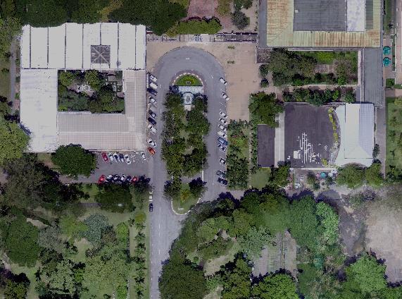
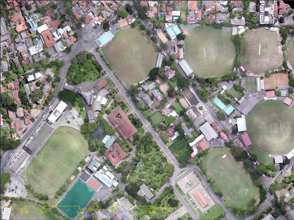
6 2D 3D Why? Can you used aerial photograph as a map directly? Single Point Perspective The photo scale is different at the tops of the buildings than at the street level. The tops of the building are displaced radially outward relative to their location at the center. 6

7 2D 3D Why? Can you used aerial photograph as a map directly? 7
8 2D 3D Why? Can you used aerial photograph as a map directly? Relief Displacement 8

9 How to prepare maps from Aerial Photographs? 3D Real World Central Projection Aerial Photo -2D Orthogonal Projection Map -2D Ground Model -3D 9
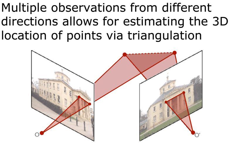
10 2D 3D 10
11 2D 3D 11
12 2D 3D 12
13 13
 = Projection Matrix x World Coordinates (3D) Camera Matrix Projection Matrix (P)")
14 2D 3D Map 2D to 3D Only With Photographs taken from Calibrated/Non Calibrated Camera Photo Coordinates (2D) = Projection Matrix x World Coordinates (3D) Camera Matrix Projection Matrix (P) 11 DOF 14

15 Orthoimages 15

16 Orthoimages 16
17 Why Photogrammetry? 17

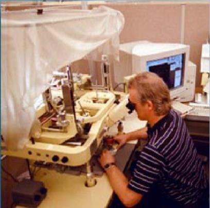

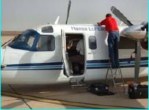
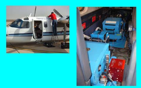
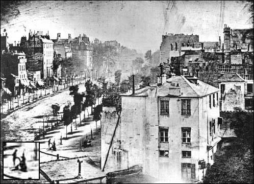
18 Evolution of Photogrammetry 18

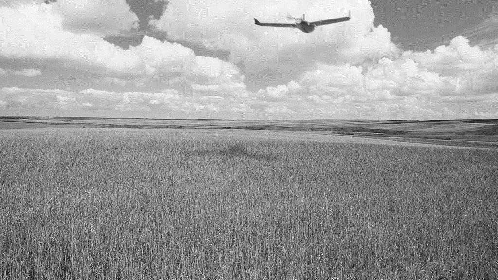
19 UAVs in Mapping Main Benefits Economical - up to 90% compared to traditional methods Easy to Fly - Ready to go system with automated flight planning Accuracy - High accurate products Very high resolution areal imagery in your hands Millions of data points in one short flight Timescale - Comparatively reduce the time spent collecting accurate data. Operational in hazardous & hard-to-reach areas
 Need specific")


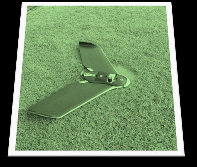
20 Survey Grade Drones vs Consumer Grade Drones Specifically Designed for Mapping Not much popular (yet) Need specific knowledge to operate Expensive Less expensive Designed for Consumer Applications - Photography, Hobby Very popular among the community Simple operation Equipped with GNSS and IMU Able to perform high accurate 3D mapping Equipped with GNSS and IMU Has great potential to use in mapping sensefly ebee Trimble UX5 DJI Phantom 3 DJI Phantom 4 Parrot BeBop
21 Drones for Mapping How it Works Drone Platform to carry imaging sensor through accurate flight path. Camera Captures overlapping images while in motion Algorithm Computer Vision + Photogrammetry Extracts geometry through matches of thousands of keypoints for generating accurate maps and 3D models. 21

22 Drones for Mapping How it Works Drone Platform to carry imaging sensor through accurate flight path. Camera Captures overlapping images while in motion Algorithm Computer Vision + Photogrammetry Extracts geometry through matches of thousands of keypoints for generating accurate maps and 3D models. 22
23 Camera The most fundamental device in the field of photogrammetry what is a camera? A lightproof chamber or box in which the image of an exterior object is projected upon a sensitized plate or film, through an opening usually equipped with a lens or lenses, shutter, and variable aperture. Manual of Photogrammetry A camera is an optical instrument for recording or capturing images, which may be stored locally, transmitted to another location, or both. Wiki 23

24 Cameras to Measure Directions 24

25 Consumer Cameras 25


26 Aerial Mapping Cameras 26

27 Aerial Mapping Cameras 27


 Sony")

28 Cameras for Drones Consumer grade cameras Point and shoot cameras Mirrorless cameras DSLR (heavy payload; not much conventional) Sony WX Default camera for ebee Sony A6000 Canon EOS 5D 28
 3 axis gimbal stabilization")
29 Cameras for Drones Cameras Designed for Drones DJI FC300X default with phantom 3 professional (built in) 3 axis gimbal stabilization 29


30 Cameras for Drones Cameras Designed for Drones 30

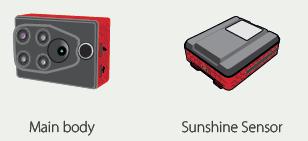
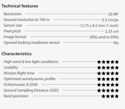
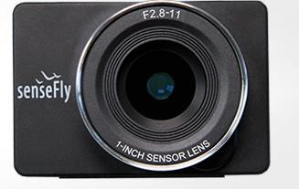
31 Cameras for Drones Parrot Sequoia ts/brochures/sequoia_specifications_2016_sensefly.pdf 31
32 Cameras for Drones Parrot Sequoia 32

33 Cameras for Drones Parrot Sequoia 33
34 Image Formation Put a piece of film in front of an object Do we get a reasonable image? 34
35 Image Formation Add a barrier to block off most of the rays This reduces blurring The opening is known as the aperture How does this transform the image? 35
36 Pinhole Camera Pinhole camera is a simple model to approximate the imaging process If we treat pinhole as a point, only one ray from any given point can enter the camera 36
37 Pinhole Camera Model Small hole: sharp image but requires large exposure times Large hole: short exposure times but blurry images Solution: replace pinhole by lenses 37
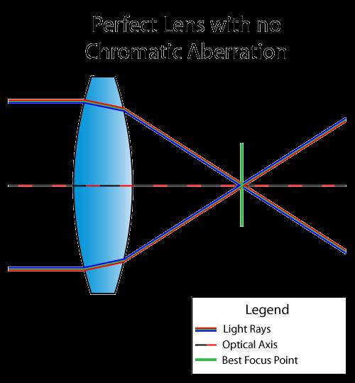
38 Lens Approximates the Pinhole A lens is only an approximation of the pinhole camera model The corresponding point on the object and in the image and the center of the lens should lie on one line The further away a beam passes the center of the lens, the larger the error Use of an aperture to limit the error (trade off between the usable light and price of the lens) 38

39 Elements of Camera 39


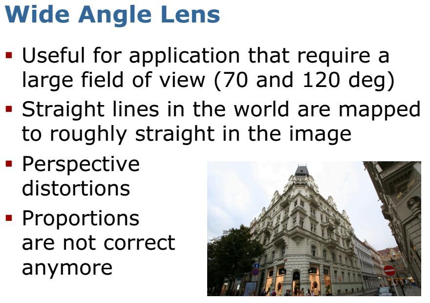
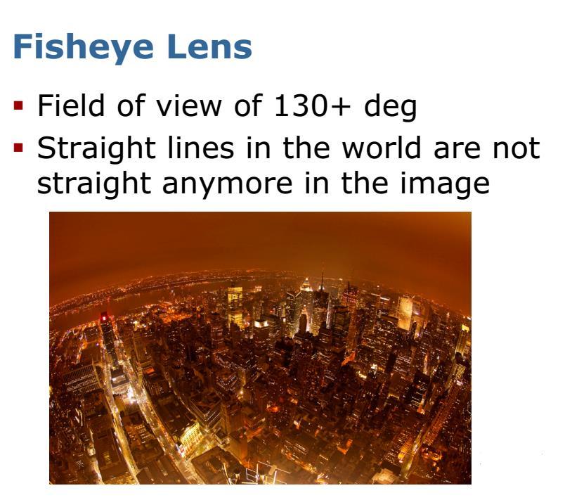
40 Lenses Goal of Lens is to obtain images that are not distorted sharp contrast intensive The choice of the lens depends on field of view distance to the object amount of available light price 40
41 41
42 Assumptions Made in the Pinhole Camera/Thin Lens 1. All rays from the object point intersect in a single point 2. All image points lie on a plane 3. The ray from the object point to the image point is a straight line Often these assumption do not hold and leads to imperfect images 42
43 Lens Distortions and Aberrations It is impossible for a single lens to produce a perfect image; blurring, or degrade the sharpness of the image, are termed aberrations. Lens distortions, on the other hand, do not degrade image quality but deteriorate the geometric quality (or positional accuracy) 43

: Typically, two coefficients are sufficient for")
44 Lens Distortions - Radial Distortions Radial distortion occurs when light rays bend more near the edges of a lens than they do at its optical center. The smaller the lens, the greater the distortion. The radial distortion coefficients model this type of distortion. The distorted points are denoted as (x distorted, y distorted ): Typically, two coefficients are sufficient for calibration. For severe distortion, such as in wide-angle lenses, 3 coefficients are selected including k 3. 44

45 Lens Distortions - Radial Distortions 45

46 Lens Distortions - Tangential Distortions Tangential distortion occurs when the lens and the image plane are not parallel. The tangential distortion coefficients model this type of distortion. 46
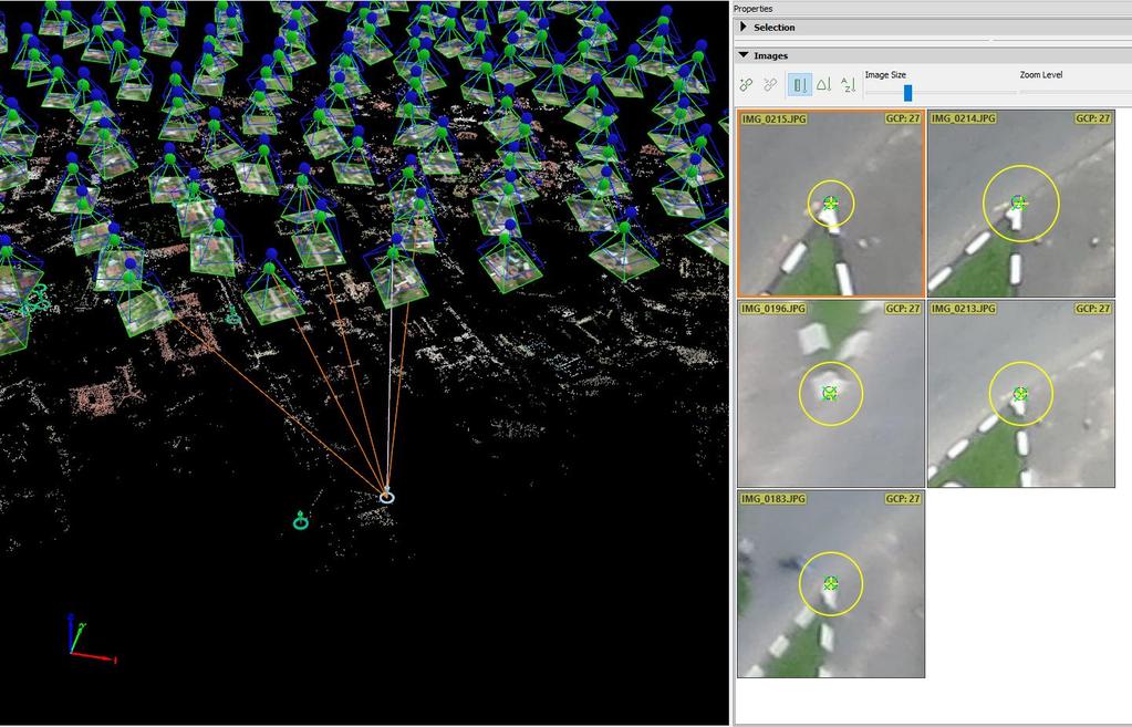
47 Camera calibration Required for an exact and precise object reconstruction Determination of correct interior orientation parameters Compensation of lens distortions and image sensor errors Useful also for valuation of the performances of lenses evaluation of the stability of camera Parameters involved: - principal point position focal length (camera constant) radial and decentering distortion terms to correct pixel size and shape (scale and shear) 47
48 Aberrations 48

49 Illuminance Brightness or amount of light received per unit area proportional to the amount of light passing through the lens opening during exposure proportional to the d 2 inversely proportional to the square of distance from the aperture. proportional to 1/i 2 49
50 Illuminance illuminance is proportional to d 2 /f 2. The square root of this term is called the brightness factor inverse expression of illuminance and is the very common term f-stop, also called f-number As the aperture increases, f-stop numbers decrease and illuminance increases, thus requiring less exposure time, i.e., faster shutter speeds. 50

51 Aperture and Depth-of-Field The aperture controls the amount of light on the sensor chip and the depth-offield Depth-of-field refers to the range of distance that appears acceptably sharp 51

52 Aperture and Depth-of-Field 52
53 Aperture and Shutter Speed for Drone Imagery Flying Height > focal Length High shutter speed low motion blur (need to have enough light) Small aperture (high f number) High depth of field (need to have adequate light) Shutter Speed f number Let the camera to take care ISO 53


54 Sensor The image sensor converts photons to intensity values Array of light-sensitive cells Two main types of sensors CCD: charge-coupled device (lower noise, more expensive, global shutter) CMOS: complementary metal oxide on silicon (higher noise, cheaper, rolling shutter) 54
55 Development of Camera The remarkable success of photogrammetry in recent years is due in large part to the progress that has been made in developing precision cameras. perfection of lenses of extremely high resolving power negligible distortion 55

56 Drones for Mapping How it Works Drone Platform to carry imaging sensor through accurate flight path. Camera Captures overlapping images while in motion Algorithm Computer Vision + Photogrammetry Extracts geometry through matches of thousands of keypoints for generating accurate maps and 3D models. 56


57 Images A digital image is a computer-compatible pictorial rendition in which the image is divided into a fine grid of picture elements, or pixels. In fact consists of an array of integers, often referred to as digital numbers, each quantifying the gray level, or degree of darkness, at a particular element. 57
58 Images 58
59 General Workflow of Modern Sfm Images Sparse Reconstruction Determine the Projection Matrix which is combination of Camera Matrix (by Camera calibration or Auto Calibration) & Exterior Orientation Matrix (by Feature Matching) Dense Reconstruction Using determined projection matrix for every selected image build dense point cloud 3D Model Build the Surface All are Black Box Processes But make our life easy. 59

60 Flight Planning 60
61 Why flight planning is important in the overall photogrammetric project? How the flight should be carried out to obtain the products in required accuracy Gives optimum specifications for a project, can be prepared only after careful consideration of all the many variables which influence aerial photography. In many areas, period of time that are acceptable for aerial photography are limited by weather & ground cover conditions which are related to seasons of the year. Proper Planning = No waste of money and time 61

62 Start with the END in mind Clear understanding about what exactly needed to be produced How the resulting data is going to be used: ex. Planning, Monitoring, Validating, supporting other data, etc.
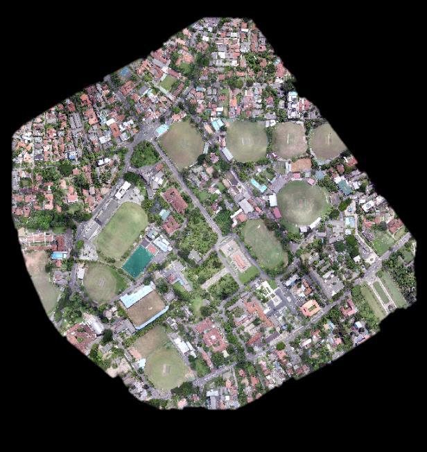

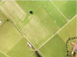
63 Orthoimage Resolution: 5 cm
64 Orthoimage An Orthoimage is generally a photo map which is geometrically corrected so that the scale is uniform. Orthoimages can be directly used for 2D measurements for calculating distances, areas and be used in Geographic Information Systems.
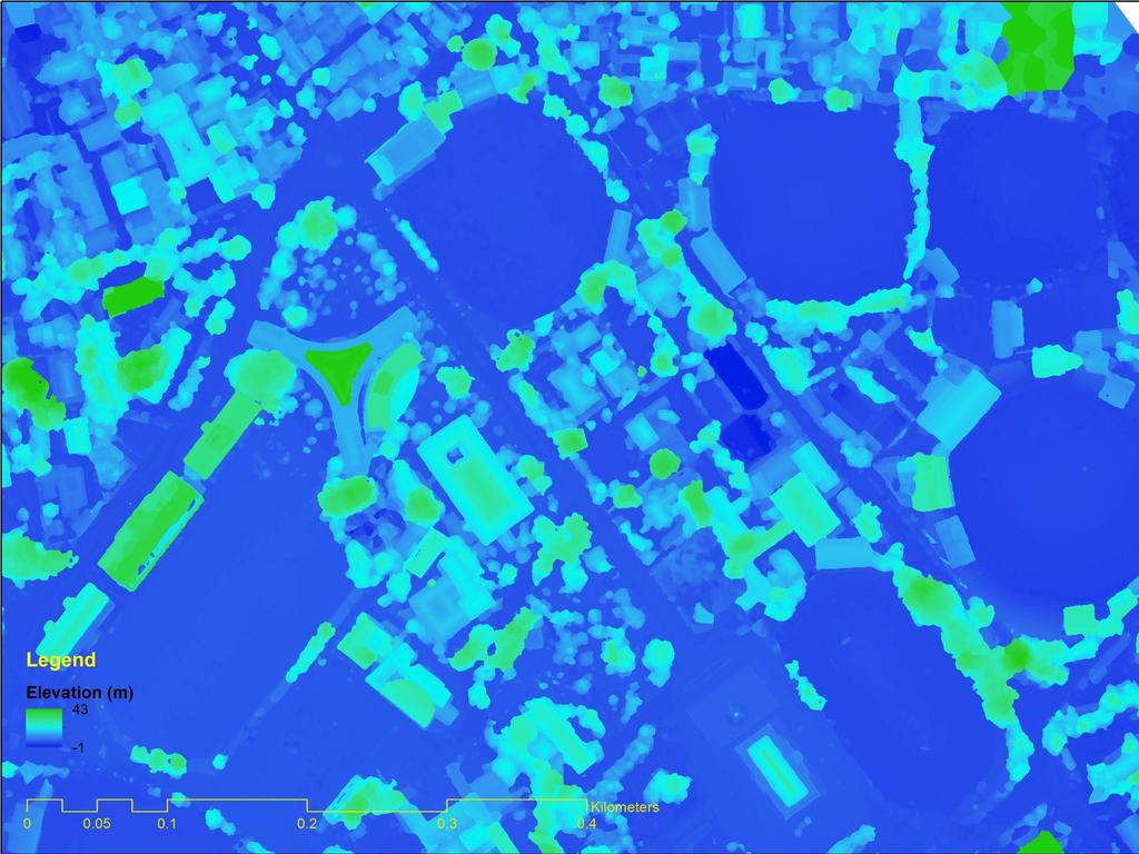
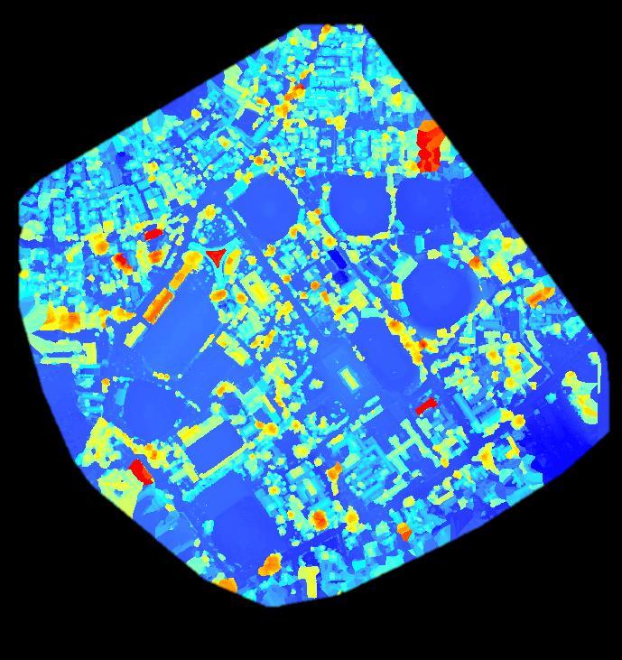
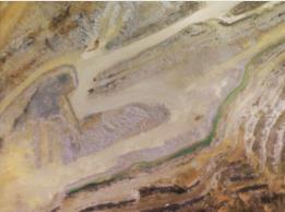
65 DSM


66 DSM A Digital Surface Model or DSM is digital 3D representation of an area by elevation. Each pixel of the raster image is assigned to represent the elevation of the location at the relevant pixel.
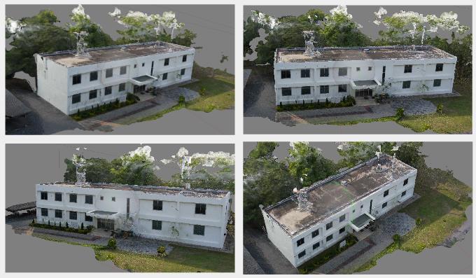
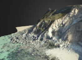
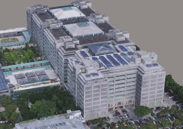
67 3D Model
68 3D Model 3D models represent a physical body using a collection of points in 3D space, connected by various geometric entities such as triangles, lines creating a mesh. These models are useful in 3D measurements, volumetric calculations, 3D graphics etc. The model is made more realistic by projecting the texture to the mesh.
69 Factors to be considered when planning a flight mission: Purpose of the project Layout of the area (a flight map) Direction of fight lines The type of the camera to be used Time of year/day Weather condition Time schedule External condition (cost, etc) A scale of the photography Forward & side overlaps Flying height Tilt & drift tolerance etc. 69
70 Weather & Seasonal considerations Cloud conditions, For drones; Good cloud cover with adequate lighting is preferred as clouds provide even distribution of sun light ideally < 10% for traditional aerial mapping Minimize Shadows 11 AM to 1PM is the ideal time Seasonal Effects ex: Leaf-off: spring/fall when deciduous tree leaves are off and ground free of snow used for topographic/soils mapping, terrain/landform interpretation Leaf-on: summer when deciduous trees are leafed out or late fall when various tree species may be identified by foliage colour used for vegetation analyses 70
71 Scale considerations What is the minimum mapping unit/ Resolution or size of smallest object that you want resolved and mapped? What is the ground coverage desired for an individual photo? How large of a study area to be covered? Resolution is function of flying height and camera focal length 71
72 Exercise Calculate the appropriate flying height for phantom 3 professional drone to obtain 5 cm/px ground sampling distance Guide Its simple projective geometry - very easy ;) All required parameters of the drone: pro/info#specs 72
73 Flight Alignment When an area is covered by vertical aerial photography, the photographs are usually taken along a series of parallel passes, called flight strips. Flight lines are planned to be parallel For maximum aircraft efficiency, they should be parallel to the long axis of the study area (minimize aircraft turns). Crab or drift should be minimized Tilt, 2-3 o for any single photo, average < 1 o for entire project for general mapping 73

74 Flight Alignment 74
75 Flight Alignment Highly dependent on your application Ex: 3D modelling 75
76 Flight Alignment 3D Mapping In general, ortho-photo and DSM made by UAV imagery are made to represents the top most surface. UAV flight plan is designed accordingly to represent the top most surface with high geometric accuracy. But in some urban/semi urban areas important features (roads, foot paths, buildings) are hidden by tree canopy or some other features. study is carried out to find out a methodology to extract such hidden features up to acceptable extent by 3D model obtained from UAV imagery using photogrammetric techniques. 76

77 Case study in AIT Coverage area : km² Flight Parameters Flying height : 100m AGL GSD : 4.9 cm/pix Overlap (Side & Forward) : 80% No of control points : 5 No of check points : 3 77

78 Case 1 : General Case near vertical photos; 1 regular grid In general case, near vertical photographs (tilt angle < 3deg) is used to generate orthoimage and DSM because of high geometric quality of such images. Near vertical images only represent accurate 2.5D model of the scene as it lacks details to representation of full 3D model. Covered features are hard to be identified. 78
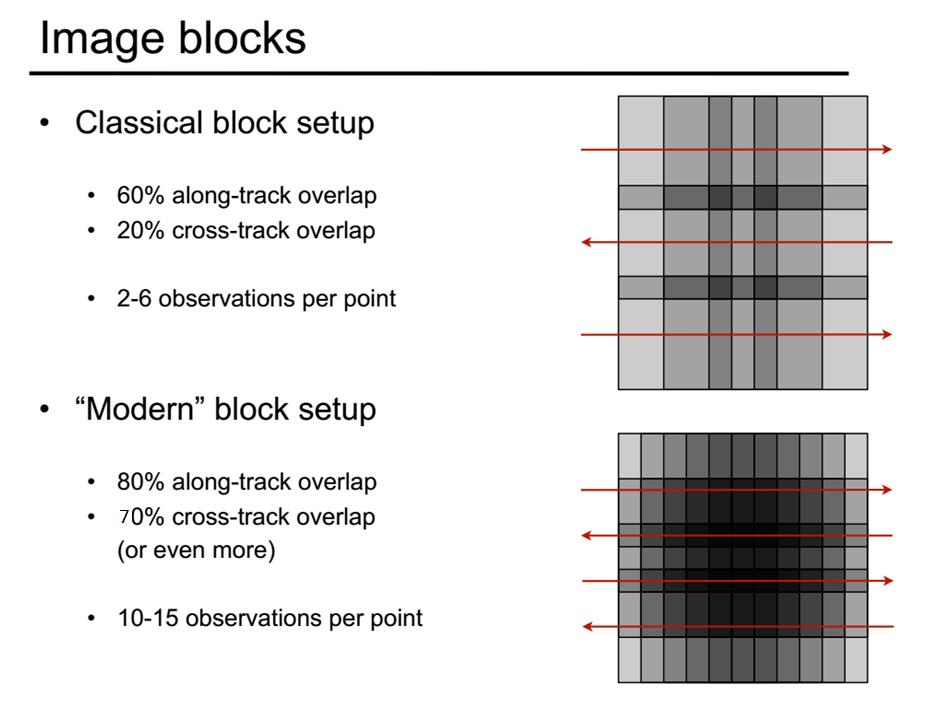
79 Case 1 : General Case near vertical photos; 1 regular grid Geo-location Accuracy No of images: 219 Processing Time: ~4.5h (upto dense cloud) 79
 3D model (point cloud) accurately represents features which are represented in orthoimage.")
80 Case 1 : General Case near vertical photos; 1 regular grid Overview of Result High geolocation accuracy: 2.4cm horizontal 11cm vertical Geometrical errors in sides of features (eg: building facades) 3D model (point cloud) accurately represents features which are represented in orthoimage. Some important points underneath, are not being reconstructed. Textured 3D model: 80
 are deformed in the 3D model.")
81 Case 1 : General Case near vertical photos; 1 regular grid Buildings covered by tree canopy (which are not visible in Orthoimage) are deformed in the 3D model. Geometry can not be extracted accurately 81
 A double grid is used with high overlap (80%) as 1 st grid covering the area by near vertical photos and 2 nd")
82 Case 2: Double Grid near vertical photos 1 regular grid + ~45 deg oblique perpendicular grid For detailed 3D reconstruction of an urban or semi urban area; flight plan should be designed to acquire most of details such as building facades in every direction (north, east, south, west) A double grid is used with high overlap (80%) as 1 st grid covering the area by near vertical photos and 2 nd grid by oblique images perpendicular to the first grid Vertical photos: High geometric accuracy; low details Slant images: low geometric accuracy; high details 1 near vertical images 2 ~45 deg oblique images 82

83 Case 2: Double Grid near vertical photos 1 regular grid + ~45 deg oblique perpendicular grid Geo-location Accuracy No of Images : 341 Near Vertical : 129 Oblique : 212 Processing time : ~ 12h 83
84 Case 2: Double Grid near vertical photos 1 regular grid + ~45 deg oblique perpendicular grid Overview of Result High location accuracy: 3.5 cm horizontal 3 cm vertical 3D point cloud represents the features (building / trees) with less distortions and greater amount of details 3D model can be used to identify important feature which are not visible in the orthoimage or general 3D model Increased computational complexity and increased time for processing. Textured 3D model: 84


85 Case 2: Double Grid This building is almost fully covered by tree canopy which makes unable to accurately detect its size and shape by top view ortho images. But in the textured 3d model the building is easily visible. Orthoimage Textured 3D model 85

86 Comparision case 1 vs case 2 Case 1 Case 2 86

87 Comparison case 1 vs case 2 Eg: The road in front of the energy building is highly covered by tree canopy. It is not possible to mark any point underneath just by orthoimage. 87


88 Comparison case 1 vs case 2 Case 1 Case 2 88

89 Case 3: Quad Grid near vertical photos 2 perpendicular grids + ~45deg oblique photos 2 perpendicular grid Maximum amount of details and accuracy for given flying height can be obtained using this configuration Trade off between details/accuracy vs processing time Very intensive processing; require more time and higher processing power Processing Time : h 1,2 near vertical photos 3,4 - ~45deg oblique images 89

90 Case 3: Quad Grid near vertical photos 2 perpendicular grids + ~45 deg oblique 2 perpendicular grids Geo-location Accuracy No of Images : 649 Near Vertical : 271 Oblique : 378 Processing time : ~ 170h 90

91 Photographic End & Side lap 80% Fw Overlap and 70% Side Overlap of Phantom 3 AGL 91
92 Remark Flat terrain with agricultural fields: In cases where the terrain is flat with homogeneous content, such as agriculture fields, it is difficult to extract common characteristic points (key-points) between the images. In order to achieve good results, it is recommended to use a Single or Double grid applying the following settings: At least 85% frontal overlap and at least 70% side overlap. Increase the flight height. In most cases, flying higher improves the results. 92
93 Remark Forest and dense vegetation: Trees and dense vegetation often have a different appearance between overlapping images due thousands of branches and leaves. Therefore, it is difficult to extract common characteristic points (key points) between the images. In order to achieve good results, it is recommended to use a Single or Double grid mission applying the following settings: At least 85% frontal overlap and at least 70% side overlap. Increase the flight height. At higher altitude, there is less perspective distortion, therefore causing less appearance problems. ) In other words, it is easier to detect visual similarities between overlapping images. The flight height in combination with the image pixel resolution and the focal length determine the Ground Sampling Distance (spatial resolution) of the images. Best results are obtained with a GSD higher than 10cm/pixel. 93
94 How flight plan is calculated Ground Sampling Distance (GSD): The Ground Sampling Distance (GSD) is the distance between the center of two consecutive pixels on the ground. It influences the accuracy and the quality of the final results as well as the details that are visible in the final Orthomosaic. The flight height [H] that is needed to obtain a given GSD can be computed and depends on the camera focal length [Fr], the camera sensor width [Sw], and the image width [Dw]. H / F R = D W / S W H = (DW * FR) / SW (1) Sw = real sensor width [mm] FR = real focal length [mm] H = flight height [m] Dw = distance covered on the ground by one image in the width direction (footprint width) [m]
95 How flight plan is calculated Ground Sampling Distance (GSD): Flying height (H): H / F R = D W / S W H = (DW * FR) / SW (1) Distance covered on the ground (Dw): D W = (imw * GSD) / 100 (2) Combining (1) and (2) H [m] = (imw * GSD * FR) / (SW * 100) (3) Note: The result is given in [m], considering that the GSD is in [cm/pixel]. Sw FR H Dw imw GSD = real sensor width [mm] = real focal length [mm] = flight height [m] = distance covered on the ground by an image in width direction (footprint width) [m] = image width [pixel] = desired GSD [cm/pixel]
96 How flight plan is calculated Ground Sampling Distance (GSD): Computation of the flight height to get a GSD of 5 [cm/pixel]: using a camera with a real focal length of 5 [mm] and a real sensor width of 6.17 [mm]. Assuming that the image width is 4000 [pixels] and using the equation (4), the flight height should be 162 [m]. H = (imw * GSD* FR ) / (Sw * 100) = (4000 * 5 * 5) / (6.17 * 100) = [m] Sw FR H Dw imw GSD = real sensor width [mm] = real focal length [mm] = flight height [m] = distance covered on the ground by an image in width direction (footprint width) [m] = image width [pixel] = desired GSD [cm/pixel]
97 How flight plan is calculated Image Rate for a given Frontal Overlap: The image shooting rate to achieve a given frontal overlap depends on the speed of the UAV/plane, the GSD and the pixel resolution of the camera. The higher the overlap, the easier it is for the software to find common points. Od = overlap * D (1) X = D - od (2) t = x / v (3) D = Dh = (imh * GSD) / 100 (4) od = overlap between two images in the flight direction [m] overlap = desired frontal overlap between two images [%] D = ground distance covered by one image in the flight direction [m] X = distance between two camera positions in the flight direction [m] v = flight speed [m/s] t = elapsed time between two images (image rate) [s] Dh = ground distance covered by one image in the height direction (footprint height) [m] imh = image height (in the flight direction) [pixel] GSD = desired GSD [cm/pixel]
98 How flight plan is calculated Image Rate for a given Frontal Overlap: Od = overlap * D (1) x = D - od (2) D = Dh = (imh * GSD) / 100 (4) Substituting (1) and (4) into Equation (2): x = Dh - overlap * Dh x = Dh * (1 - overlap) x = ((imh* GSD) / 100) * (1 - overlap) (5) Note: x is given in [m], considering that the GSD is in [cm/pixel]. od = overlap between two images in the flight direction [m] overlap = desired frontal overlap between two images [%] D = ground distance covered by one image in the flight direction [m] x = distance between two camera positions in the flight direction [m] v = flight speed [m/s] t = elapsed time between two images (image rate) [s] Dh = ground distance covered by one image in the height direction (footprint height) [m] imh = image height (in the flight direction) [pixel] GSD = desired GSD [cm/pixel]
99 How flight plan is calculated Image Rate for a given Frontal Overlap: In order to achieve an overlap of 75% (overlap = 0.75) and a GSD of 5 [cm/pixel]: supposing that the image height is 4000 [pixels]. speed of the UAV/plane is 30 [km/h] = 8.33 [m/s]. The image rate (t) should be 6 seconds: t = ((imh * GSD) / 100) * (1 - overlap) / v = ((4000 * 5 ) / 100) * (1-0.75) / 8.33 = 6 [s] od = overlap between two images in the flight direction [m] overlap = desired frontal overlap between two images [%] D = ground distance covered by one image in the flight direction [m] x = distance between two camera positions in the flight direction [m] v = flight speed [m/s] t = elapsed time between two images (image rate) [s] Dh = ground distance covered by one image in the height direction (footprint height) [m] imh = image height [pixel] GSD = desired GSD [cm/pixel]
100 100
101 UAV Flight Planning As drones combines with GNSS and IMU devices; UAV Flight can be automated Todays flight planning software attempts to do as much of the computation heavy lifting as possible so you can worry about the on-site issues and not worry about the tech. Combine Features As Automatic Flight Path Generation and Execution via waypoints Terrain Awareness: Ensure Safe Flight and Constant Overlap Base maps Auto Take-off / Auto Land 101


102 UAV Flight Planning - Features Automatic Flight Path Generation Terrain Awareness 102

 or aerial images can be used for")
103 UAV Flight Planning Factors To Be Considered UAVs are flying Low; Beware of Obstacles Very Limited Flight Time Understand the project goals clearly; Plan the mission accordingly Flying Height Image Overlap Camera Selection Flight Grid Placement Clear idea of the area to be surveyed Existing satellite images (Google earth) or aerial images can be used for reconnaissance 103


104 Flight Planning Software for DJI Drones Map Pilot for DJI: Pix4D Capture: DJI Ground Station Pro: DroneDeploy: So far the BEST ( Only available for ipad ) 104


105 Birds Attack!!! Beware 105
106 References Elements of Photogrammetry with Application in GIS, Fourth Edition Book by Bon DeWitt and Paul R. Wolf Cyrill Stachnisss Lecture Notes & videos on Photogrammetry 106

107 End 107
Volume 1 - Module 6 Geometry of Aerial Photography. I. Classification of Photographs. Vertical
 RSCC Volume 1 Introduction to Photo Interpretation and Photogrammetry Table of Contents Module 1 Module 2 Module 3.1 Module 3.2 Module 4 Module 5 Module 6 Module 7 Module 8 Labs Volume 1 - Module 6 Geometry
Acquisition of Aerial Photographs and/or Satellite Imagery
 Acquisition of Aerial Photographs and/or Satellite Imagery Acquisition of Aerial Photographs and/or Imagery From time to time there is considerable interest in the purchase of special-purpose photography
Sample Copy. Not For Distribution.
 Photogrammetry, GIS & Remote Sensing Quick Reference Book i EDUCREATION PUBLISHING Shubham Vihar, Mangla, Bilaspur, Chhattisgarh - 495001 Website: www.educreation.in Copyright, 2017, S.S. Manugula, V.
RPAS Photogrammetric Mapping Workflow and Accuracy
 RPAS Photogrammetric Mapping Workflow and Accuracy Dr Yincai Zhou & Dr Craig Roberts Surveying and Geospatial Engineering School of Civil and Environmental Engineering, UNSW Background RPAS category and
Phase One 190MP Aerial System
 White Paper Phase One 190MP Aerial System Introduction Phase One Industrial s 100MP medium format aerial camera systems have earned a worldwide reputation for its high performance. They are commonly used
Acquisition of Aerial Photographs and/or Imagery
 Acquisition of Aerial Photographs and/or Imagery Acquisition of Aerial Photographs and/or Imagery From time to time there is considerable interest in the purchase of special-purpose photography contracted
Chapters 1 & 2. Definitions and applications Conceptual basis of photogrammetric processing
 Chapters 1 & 2 Chapter 1: Photogrammetry Definitions and applications Conceptual basis of photogrammetric processing Transition from two-dimensional imagery to three-dimensional information Automation
Overview. Objectives. The ultimate goal is to compare the performance that different equipment offers us in a photogrammetric flight.
 Overview At present, one of the most commonly used technique for topographic surveys is aerial photogrammetry. This technique uses aerial images to determine the geometric properties of objects and spatial
Geometry of Aerial Photographs
 Geometry of Aerial Photographs Aerial Cameras Aerial cameras must be (details in lectures): Geometrically stable Have fast and efficient shutters Have high geometric and optical quality lenses They can
not to be republished NCERT Introduction To Aerial Photographs Chapter 6
 Chapter 6 Introduction To Aerial Photographs Figure 6.1 Terrestrial photograph of Mussorrie town of similar features, then we have to place ourselves somewhere in the air. When we do so and look down,
11/25/2009 CHAPTER THREE INTRODUCTION INTRODUCTION (CONT D) THE AERIAL CAMERA: LENS PHOTOGRAPHIC SENSORS
 THE AERIAL CAMERA: LENS PHOTOGRAPHIC SENSORS") INTRODUCTION CHAPTER THREE IC SENSORS Photography means to write with light Today s meaning is often expanded to include radiation just outside the visible spectrum, i. e. ultraviolet and near infrared
INTRODUCTION CHAPTER THREE IC SENSORS Photography means to write with light Today s meaning is often expanded to include radiation just outside the visible spectrum, i. e. ultraviolet and near infrared
Validation of the QuestUAV PPK System
 Validation of the QuestUAV PPK System 3cm in xy, 400ft, no GCPs, 100Ha, 25 flights Nigel King 1, Kerstin Traut 2, Cameron Weeks 3 & Ruairi Hardman 4 1 Director QuestUAV, 2 Data Analyst QuestUAV, 3 Production
EnsoMOSAIC Aerial mapping tools
 EnsoMOSAIC Aerial mapping tools Jakarta and Kuala Lumpur, 2013 Contents MosaicMill MM Application examples Software introduction System introduction Rikola HS sensor UAV platform examples SW Syst HS UAV
Aerial efficiency, photogrammetric accuracy
 Aerial efficiency, photogrammetric accuracy Why sensefly 3 reasons to choose the ebee Plus Large coverage for optimal efficiency The ebee Plus can map more square kilometres per flight, than any drone
CSI: Rombalds Moor Photogrammetry Photography
 Photogrammetry Photography Photogrammetry Training 26 th March 10:00 Welcome Presentation image capture Practice 12:30 13:15 Lunch More practice 16:00 (ish) Finish or earlier What is photogrammetry 'photo'
Aerial photography: Principles. Frame capture sensors: Analog film and digital cameras
 Aerial photography: Principles Frame capture sensors: Analog film and digital cameras Overview Introduction Frame vs scanning sensors Cameras (film and digital) Photogrammetry Orthophotos Air photos are
White Paper Reaching 1 cm (0.4 in) drone survey accuracy
 drone survey accuracy") White Paper Reaching 1 cm (0.4 in) drone survey accuracy 3x higher absolute accuracy with WingtraOne Latest tests in USA and Switzerland prove that the VTOL WingtraOne drone repeatably reaches the best-in-class
White Paper Reaching 1 cm (0.4 in) drone survey accuracy 3x higher absolute accuracy with WingtraOne Latest tests in USA and Switzerland prove that the VTOL WingtraOne drone repeatably reaches the best-in-class
Phase One ixu-rs1000 Accuracy Assessment Report Yu. Raizman, PhaseOne.Industrial, Israel
 17 th International Scientific and Technical Conference FROM IMAGERY TO DIGITAL REALITY: ERS & Photogrammetry Phase One ixu-rs1000 Accuracy Assessment Report Yu. Raizman, PhaseOne.Industrial, Israel 1.
sensefly Camera Collection
 Camera Collection A professional sensor for every application Introducing S.O.D.A. 3D 3D mapping, redefined Image: S.O.D.A. 3D oblique image (left) merging into 3D mesh (right). Stunning digital 3D reconstructions
Monitoring the vegetation success of a rehabilitated mine site using multispectral UAV imagery. Tim Whiteside & Renée Bartolo, eriss
 Monitoring the vegetation success of a rehabilitated mine site using multispectral UAV imagery Tim Whiteside & Renée Bartolo, eriss About the Supervising Scientist Main roles Working to protect the environment
Photogrammetry. Lecture 4 September 7, 2005
 Photogrammetry Lecture 4 September 7, 2005 What is Photogrammetry Photogrammetry is the art and science of making accurate measurements by means of aerial photography: Analog photogrammetry (using films:
Unmanned Aerial Vehicle Data Acquisition for Damage Assessment in. Hurricane Events
 Unmanned Aerial Vehicle Data Acquisition for Damage Assessment in Hurricane Events Stuart M. Adams a Carol J. Friedland b and Marc L. Levitan c ABSTRACT This paper examines techniques for data collection
PHOTOGRAMMETRY STEREOSCOPY FLIGHT PLANNING PHOTOGRAMMETRIC DEFINITIONS GROUND CONTROL INTRODUCTION
 PHOTOGRAMMETRY STEREOSCOPY FLIGHT PLANNING PHOTOGRAMMETRIC DEFINITIONS GROUND CONTROL INTRODUCTION Before aerial photography and photogrammetry became a reliable mapping tool, planimetric and topographic
White Paper Reaching 1 cm (0.4 in) drone survey accuracy
 drone survey accuracy") White Paper Reaching 1 cm (0.4 in) drone survey accuracy 3x higher absolute accuracy with WingtraOne Latest tests in the USA and Switzerland prove that the VTOL WingtraOne drone repeatedly reaches the
White Paper Reaching 1 cm (0.4 in) drone survey accuracy 3x higher absolute accuracy with WingtraOne Latest tests in the USA and Switzerland prove that the VTOL WingtraOne drone repeatedly reaches the
UAV PHOTOGRAMMETRY COMPARED TO TRADITIONAL RTK GPS SURVEYING
 UAV PHOTOGRAMMETRY COMPARED TO TRADITIONAL RTK GPS SURVEYING Brad C. Mathison and Amber Warlick March 20, 2016 Fearless Eye Inc. Kansas City, Missouri www.fearlesseye.com KEY WORDS: UAV, UAS, Accuracy
MINNESOTA DEPARTMENT OF TRANSPORTATION OFFICE OF LAND MANAGEMENT SURVEYING AND MAPPING SECTION PHOTOGRAMMETRY UNIT
 SEP. 2011 MINNESOTA DEPARTMENT OF TRANSPORTATION OFFICE OF LAND MANAGEMENT SURVEYING AND MAPPING SECTION PHOTOGRAMMETRY UNIT SPECIAL PROVISIONS FOR: GROUP 1: AERIAL PHOTOGRAPHY/PHOTOGRAMMETRIC LAB SERVICES
MSB Imagery Program FAQ v1
 MSB Imagery Program FAQ v1 (F)requently (A)sked (Q)uestions 9/22/2016 This document is intended to answer commonly asked questions related to the MSB Recurring Aerial Imagery Program. Table of Contents
Leica - 3 rd Generation Airborne Digital Sensors Features / Benefits for Remote Sensing & Environmental Applications
 Leica - 3 rd Generation Airborne Digital Sensors Features / Benefits for Remote Sensing & Environmental Applications Arthur Rohrbach, Sensor Sales Dir Europe, Middle-East and Africa (EMEA) Luzern, Switzerland,
UAS Photogrammetry Best Practices
 UAS Photogrammetry Best Practices Pennsylvania Society of Land Surveyors January 15, 2019 Bryan Baker Certified Mapping Scientist (UAS) Bryan Baker UAS Sales Manager Leica Geosystems Reality Capture Team
Lesson 4: Photogrammetry
 This work by the National Information Security and Geospatial Technologies Consortium (NISGTC), and except where otherwise Development was funded by the Department of Labor (DOL) Trade Adjustment Assistance
Principles of Photogrammetry
 Winter 2014 1 Instructor: Contact Information. Office: Room # ENE 229C. Tel: (403) 220-7105. E-mail: ahabib@ucalgary.ca Lectures (SB 148): Monday, Wednesday& Friday (10:00 a.m. 10:50 a.m.). Office Hours:
2019 NYSAPLS Conf> Fundamentals of Photogrammetry for Land Surveyors
 2019 NYSAPLS Conf> Fundamentals of Photogrammetry for Land Surveyors George Southard GSKS Associates LLC Introduction George Southard: Master s Degree in Photogrammetry and Cartography 40 years working
Deliverable 5-B: Review and Update on AURA System Requirements, Sensors, and Platforms Supplemental Report
 Deliverable 5-B: Review and Update on AURA System Requirements, Sensors, and Platforms Supplemental Report Focusing on education, research, and development of technology to sense and understand natural
CEE 6100 / CSS 6600 Remote Sensing Fundamentals 1 Topic 4: Photogrammetry
 CEE 6100 / CSS 6600 Remote Sensing Fundamentals 1 PHOTOGRAMMETRY DEFINITION (adapted from Manual of Photographic Interpretation, 2 nd edition, Warren Philipson, 1997) Photogrammetry and Remote Sensing:
VERIFICATION OF POTENCY OF AERIAL DIGITAL OBLIQUE CAMERAS FOR AERIAL PHOTOGRAMMETRY IN JAPAN
 VERIFICATION OF POTENCY OF AERIAL DIGITAL OBLIQUE CAMERAS FOR AERIAL PHOTOGRAMMETRY IN JAPAN Ryuji. Nakada a, *, Masanori. Takigawa a, Tomowo. Ohga a, Noritsuna. Fujii a a Asia Air Survey Co. Ltd., Kawasaki
LENSES. INEL 6088 Computer Vision
 LENSES INEL 6088 Computer Vision Digital camera A digital camera replaces film with a sensor array Each cell in the array is a Charge Coupled Device light-sensitive diode that converts photons to electrons
IMAGE ACQUISITION GUIDELINES FOR SFM
 IMAGE ACQUISITION GUIDELINES FOR SFM a.k.a. Close-range photogrammetry (as opposed to aerial/satellite photogrammetry) Basic SfM requirements (The Golden Rule): minimum of 60% overlap between the adjacent
Basics of Photogrammetry Note#6
 Basics of Photogrammetry Note#6 Photogrammetry Art and science of making accurate measurements by means of aerial photography Analog: visual and manual analysis of aerial photographs in hard-copy format
Cameras. CSE 455, Winter 2010 January 25, 2010
 Cameras CSE 455, Winter 2010 January 25, 2010 Announcements New Lecturer! Neel Joshi, Ph.D. Post-Doctoral Researcher Microsoft Research neel@cs Project 1b (seam carving) was due on Friday the 22 nd Project
6.098 Digital and Computational Photography Advanced Computational Photography. Bill Freeman Frédo Durand MIT - EECS
 6.098 Digital and Computational Photography 6.882 Advanced Computational Photography Bill Freeman Frédo Durand MIT - EECS Administrivia PSet 1 is out Due Thursday February 23 Digital SLR initiation? During
UltraCam and UltraMap Towards All in One Solution by Photogrammetry
 Photogrammetric Week '11 Dieter Fritsch (Ed.) Wichmann/VDE Verlag, Belin & Offenbach, 2011 Wiechert, Gruber 33 UltraCam and UltraMap Towards All in One Solution by Photogrammetry ALEXANDER WIECHERT, MICHAEL
Chapters 1-3. Chapter 1: Introduction and applications of photogrammetry Chapter 2: Electro-magnetic radiation. Chapter 3: Basic optics
 Chapters 1-3 Chapter 1: Introduction and applications of photogrammetry Chapter 2: Electro-magnetic radiation Radiation sources Classification of remote sensing systems (passive & active) Electromagnetic
MEDIUM FORMAT CAMERA EVALUATION BASED ON THE LATEST PHASE ONE TECHNOLOGY
 MEDIUM FORMAT CAMERA EVALUATION BASED ON THE LATEST PHASE ONE TECHNOLOGY T.Tölg a, G. Kemper b, D. Kalinski c a Phase One / Germany tto@phaseone.com b GGS GmbH, Speyer / Germany kemper@ggs-speyer.de c
IMAGE FORMATION. Light source properties. Sensor characteristics Surface. Surface reflectance properties. Optics
 IMAGE FORMATION Light source properties Sensor characteristics Surface Exposure shape Optics Surface reflectance properties ANALOG IMAGES An image can be understood as a 2D light intensity function f(x,y)
GEO 428: DEMs from GPS, Imagery, & Lidar Tuesday, September 11
 GEO 428: DEMs from GPS, Imagery, & Lidar Tuesday, September 11 Global Positioning Systems GPS is a technology that provides Location coordinates Elevation For any location with a decent view of the sky
LECTURE NOTES 2016 CONTENTS. Sensors and Platforms for Acquisition of Aerial and Satellite Image Data
 LECTURE NOTES 2016 Prof. John TRINDER School of Civil and Environmental Engineering Telephone: (02) 9 385 5020 Fax: (02) 9 313 7493 j.trinder@unsw.edu.au CONTENTS Chapter 1 Chapter 2 Sensors and Platforms
Structure from Motion (SfM) Photogrammetry Field Methods Manual for Students
 Photogrammetry Field Methods Manual for Students") Structure from Motion (SfM) Photogrammetry Field Methods Manual for Students Written by Katherine Shervais (UNAVCO) Introduction to SfM for Field Education The purpose of the Analyzing High Resolution
Structure from Motion (SfM) Photogrammetry Field Methods Manual for Students Written by Katherine Shervais (UNAVCO) Introduction to SfM for Field Education The purpose of the Analyzing High Resolution
ACCURACY ASSESSMENT OF DIRECT GEOREFERENCING FOR PHOTOGRAMMETRIC APPLICATIONS ON SMALL UNMANNED AERIAL PLATFORMS
 ACCURACY ASSESSMENT OF DIRECT GEOREFERENCING FOR PHOTOGRAMMETRIC APPLICATIONS ON SMALL UNMANNED AERIAL PLATFORMS O. Mian a, J. Lutes a, G. Lipa a, J. J. Hutton a, E. Gavelle b S. Borghini c * a Applanix
Image Fusion. Pan Sharpening. Pan Sharpening. Pan Sharpening: ENVI. Multi-spectral and PAN. Magsud Mehdiyev Geoinfomatics Center, AIT
 1 Image Fusion Sensor Merging Magsud Mehdiyev Geoinfomatics Center, AIT Image Fusion is a combination of two or more different images to form a new image by using certain algorithms. ( Pohl et al 1998)
Film Cameras Digital SLR Cameras Point and Shoot Bridge Compact Mirror less
 Film Cameras Digital SLR Cameras Point and Shoot Bridge Compact Mirror less Portraits Landscapes Macro Sports Wildlife Architecture Fashion Live Music Travel Street Weddings Kids Food CAMERA SENSOR
PROPERTY OF THE LARGE FORMAT DIGITAL AERIAL CAMERA DMC II
 PROPERTY OF THE LARGE FORMAT DIGITAL AERIAL CAMERA II K. Jacobsen a, K. Neumann b a Institute of Photogrammetry and GeoInformation, Leibniz University Hannover, Germany jacobsen@ipi.uni-hannover.de b Z/I
Experimental aerial photogrammetry with professional non metric camera Canon EOS 5D
 Experimental aerial photogrammetry with professional non metric camera Canon EOS 5D Ante Sladojević, Goran Mrvoš Galileo Geo Sustavi, Croatia 1. Introduction With this project we wanted to test professional
Lenses, exposure, and (de)focus
focus") Lenses, exposure, and (de)focus http://graphics.cs.cmu.edu/courses/15-463 15-463, 15-663, 15-862 Computational Photography Fall 2017, Lecture 15 Course announcements Homework 4 is out. - Due October 26
Lenses, exposure, and (de)focus http://graphics.cs.cmu.edu/courses/15-463 15-463, 15-663, 15-862 Computational Photography Fall 2017, Lecture 15 Course announcements Homework 4 is out. - Due October 26
VisionMap A3 Edge A Single Camera for Multiple Solutions
 Photogrammetric Week '15 Dieter Fritsch (Ed.) Wichmann/VDE Verlag, Belin & Offenbach, 2015 Raizman, Gozes 57 VisionMap A3 Edge A Single Camera for Multiple Solutions Yuri Raizman, Adi Gozes, Tel-Aviv ABSTRACT
AERIAL SURVEY TEST PROJECT WITH DJI PHANTOM 3 QUADROCOPTER DRONE
 T. Jancso, P. Engler, P. Udvardy Aerial Survey Test Project with DJI Phantom 3 Quadrocopter Drone AERIAL SURVEY TEST PROJECT WITH DJI PHANTOM 3 QUADROCOPTER DRONE Tamas JANCSO, Associate Professor Phd
Chapters 1-3. Chapter 1: Introduction and applications of photogrammetry Chapter 2: Electro-magnetic radiation. Chapter 3: Basic optics
 Chapters 1-3 Chapter 1: Introduction and applications of photogrammetry Chapter 2: Electro-magnetic radiation Radiation sources Classification of remote sensing systems (passive & active) Electromagnetic
HIGH RESOLUTION COLOR IMAGERY FOR ORTHOMAPS AND REMOTE SENSING. Author: Peter Fricker Director Product Management Image Sensors
 HIGH RESOLUTION COLOR IMAGERY FOR ORTHOMAPS AND REMOTE SENSING Author: Peter Fricker Director Product Management Image Sensors Co-Author: Tauno Saks Product Manager Airborne Data Acquisition Leica Geosystems
Baldwin and Mobile Counties, AL Orthoimagery Project Report. Submitted: March 23, 2016
 2015 Orthoimagery Project Report Submitted: Prepared by: Quantum Spatial, Inc 523 Wellington Way, Suite 375 Lexington, KY 40503 859-277-8700 Page i of iii Contents Project Report 1. Summary / Scope...
Application of GIS to Fast Track Planning and Monitoring of Development Agenda
 Application of GIS to Fast Track Planning and Monitoring of Development Agenda Radiometric, Atmospheric & Geometric Preprocessing of Optical Remote Sensing 13 17 June 2018 Outline 1. Why pre-process remotely
ECEN 4606, UNDERGRADUATE OPTICS LAB
 ECEN 4606, UNDERGRADUATE OPTICS LAB Lab 2: Imaging 1 the Telescope Original Version: Prof. McLeod SUMMARY: In this lab you will become familiar with the use of one or more lenses to create images of distant
VisionMap Sensors and Processing Roadmap
 Vilan, Gozes 51 VisionMap Sensors and Processing Roadmap YARON VILAN, ADI GOZES, Tel-Aviv ABSTRACT The A3 is a family of digital aerial mapping cameras and photogrammetric processing systems, which is
Coastal Imaging of Morphology
 Coastal Imaging of Morphology Katherine Brodie 1, Margaret Palmsten 2, Jenna Long 3, and Brittany Bruder 1 1 U.S. Army Engineer Research and Development Center, Coastal and Hydraulics Laboratory, Duck,
Colorado School of Mines. Computer Vision. Professor William Hoff Dept of Electrical Engineering &Computer Science.
 Professor William Hoff Dept of Electrical Engineering &Computer Science http://inside.mines.edu/~whoff/ 1 Sensors and Image Formation Imaging sensors and models of image formation Coordinate systems Digital
RESEARCH ON LOW ALTITUDE IMAGE ACQUISITION SYSTEM
 RESEARCH ON LOW ALTITUDE IMAGE ACQUISITION SYSTEM 1, Hongxia Cui, Zongjian Lin, Jinsong Zhang 3,* 1 Department of Information Science and Engineering, University of Bohai, Jinzhou, Liaoning Province,11,
Background. Computer Vision & Digital Image Processing. Improved Bartlane transmitted image. Example Bartlane transmitted image
 Background Computer Vision & Digital Image Processing Introduction to Digital Image Processing Interest comes from two primary backgrounds Improvement of pictorial information for human perception How
Govt. Engineering College Jhalawar Model Question Paper Subject- Remote Sensing & GIS
 Govt. Engineering College Jhalawar Model Question Paper Subject- Remote Sensing & GIS Time: Max. Marks: Q1. What is remote Sensing? Explain the basic components of a Remote Sensing system. Q2. What is
ME 6406 MACHINE VISION. Georgia Institute of Technology
 ME 6406 MACHINE VISION Georgia Institute of Technology Class Information Instructor Professor Kok-Meng Lee MARC 474 Office hours: Tues/Thurs 1:00-2:00 pm kokmeng.lee@me.gatech.edu (404)-894-7402 Class
Princeton University COS429 Computer Vision Problem Set 1: Building a Camera
 Princeton University COS429 Computer Vision Problem Set 1: Building a Camera What to submit: You need to submit two files: one PDF file for the report that contains your name, Princeton NetID, all the
Chapter 1 Overview of imaging GIS
 Chapter 1 Overview of imaging GIS Imaging GIS, a term used in the medical imaging community (Wang 2012), is adopted here to describe a geographic information system (GIS) that displays, enhances, and facilitates
Assessing the Accuracy of Ortho-image using Photogrammetric Unmanned Aerial System
 Assessing the Accuracy of Ortho-image using Photogrammetric Unmanned Aerial System H. H. Jeong a, J. W. Park a, J. S. Kim a, C. U. Choi a, * a Dept. of Spatial Information Engineering, Pukyong National
Calibration Certificate
 Calibration Certificate Digital Mapping Camera (DMC) DMC Serial Number: DMC01-0053 CBU Serial Number: 0100053 For MPPG AERO Sp. z. o. o., ul. Kaczkowskiego 6 33-100 Tarnow Poland System Overview Flight
Photomod Lite Contest 2013 Creating vegetation map using UAV at Seaside Palouki forest (Greece) by Apostolos Nteris
 by Apostolos Nteris") P r o j e c t I n f o r m a t i o n Title: Creating vegetation map using UAV at seaside Palouki forest (Greece) Author: Apostolos Nteris, Surveyor engineer OLYZON consulting - Trikala Greece Contact: Apostolos
P r o j e c t I n f o r m a t i o n Title: Creating vegetation map using UAV at seaside Palouki forest (Greece) Author: Apostolos Nteris, Surveyor engineer OLYZON consulting - Trikala Greece Contact: Apostolos
CALIBRATING THE NEW ULTRACAM OSPREY OBLIQUE AERIAL SENSOR Michael Gruber, Wolfgang Walcher
 CALIBRATING THE NEW ULTRACAM OSPREY OBLIQUE AERIAL SENSOR Michael Gruber, Wolfgang Walcher Microsoft UltraCam Business Unit Anzengrubergasse 8/4, 8010 Graz / Austria {michgrub, wwalcher}@microsoft.com
Topographic mapping from space K. Jacobsen*, G. Büyüksalih**
 Topographic mapping from space K. Jacobsen*, G. Büyüksalih** * Institute of Photogrammetry and Geoinformation, Leibniz University Hannover ** BIMTAS, Altunizade-Istanbul, Turkey KEYWORDS: WorldView-1,
APPLICATIONS AND LESSONS LEARNED WITH AIRBORNE MULTISPECTRAL IMAGING
 APPLICATIONS AND LESSONS LEARNED WITH AIRBORNE MULTISPECTRAL IMAGING James M. Ellis and Hugh S. Dodd The MapFactory and HJW Walnut Creek and Oakland, California, U.S.A. ABSTRACT Airborne digital frame
CALIBRATION OF IMAGING SATELLITE SENSORS
 CALIBRATION OF IMAGING SATELLITE SENSORS Jacobsen, K. Institute of Photogrammetry and GeoInformation, University of Hannover jacobsen@ipi.uni-hannover.de KEY WORDS: imaging satellites, geometry, calibration
CHARACTERISTICS OF REMOTELY SENSED IMAGERY. Spatial Resolution
 CHARACTERISTICS OF REMOTELY SENSED IMAGERY Spatial Resolution There are a number of ways in which images can differ. One set of important differences relate to the various resolutions that images express.
UltraCam Eagle Prime Aerial Sensor Calibration and Validation
 UltraCam Eagle Prime Aerial Sensor Calibration and Validation Michael Gruber, Marc Muick Vexcel Imaging GmbH Anzengrubergasse 8/4, 8010 Graz / Austria {michael.gruber, marc.muick}@vexcel-imaging.com Key
Computer Vision. The Pinhole Camera Model
 Computer Vision The Pinhole Camera Model Filippo Bergamasco (filippo.bergamasco@unive.it) http://www.dais.unive.it/~bergamasco DAIS, Ca Foscari University of Venice Academic year 2017/2018 Imaging device
Leica ADS80 - Digital Airborne Imaging Solution NAIP, Salt Lake City 4 December 2008
 Luzern, Switzerland, acquired at 5 cm GSD, 2008. Leica ADS80 - Digital Airborne Imaging Solution NAIP, Salt Lake City 4 December 2008 Shawn Slade, Doug Flint and Ruedi Wagner Leica Geosystems AG, Airborne
Overview. Pinhole camera model Projective geometry Vanishing points and lines Projection matrix Cameras with Lenses Color Digital image
 Camera & Color Overview Pinhole camera model Projective geometry Vanishing points and lines Projection matrix Cameras with Lenses Color Digital image Book: Hartley 6.1, Szeliski 2.1.5, 2.2, 2.3 The trip
Get the Shot! Photography + Instagram Workshop September 21, 2013 BlogPodium. Saturday, 21 September, 13
 Get the Shot! Photography + Instagram Workshop September 21, 2013 BlogPodium Part One: Taking your camera off manual Technical details Common problems and how to fix them Practice Ways to make your photos
Jens Kremer ISPRS Hannover Workshop 2017,
 Jens Kremer ISPRS Hannover Workshop 2017, 8.06.2017 Modular aerial camera-systems The IGI UrbanMapper 2-in1 concept System Layout The DigiCAM-100 module The IGI UrbanMapper Sensor geometry & stitching
Photo Scale The photo scale and representative fraction may be calculated as follows: PS = f / H Variables: PS - Photo Scale, f - camera focal
 Scale Scale is the ratio of a distance on an aerial photograph to that same distance on the ground in the real world. It can be expressed in unit equivalents like 1 inch = 1,000 feet (or 12,000 inches)
PRELIMINARY RESULTS FROM THE PORTABLE IMAGERY QUALITY ASSESSMENT TEST FIELD (PIQuAT) OF UAV IMAGERY FOR IMAGERY RECONNAISSANCE PURPOSES
 OF UAV IMAGERY FOR IMAGERY RECONNAISSANCE PURPOSES") PRELIMINARY RESULTS FROM THE PORTABLE IMAGERY QUALITY ASSESSMENT TEST FIELD (PIQuAT) OF UAV IMAGERY FOR IMAGERY RECONNAISSANCE PURPOSES R. Dabrowski a, A. Orych a, A. Jenerowicz a, P. Walczykowski a, a
PRELIMINARY RESULTS FROM THE PORTABLE IMAGERY QUALITY ASSESSMENT TEST FIELD (PIQuAT) OF UAV IMAGERY FOR IMAGERY RECONNAISSANCE PURPOSES R. Dabrowski a, A. Orych a, A. Jenerowicz a, P. Walczykowski a, a
Following are the geometrical elements of the aerial photographs:
 Geometrical elements/characteristics of aerial photograph: An aerial photograph is a central or perspective projection, where the bundles of perspective rays meet at a point of origin called perspective
NREM 345 Week 2, Material covered this week contributes to the accomplishment of the following course goal:
 NREM 345 Week 2, 2010 Reading assignment: Chapter. 4 and Sec. 5.1 to 5.2.4 Material covered this week contributes to the accomplishment of the following course goal: Goal 1: Develop the understanding and
Assessment of Unmanned Aerial Vehicle for Management of Disaster Information
 Journal of the Korea Academia-Industrial cooperation Society Vol. 16, No. 1 pp. 697-702, 2015 http://dx.doi.org/10.5762/kais.2015.16.1.697 ISSN 1975-4701 / eissn 2288-4688 Assessment of Unmanned Aerial
ASPECTS OF DEM GENERATION FROM UAS IMAGERY
 ASPECTS OF DEM GENERATION FROM UAS IMAGERY A. Greiwea,, R. Gehrke a,, V. Spreckels b,, A. Schlienkamp b, Department Architecture, Civil Engineering and Geomatics, Fachhochschule Frankfurt am Main, Germany
Introduction to camera usage. The universal manual controls of most cameras
 Introduction to camera usage A camera in its barest form is simply a light tight container that utilizes a lens with iris, a shutter that has variable speeds, and contains a sensitive piece of media, either
SFR 406 Spring 2015 Lecture 7 Notes Film Types and Filters
 SFR 406 Spring 2015 Lecture 7 Notes Film Types and Filters 1. Film Resolution Introduction Resolution relates to the smallest size features that can be detected on the film. The resolving power is a related
Introduction to Photogeology
 Geological Mapping 1 Academic Year 2016/2017 Introduction to Photogeology Igor Vlahović igor.vlahovic@rgn.hr Today we will say a little about basic photogeological analysis of terrain: about aerial photographs,
Technical Evaluation of Khartoum State Mapping Project
 Technical Evaluation of Khartoum State Mapping Project Nagi Zomrawi 1 and Mohammed Fator 2 1 School of Surveying Engineering, Collage of Engineering, Sudan University of Science and Technology, Khartoum,
The Hyperspectral UAV (HyUAV) a novel UAV-based spectroscopy tool for environmental monitoring
 a novel UAV-based spectroscopy tool for environmental monitoring") The Hyperspectral UAV (HyUAV) a novel UAV-based spectroscopy tool for environmental monitoring R. Garzonio 1, S. Cogliati 1, B. Di Mauro 1, A. Zanin 2, B. Tattarletti 2, F. Zacchello 2, P. Marras 2 and
The Hyperspectral UAV (HyUAV) a novel UAV-based spectroscopy tool for environmental monitoring R. Garzonio 1, S. Cogliati 1, B. Di Mauro 1, A. Zanin 2, B. Tattarletti 2, F. Zacchello 2, P. Marras 2 and
RADIOMETRIC AND GEOMETRIC CHARACTERISTICS OF PLEIADES IMAGES
 RADIOMETRIC AND GEOMETRIC CHARACTERISTICS OF PLEIADES IMAGES K. Jacobsen a, H. Topan b, A.Cam b, M. Özendi b, M. Oruc b a Leibniz University Hannover, Institute of Photogrammetry and Geoinformation, Germany;
Cameras. Steve Rotenberg CSE168: Rendering Algorithms UCSD, Spring 2017
 Cameras Steve Rotenberg CSE168: Rendering Algorithms UCSD, Spring 2017 Camera Focus Camera Focus So far, we have been simulating pinhole cameras with perfect focus Often times, we want to simulate more
Processing of stereo scanner: from stereo plotter to pixel factory
 Photogrammetric Week '03 Dieter Fritsch (Ed.) Wichmann Verlag, Heidelberg, 2003 Bignone 141 Processing of stereo scanner: from stereo plotter to pixel factory FRANK BIGNONE, ISTAR, France ABSTRACT With
HD aerial video for coastal zone ecological mapping
 HD aerial video for coastal zone ecological mapping Albert K. Chong University of Otago, Dunedin, New Zealand Phone: +64 3 479-7587 Fax: +64 3 479-7586 Email: albert.chong@surveying.otago.ac.nz Presented
This document is a preview generated by EVS
 INTERNATIONAL STANDARD ISO 17850 First edition 2015-07-01 Photography Digital cameras Geometric distortion (GD) measurements Photographie Caméras numériques Mesurages de distorsion géométrique (DG) Reference