FV1000 FLUOVIEW. FLUOVIEW Always Evolving. Confocal Laser Scanning Biological Microscope.
|
|
|
- Derrick Goodwin
- 6 years ago
- Views:
Transcription

1 Confocal Laser Scanning Biological Microscope FV1000 FLUOVIEW FLUOVIEW Always Evolving FLUOVIEW website OLYMPUS CORPORATION is ISO14001 certified. OLYMPUS CORPORATION is FM553994/ISO9001 certified. Illumination devices for microscope have suggested lifetimes. Periodic inspections are required. Please visit our web site for details. This device is designed for use in industrial environments for the EMC performance (IEC Class A device). Using it in a residential environment may affect other equipment in the environment. Windows is a registered trademark of Microsoft Corporation in the United States and other countries. All other company and product names are registered trademarks and/or trademarks of their respective owners. Images on the display are simulated. Specifications and appearances are subject to change without any notice or obligation on the part of the manufacturer. Printed in Japan M1707E

2 FLUOVIEW From Imaging to Analysis Olympus is Opening up New Worlds FLUOVIEW More Advanced than Ever The Olympus FLUOVIEW FV1000 confocal laser scanning microscope delivers efficient and reliable performance together with the high resolution required for multi-dimensional observation of cell and tissue morphology, and precise molecular localization. The FV1000 incorporates the industry s first dedicated photostimulation scanner to achieve simultaneous targeted laser stimulation and imaging for real-time visualization of rapid cell responses. The FV1000 also measures diffusion coefficients of intracellular molecules, quantifying molecular kinetics. Quite simply, the FLUOVIEW FV1000 represents a new plateau, bringing imaging to analysis. Olympus continues to drive forward the development of FLUOVIEW microscopes, using input from researchers to meet their evolving demands and supplying robust solutions from imaging to analysis. From Imaging to Analysis FV1000 Quality Performance with Innovative Design FV10i Advanced Deeper Imaging with High Resolution FV1000MPE FV1000 is a class 3B laser product. FV10i is a class 1 laser product. FV1000MPE is a class 3B laser product. 1 2


3 Advanced FLUOVIEW Systems Enhance the Power of Your Research Superb Optical Systems Set the Standard for Accuracy and Sensitivity. Two types of detectors deliver enhanced accuracy and sensitivity, and are paired with a new objective with low chromatic aberration, to deliver even better precision for colocalization analysis. These optical advances boost the overall system capabilities and raise performance to a new level. Imaging, Stimulation and Measurement Advanced Analytical Methods for Quantification. Now equipped to measure the diffusion coefficients of intracellular molecules, for quantification of the dynamic interactions of molecules inside live cells. With robust stimulation capabilities for neuroscience, optogenetics, and calcium imaging, FLUOVIEW brings power to your research. Evolving Systems Meet the Demands of Your Application. Upgradeable system with optional hardware and software to meet the demands of your research. Your system can grow with your research needs, from routine imaging to the most advanced multiphoton applications. 3 4


 HeNe(G) laser (543 nm) Laser")


 objectives.")
4 Technology / Hardware Excellent Precision, Sensitivity and Stability. FLUOVIEW Enables Precise, Bright Imaging with Minimum Phototox icity. Main scanner SIM Scanner * Barrier filter PMT Microscope * Option Laser combiner Grating Grating PMT PMT LD635 LD559 AOTF Broadband fiber * Confocal pinhole Galvanometer scanning mirrors Specimen UIS2 objectives LD473 LD405 AOTF Broadband fiber Galvanometer scanning mirrors Pupil projection lens Laser combiner/fiber Scanners/Detection Optical System Samples and Specimens Diode Laser Greater stability, longer service life and lower operating cost are achieved using diode lasers. Laser Feedback Control Scanner unit is equipped with laser power monitor for feedback control enhancing stable laser output. Laser Compatibility Diode laser : 405 nm, 440 nm, 473 nm, 559 nm, 635 nm Gas laser : Multi-line Ar laser (458 nm, 488 nm, 515 nm) HeNe(G) laser (543 nm) Laser Combiner Two versions available. Single fiber-type combiner is used for main scanner FV1000 with up to six lasers, ranging from 405 to 635 nm. Dual fiber-type combiner is used for photostimulation with main and SIM scanner FV1000. High Sensitivity Detection System High-sensitivity and high S/N ratio optical performance is achieved through the integration of a pupil projection lens, use of a high sensitivity photomultiplier tube and an analog processing circuit with minimal noise. Enables high S/N ratio image acquisition with minimal laser power to reduce phototoxicity. Up to Four Simultaneous Confocal Channels Three integrated confocal PMT detectors, and optional module with fourth confocal PMT expandable up to four PMT channels. Motorized Microscopes Compatible with Olympus IX81 inverted microscope and upright microscopes including the BX61WI focusing nosepiece and fixed stage system, the preferred system for patch clamping and multiphoton imaging. UIS2 Objectives Olympus UIS2 objectives offer worldleading, infinity-corrected optics that deliver unsurpassed optical performance over a wide range of wavelengths. High S/N Ratio Objectives with Suppressed Autofluorescence Olympus offers a line of high numerical aperture objectives with improved fluorescence S/N ratio, including objectives with exceptional correction for chromatic aberration, oil-, water- and silicone immersion objectives, and total internal reflection fluorescence (TIRF) objectives. Supports a Wide Range of Samples and Specimens Tissue culture dishes, slide chambers, microplates and glass slides can be used with live cells and fixed specimens. Broadband Fiber Broadband fiber connection for nm lasers, to achieve an ideal point light source with minimal color shift and position shift between images. Spectral Scanning Unit Filter Scanning Unit IX81 Two Versions of Light Detection System Spectral detection for high-precision spectroscopy with 2 nm resolution. Filter detection equipped with high quality filter wheels. BX61 5 6


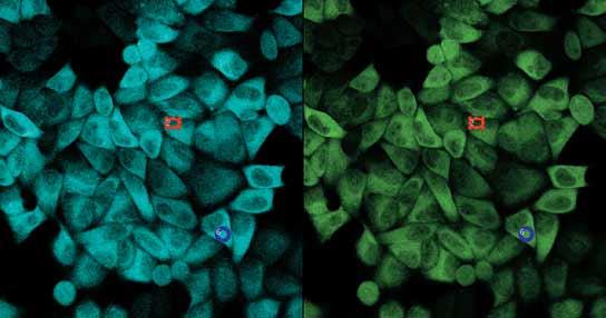
5 2,600 2,400 2,200 2,000 1,800 1,600 1,400 1,200 1, Wavelength Technology / Hardware Two Versions of Light Detection System that Set New Standards for Optical Performance. SIM Scanner Unit for Simultaneous Photostimulation and Imaging. Spectral Based Detection Flexibility and High Sensitivity Spectral detection using gratings for 2 nm wavelength resolution and image acquisition matched to fluorescence wavelength peaks. User adjustable bandwidth of emission spectrum for acquiring bright images with minimal crosstalk. SIM (Simultaneous) Scanner Unit Combines the main scanner with a dedicated photostimulation scanner for investigating the trafficking of fluorescent-labeled molecules and marking of specific live cells. Simultaneous Photostimulation and Imaging Performs simultaneous photostimulation and imaging to acquire images of immediate cell responses to stimulation in photobleaching experiments. Branching of laser in laser combiner. Lasers are used for both imaging and photostimulation. LD635 LD559 LD473 LD405 AOTF AOTF Precise Spectral Imaging The spectral detection unit uses a grating method that offers linear dispersion compared with prism nonlinear dispersion. The unit provides uniform 2 nm wavelength resolution across the entire detection spectrum and high-sensitivity photomultiplier tube detectors. Fluorescence separation can be achieved through unmixing, even when cross-talk is generated by multiple fluorescent dyes with similar peaks. A standard third filter channel is provided without a grating allowing researchers greater flexibility and sensitivity. Intensity EGFP EYFP Fluorescence Separation EYFP EGFP EGFP (dendrite) EYFP (synapse) XYλ Wavelength detection range: 495 nm 561 nm in 2 nm steps Excitation wavelength: 488 nm Courtesy of: Dr. Shigeo Okabe Department of Anatomy and Cell Biology, Tokyo Medical and Dental University Modifiable Stimulation Area During Imaging The stimulation area can be moved to a different position on the cell during imaging, providing a powerful tool for photoactivation and photoconversion experiments. Unique "Tornado" Scanning for Efficient Bleaching Conventional raster scanning does not always complete photobleaching quickly due to the necessity of reversing the scan direction for each line. Tornado scanning greatly improves bleaching efficiency by significantly reducing unnecessary scanning. *The Tornado scanning capability is excellent for Channelrhodopsin-2 activation. Tornado scanning ROI (region of interest) scanning Filter Based Detection Enhanced Sensitivity Three-channel scan unit with detection system featuring hard coated filter base. High-transmittance and high S/N ratio optical performance is achieved through integration of a pupil projection lens within the optics, the use of a high sensitivity photomultiplier and an analog processing circuit with minimal noise. Superfluous scanning areas. High-Performance Filters Deliver Outstanding Separation Special coatings deliver exceptionally sharp transitions to a degree never achieved before, for acquisition of brighter fluorescence images. ROI (region of interest) scanning. Tornado scanning. 100 DM488/543/633 Comparison Cell membrane stained with DIO, and subjected to both conventional ROI and tornado scanning. Transmittance (%) Wavelength (nm) Wide Choice of Bleaching Modes Various scan modes can be used for both the observation area and stimulation area. Enables free-form bleaching of designated points, lines, free-lines, rectangles and circles. Multi-Purpose Laser Combiner All lasers can be used for both Imaging and photostimulation. LD405/LD440/LD473/LD559/LD635/ Multi Argon (458 nm, 488 nm, 515 nm)/hene(g) (543 nm) Laser Sharing with Main Scanner Dual fiber laser combiner provides laser sharing between the SIM scanner and main scanner, eliminating the need to add a separate laser for stimulation. Conventional mirror unit High-performance mirror unit 7 8


 Compared for PSF fluorescent beads (405 nm, 633 nm).")
 0.5 0.0-0.5 400 450 Low Chromatic Aberration Objective PLAPON60xOSC Magnification: 60x NA: 1.")
 *Chromatic aberration values are design")


, the refractive index of silicone oil remains constant and there is no need to add more")


 W.D.: 0.8 mm Cover glass thickness: 0.13 0.")
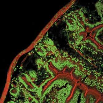
6 Technology / Hardware Exceptional Resolution for Colocalization Analysis and Imaging of Cytoplasmic Membrane. The World's First Silicone Immersion Objectives for Live Sample Imaging. Super Corrected Objective Silicone Immersion Objective Best Reliability for Colocalization Analysis A new high NA oil-immersion objective minimizes chromatic aberration in the nm region for enhanced imaging performance and image resolution at 405 nm. Delivers a high degree of correction for both lateral and axial chromatic aberration, for acquisition of 2D and 3D images with excellent and reliable accuracy, and improved colocalization analysis. The objective also compensates for chromatic aberration in the near infrared up to 850 nm. Performance Comparison of PLAPON 60xOSC and UPLSAPO 60xO Axial chromatic aberration (Z direction) Compared for PSF fluorescent beads (405 nm, 633 nm). Lateral chromatic aberration (X-Y direction) Compared for PSF fluorescent beads (405 nm, 488 nm, 633 nm). 3D image Tubulin in Ptk2 cells labeled with two colors (405 nm, 635 nm) and compared. PLAPON60xOSC Approx. 0 µm UPLSAPO60xO Approx. 0.5 µm Approx. 0.1 µm Approx. 0.2 µm Focal plane (µm) Low Chromatic Aberration Objective PLAPON60xOSC Magnification: 60x NA: 1.4 (oil immersion) W.D.: 0.12 mm Chromatic aberration compensation range: nm Optical data provided for each objective. Chromatic Aberration Comparison for PLAPON 60xOSC and UPLSAPO 60xO Lateral Chromatic Aberration UPLSAPO60xO PLAPON 60xOSC Wavelength (nm) *Chromatic aberration values are design values and are not guaranteed values. The Superior Choice for Observing Live Samples The refractive index of silicone oil (ne 1.40) matches very well to most live biological samples (ne 1.38). Using silicone oil as an immersion medium can minimize spherical aberration caused by refractive index mismatch resulting in brighter images with a greater signal to noise ratio. High-resolution Silicone Immersion Objectives Silicone immersion objectives can be designed with a larger numerical aperture (NA) than water immersion objectives, increasing image resolution and brightness. Silicone Oil is Ideal for Long-term, Time-lapse Observation The properties of silicone oil make it an excellent choice for long-term, stable time-lapse observation. It remains unchanged in 37ºC environments suited to the observation of live samples. Because drying and increase of viscosity are not a problem (unlike with water and glycerol immersion media), the refractive index of silicone oil remains constant and there is no need to add more fluid over time. Refractive Index is Important with Deep Tissue Observation In deep tissue observation, image quality depends on keeping the refractive index of the sample and immersion medium as close to each other as possible. Water immersion objective Sample ne 1.38 Silicone immersion objective UPLSAPO30xS: For Broader View and Greater Depth This low-magnification, high-na objective delivers highresolution imaging over a broad sample area. It enables continuous observation of high-resolution images from low to high magnification, using the zoom function of laser scanning microscopes. NEW Magnification: 30x NA: 1.05 (silicone oil immersion) W.D.: 0.8 mm Cover glass thickness: mm Operation temperature: 23ºC 37ºC UPLSAPO60xS: For 3D with Superior Resolution This high-magnification, high-na objective enables highly detailed imaging of live samples. It is ideally suited for high resolution 3D imaging. NEW Magnification: 60x NA: 1.30 (silicone oil immersion) W.D.: 0.3 mm Cover glass thickness: mm Operation temperature: 23ºC 37ºC TIRFM (Total Internal Reflection Fluorescence Microscope) System Switchable between Confocal and TIRFM Imaging Switchable between confocal and TIRFM imaging for localization of proteins on the cytoplasmic membrane surface and acquisition of sectioning images within cells. Software Control of TIRF Illumination Built-in laser provides TIRF illumination. Software can be used to tune the angle of incidence of excitation light and calculates the penetration depth of the evanescent wave based on the TIRF objective used. Water ne 1.33 When working with a water immersion objective, the difference between the refractive index of the samples and water results in spherical aberration in deep tissue, causing resolution to deteriorate and fluorescence to become dim. Cover glass ne 1.52 When working with a silicone immersion objective, the difference between the refractive index of the samples and silicone oil is minimal. So it achieves brighter fluorescence images with higher resolution for deep tissue. Silicone oil ne 1.40 Silicone Immersion Oil SIL300CS-30SC Refractive index: ne=1.406, 23ºC Net 30 ml Low autofluorescence High-Numerical Aperture Objectives for TIRF Illumination A line of high-numerical aperture (NA) objectives is available for TIRF illumination. TIRFM LSM GFP Pak K298A in HeLa cells. Courtesy of Dr.J M Dong of sgsk-nrp laboratory, Singapore APON60xOTIRF NA : 1.49 (oil immersion) W.D.: 0.1 mm UAPON100xOTIRF NA : 1.49 (oil immersion) W.D.: 0.1 mm UAPON150xOTIRF NA : 1.45 (oil immersion) W.D.: 0.08 mm Apo100xOHR NA : 1.65 (oil immersion) W.D.: 0.1 mm (Customized cover glass and immersion oil) XY: 466 µm x 224 µm (777 x 374 pixel) Confocal image of a Drosophila embryo at stage 11 expressing the tracheal maker trh-lacz (Cy3, red) and the cell membrane maker DIg (Alexa488, green). Enlarged view shows invaginating tracheal placode. Courtesy of Dr. Takefumi Kondo, Dr. Shigeo Hayashi Laboratory for Morphogenetic Signaling, RIKEN Center for Developmental Biology XY: 120 µm x 90 µm (800 x 600 pixel) Z: 21 µm (42 slices) 9 10


.")

.")


7 Technology / Hardware User-Friendly Software to Support Your Research. Optional Software with Broad Functionality. Diffusion Measurement Package For analysis of intracellular molecular interactions, signal transduction and other processes, by determining standard diffusion coefficients. Supports a wide range of diffusion analysis using point FCS, RICS and FRAP. Multi Stimulation Software Configure multiple stimulation points and conditions for photostimulation synchronized with imaging, for detailed analysis of the connectivity of cells within the stimulation area. Configurable Emission Wavelength Select the dye name to set the optimal filters and laser lines. Wide Choice of Scanning Modes Several available scanning modes including ROI, point and high-speed bidirectional scanning. Image Acquisition by Application User-friendly icons offer quick access to functions, for image acquisition according to the application (XYZ, XYT, XYZT, XYλ, XYλT). Re-Use Function Open previously configured scanning conditions and apply them to new or subsequent experiments. Multi-Area Time-Lapse Software Configurable Excitation Laser Power Easily adjust the optimum laser power for each specimen (live cells and fixed specimens). Time Controller Precisely synchronizes different experimental protocols including FRAP, FLIP and FRET by acceptor photobleaching and time-lapse. Save and open settings for later use. Help Guide Comprehensive help guide describes the functions and usage for each command, and overall sequence of operations. Multi-Area Time-Lapse Software control of the motorized XY stage enables multiple measurement points in glass slides, 35 mm dishes or individual microplate wells. Repeated imaging of multiple cells improves the statistical power of time-lapse experiments. Mosaic Imaging A motorized XY stage is programmed with the use of a high-magnification objective to acquire continuous images from adjacent fields of view, to assemble a single, high resolution image covering a wide area. Three-dimensional images can also be assembled using XYZ acquisition


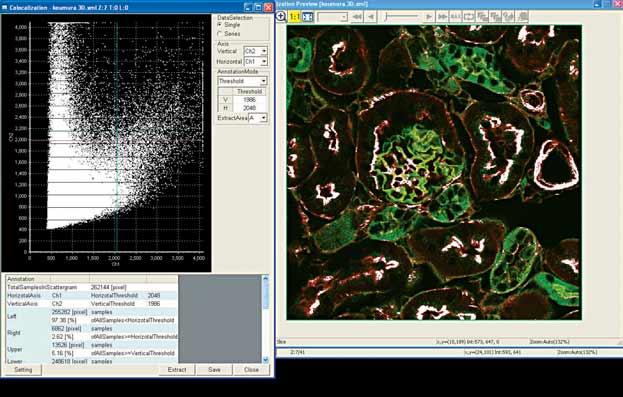
8 Application Broad Application Support and Sophisticated Experiment Control. Measurement Diffusion measurement and molecular interaction analysis. Photostimulation FRAP/FLIP/Photoactivation/Photoconversion/Uncaging. Measurement HDRi High Dynamic Range imaging Multi-Dimensional Time-Lapse Long-term and multiple point. 3D Mosaic Imaging High resolution images stitched to cover a large area. HDRi (High Dynamic Range imaging) Multiple images are captured using various acquisition conditions. The acquired image data are processed to create a single high-definition image with increased dynamic range, resulting in reduced saturation and emphasized low intensity signals. Photostimulation 3D/4D Volume Rendering HDRi Image Normal Image 3D/4D Volume Rendering One-click 3D/4D image construction from acquired XYZ/T images. Change the angle of 3D image with a single click. Multi- Dimensional Time-Lapse Colocalization Colocalization Configurable threshold values for fluorescence intensities on the scatterplot. Accurate colocalization statistics and visualization of colocalized area on image. 3D Mosaic Imaging FRET Intensity 2,400 2,200 2,000 1,800 1,600 1,400 1,200 1, CH1 CH2 CH1 CH2 FRET Configuration wizard simplifies the setting of FRET experimental procedures. Optimal laser excitation wavelengths for CFP/YFP FRET ,000 15,000 20,000 30,000 Time (ms) 35,000 40,000 Image of variations in calcium concentration of HeLa cells expressing YC3.60 when stimulated with histamine. Reference: Takeharu Nagai, Shuichi Yamada, Takashi Tominaga, Michinori Ichikawa, and Atsushi Miyawaki , PNAS, July 20, 2004, vol. 101, no


.")


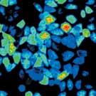
9 Application/ Molecular Interaction Analysis Diffusion Measurement Package Pixels RICS Application and Principles This optional software module enables data acquisition and analysis to investigate the molecular interaction and concentrations by calculating the diffusion coefficients of molecules within the cell. Diverse analysis methods (RICS/ccRICS, point FCS/point FCCS and FRAP) cover a wide range of molecular sizes and speeds. 0 Comparison of Diffusion Coefficients for EGFP Fusion Proteins Near to Cell Membranes and In Cytoplasm Pixels RICS can be used to designate and analyze regions of interest based on acquired images. EGFP is fused at protein kinase C (PKC) for visualization, using live cells to analyze the translocation with RICS. The diffusion coefficient close to cell membranes was confirmed to be lower than in cytoplasm, after stimulation with phorbol myristate acetate (PMA). This is thought to be from the mutual interaction between PKC and cell membrane molecules in cell membranes. In addition to localization of molecules, RICS analysis can simultaneously determine changes in diffusion coefficient, for detailed analysis of various intracellular signaling proteins. 130 RICS Raster Image Correlation Spectroscopy Raster image correlation spectroscopy (RICS) is a new method for analyzing the diffusion and binding dynamics of molecules in an entire, single image. RICS uses a spatial correlation algorithm to calculate diffusion coefficients and the number of molecules in specified regions. Cross correlation RICS (ccrics) characterizes molecular interactions using fluorescentlabeled molecules in two colors. At cytoplasmic membrane In cytoplasm Diffusion coefficient D =0.98 µm2/s Diffusion coefficient D =3.37 µm2/s Sample image: HeLa cells expressing EGFP fusion PKC (after PMA stimulation) RICS Principle Scan in X-Axis Direction Molecules of different sizes diffuse at different speeds within cells. Small molecules move faster, compared with large molecules that move relatively slowly. The FV1000 acquires information on the movement of these diffusing fluorescentlabeled molecules as image data, together with morphological information about the cell. The image data obtained for each pixel was sampled at different times, so the data for each pixel is affected by the passage of time, in addition to its spatial XY information. By analyzing this image data with a new statistical algorithm for spatial correlation, the diffusion coefficients and molecule counts can be calculated for molecules moving within the cell. Point FCS Point scan Fluorescence Correlation Spectroscopy Point scan fluorescence correlation spectroscopy (point FCS) analyzes intensity fluctuations caused by diffusion or binding/unbinding interactions of a protein complex. point FCS uses an auto correlation function to carry out operations on fluorescence signals obtained by continuous scanning of a single pixel on the screen. Point scan fluorescence cross-correlation spectroscopy (point FCCS) analyzes the fluctuation of fluorescent-labeled molecules in two colors. The coincidence of fluctuations occurring in two detection channels shows that the two proteins are part of the same complex. Point FCS and point FCCS can now be performed with a standard detector, eliminating the need for a special high-sensitivity detector. 0 µs 10 µs 20 µs 30 µs 40 µs 50 µs n µs 0 ms Scan in Y-Axis Direction 0 ms 1 ms 2 ms FRAP Analysis The Axelrod analytical algorithm is installed as a FRAP analysis method. The algorithm is used to calculate diffusion coefficients and the proportions of diffusing molecules. Analytical methods according to molecule diffusion speeds Small molecules in solution Proteins in solution Diffusion of proteins in cell Lateral diffusion in cell membrane Protein trafficking Spatial Correlation Algorithm When the spatial correlation algorithm is applied between pixels, a higher correlation is obtained as the speed of movement of the molecule nears the scanning speed. When calculating the spatial correlation in the X-direction, because the scanning speed in the X-direction is fast, a higher correlation is obtained for fast-moving molecules than for slow-moving molecules. When the scanning speed in the Ydirection is slow, a higher correlation is obtained for slow-moving molecules. RICS using LSM images scans in both X- and Y-directions, so it can be used to analyze the movements of a wide range of molecules, both fast and slow. 3 ms 4 ms n ms Small Molecular complex formation, aggregation Molecule size Large RICS Analysis Method Results of Analysis (diffusion coefficient and molecule count) > 100 Capable range of measurement ~ ~ 100 Point FCS RICS FRAP < 0.1 < 0.01 << LSM Image 15 Spatial Correlation Theoretical Formula Used for Fitting Calculation 16

 combines imaging with continuous bleaching of a specific region to observe the diffusion of a target")


 405 nm Specimen: HeLa cell, GFP (free), 488 nm excitation (multi-argon laser) Image acquisition time: 100 ms/ bleach time: 100 s continuously, 405 nm bleaching FRAP")
 is used to observe the gradual recovery of fluorescence intensity caused by protein diffusion from the area surrounding the bleached")


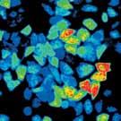
10 Application/ Molecular Interaction Analysis Photostimulation The SIM scanner system combines the main scanner with a photostimulation scanner. Control of the two independent beams enables simultaneous stimulation and imaging, to capture reactions during stimulation. Multi-stimulation software is used to continuously stimulate multiple points with laser light for simultaneous imaging of the effects of stimulation on the cell. FLIP Fluorescence Loss in Photobleaching Fluorescence loss in photobleaching (FLIP) combines imaging with continuous bleaching of a specific region to observe the diffusion of a target protein within a cell. The changes in the image over time make it possible to observe the location of structural bodies that inhibit the diffusion of the molecule. Photoconversion The Kaede protein is a typical photoconvertible protein, which is a specialized fluorescent protein that changes color when exposed to light of a specific wavelength. When the Kaede protein is exposed to laser light, its fluorescence changes from green to red. This phenomenon can be used to mark individual Kaede-expressing target cells among a group of cells, by exposing them to laser light. 405 nm laser light 3,000 2,800 2,600 2, nm 2,200 2,000 1,800 Intensity 1,600 1,400 1,200 1, ,000 20,000 30,000 40,000 50,000 60,000 70,000 80,000 90, ,000 Time (ms) 405 nm Specimen: HeLa cell, GFP (free), 488 nm excitation (multi-argon laser) Image acquisition time: 100 ms/ bleach time: 100 s continuously, 405 nm bleaching FRAP Fluorescence Recovery after Photobleaching Exposure of fluorescent-labeled target proteins to strong laser light causes their fluorescence to fade locally. Fluorescence recovery after photobleaching (FRAP) is used to observe the gradual recovery of fluorescence intensity caused by protein diffusion from the area surrounding the bleached region. By examining the resulting images, it is possible to characterize the diffusion speed of the molecule, and the speed of binding and release between the molecule and cell structures. Before Stimulation After Stimulation Kaede-expressing astroglia cells are stacked on the Kaede-expressing neurons. By illuminating two colonies with a 405 nm laser, the Kaede color can be photoconverted from green to red. The glial cells in contact with the neurons are observed while they are forming colonies and extending their processes, and the nuclei of these colonies can also be observed. The SIM scanner FV1000 makes it easy to change cell colors from green to red while conducting an observation, and to control neutral colors between red and green. Data courtesy of: Dr. Hiroshi Hama, Ms. Ryoko Ando and Dr. Atsushi Miyawaki, RIKEN Brain Science Institute Laboratory for Cell Function Dynamics Uncaging A 405nm laser is optional for uncaging with the SIM scanner system. Caged compounds can be uncaged point-by-point or within a region of interest, while the main scanner of the FV1000 captures images of the response with no time delay. 2,000 1,900 1,800 1,700 1,600 1,500 Fluorescent intensity Time Example: Fluorescence recovery without interactions If the protein can freely diffuse, the bleached region recovers its fluorescence at a high speed due to Brownian motion. Fluorescent intensity Time Example: Fluorescence recovery with interactions If the protein is strongly bound to a structure or forms part of a large protein complex, the bleached region recovers its fluorescence at a slower rate relative to the unbound state. Intensity Caged-Glutamate Fluorescent calcium indicator Fluo-3 in HeLa cells. Image acquisition at 1-second intervals Using the caged compound Bhcmoc-Glutamate, an increase in calcium ion concentration inside the cell can be observed in response to glutamate stimulation, released via 405 nm laser illumination. Data courtesy of: Dr. Hiroshi Hama, Dr. Atsushi Miyawaki, RIKEN Brain Science Institute Laboratory for Cell Function Dynamics Caged compound Bhcmoc-Glutamate presented by Dr. Toshiaki Furuta, Department of Science, Toho University Intensity 1,400 1,300 1,200 1,100 1, ,000 10,000 20,000 15,000 30,000 25,000 35,000 Time (ms) 40,000 45,000 50,000 55, Specimen: Hippocampal neurons, Shank-GFP stain, 488 nm excitation (multi-argon laser) Image acquisition time: 100 ms Bleach time: 80 ms, 488 nm excitation (Sapphire 488 laser) Data courtesy of: Dr. Shigeo Okabe Department of Anatomy and Cell Biology, Tokyo Medical and Dental University ,000 20,000 30,000 40,000 50,000 Time (ms) 60,000 70,000 80,000 Multi-Point Photostimulation Using multi-stimulation software, the user can configure continuous photostimulation of multiple points with simultaneous imaging, which is effective for applications such as uncaging experiments involving photostimulation of several spines in neurons


: 32 x 38, 48")
11 Application/ Molecular Interaction Analysis P1 P5 P2 P4 P3 Multi-Dimensional Time-Lapse The FV1000 can be used for ideal multi-dimensional time-lapse imaging during confocal observation, using multi-area time-lapse software to control the motorized XY stage and focus compensation. 3D Mosaic Imaging Mosaic imaging is performed using a high-magnification objective to acquire continuous 3D (XYZ) images of adjacent fields of view using the motorized stage, utilizing proprietary software to assemble the images. The entire process from image acquisition to tiling can be fully automated. Significantly Improved Long Time-Lapse Throughput Equipped with motorized XY stage for repeated image acquisition from multiple points scattered across a wide area. The system efficiently analyzes changes over time of cells in several different areas capturing, large amounts of data during a single experiment to increase the efficiency of experiments. Microplates can be used to run parallel experiments, which significantly improves throughput for experiments that require long-term observation. Mosaic Imaging for 3D XYZ Construction Composite images are quickly and easily prepared using the stitching function, to form an image over a wide area. 3D construction can also be performed by acquiring images in the X, Y and Z directions. Tiled images can be enlarged in sections without losing resolution. Particularly useful for "Connectome" or "Brain Mapping" type projects requiring large area scanning at high resolution. Tiling functions include true stitching and smoothing options for improved seamless images. Supports repeated image acquisition from multiple areas in a single microplate well. Focal Plane 4 Focal Plane 3 Focal Plane 2 Focal Plane 1 Point 1 Point 2 Point 5 Point 3 Point 4 CNS markers in normal mice Objective : PLAPON60x Zoom : 2x Image acquisition numbers (XY): 32 x 38, 48 slices for each image Courtesy of: Dr. Mark Ellisman PhD, Hiroyuki Hakozaki, MS Mark Ellisman National Center for Microscopy and Imaging Research (NCMIR), University of California, San Diego Multi-Point Time-Lapse Software Point 6 Focal Drift Compensation for Long Time-Lapse Imaging The IX81-ZDC Zero Drift Compensation system corrects loss of focus caused by temperature changes around the microscope and other factors during long time-lapse observation. The thermal drift compensation eliminates the need to take images at several Z planes, minimizing live cell exposure to irradiation. Offset Objective focal plane IR Laser for focal plane detection Baseline focal plane Set target observation plane as offset. Over time, the objective focal plane drifts from the observation plane. Laser detects the glass surface before imaging. Immediately returns to initial offset plane, for focal drift compensation. ZDC Scanning unit Automated from 3D Image Acquisition to Mosaic Imaging Multi-area time-lapse software automates the process from 3D image acquisition (using the motorized XY stage) to stitching. The software can be used to easily register wide areas, and the thumbnail display provides a view of the entire image acquired during the mosaic imaging process. Maintain Cell Activity Over A Long Period CO2 incubator control keeps the environment inside the tissue culture dish completely stable. The environment is precisely maintained at 37 C with 90% humidity and 5% CO2 concentration. 0 s 1000 s 2000 s 3000 s 4000 s 5000 s 6000 s 7000 s Human lymphoblast cells TK6 Courtesy of: Masamitsu Honma, Dir. Biological Safety Research Center Div. of Genetics and Mutagenesis I, National Institute of Health Sciences 19 Coordinate Information 20 Thumbnail
12 Expandability Expandability to Support Diverse Application Application Molecular interaction and molecular concentration analysis Standard Functions Optional Functions Intracellular diffusion measurement Calculation of diffusion coefficients for intracellular molecules, and analysis of molecular binding and changes in molecular density. Supports a wide range of methods (RICS/ccRICS, point FCS/point FCCS and FRAP). Software Required: Diffusion measurement package 125 Pixels Pixels 130 Photostimulation Acquires images while rapidly switching the built-in laser between imaging and photostimulation. Features tornado scanning for highefficiency bleaching using laser light stimulation. SIM scanner system Performs simultaneous imaging and photostimulation. Provides detailed settings for photostimulation including position and timing. Features tornado scanning for high-efficiency bleaching using laser light stimulation. Equipment Required: SIM scanner, laser combiner (dual fiber version) P2 P3 P1 P4 Long time-lapse system Microscopes equipped with zero drift compensation (ZDC) acquire each image at a set focus plane. The microscope CO2 incubator maintains cell activity for a long period for continuous imaging. Equipment Required: IX81-ZDC microscope, CO2 incubator Multi-point scanning system Register multiple points for repeated image acquisition. Efficiently observe multiple cells in parallel on 35-mm dishes, microplates or chamber slides. Software and Equipment Required: Multi-area time-lapse software, motorized XY stage** TIRFM 3D mosaic imaging system Continuous imaging of adjacent fields of view and mosaic imaging to form a composite image. Acquisition of adjacent Z-series images for 3D mosaic imaging. Software and Equipment Required: Multipoint time-lapse software, motorized XY stage** TIRFM imaging Uses the laser from the laser combiner to provide evanescent illumination, for imaging the movement of molecules near the glass surface, such as cell membranes and adhesion factors. Software and Equipment Required: TIRFM unit*, TIRF objective, highsensitivity CCD camera**, CCD camera control software** FRET Provides FRET analysis functions. Diode laser offers exceptional stability and long life. Supports FRET efficiency measurements using acceptor photobleach method. CFP-YFP FRET Ratio imaging and sensitized emission. Available 440 nm diode laser is optimized for CFP-YFP FRET experiments methods. Diode laser offers exceptional stability and long life. Equipment Required: LD 440 nm Laser Multi-color imaging Three-channel detector for simultaneous acquisition of fluorescence images from three different dyes. Sequential mode for acquisition of fluorescence images without cross-talk. Fluorescence can also be separated using unmixing (only available on spectral scan unit). Imaging blue dyes Available 405-nm laser for image acquisition of multi-stained samples labeled with V-excitation fluorescent dyes such as DAPI, Hoechst and Alexa Fluor 405. Equipment Required: LD 405 nm laser Easily determine if labeled substances are present locally in the same locations. Calculation of Pearson coefficients, overlap coefficients and colocalization indices. High-accuracy colocalization analysis New 60x oil-immersion objective offers image acquisition with exceptional positional accuracy coefficient. Equipment Required: PLAPON 60xOSC Colocalization analysis LD ECFP furared EYFP EGFP Cy2 DiO YOYO-1 AzamiGreen fluo-4 FITC RhodamineGreen OregonGreen488 Alexa Fluor 488 AcridineOrange Calcium Green-1 fluo-3 MagnesiumGreen Kaede SNARF-1 PI CalciumOrange Cy3 MagnesiumOrange Dil TRITC rhod-2 Alexa Fluor 546 RhodaminePhalloidin DsRed2 Rhodamine Red-X Alexa Fluor 568 Cy3.5 MitoTracker X-rhod-1 mcherry HcRed1 Alexa Fluor 594 TexasRed Alexa Fluor 633 TOTO-3 Cy5 Alexa Fluor 647 Cy5.5 P5 3D mosaic imaging Hoechst33258 DAPI GFP-uv Multi-point photostimulation system Register multiple points for photostimulation, and program the respective stimulation order, stimulation time and type of stimulation (continuous laser light or pulsed laser light). Software Required: Multi-stimulation software Multi-dimensional time-lapse imaging 400 LD e n on on en rg rg go H r A A n A ti ti e lti ul ul re G LD LD M LD Mu M Simultaneous four-color imaging Fourth channel detector can be easily added to simultaneously acquire images of four colors. Equipment Required: 4-channel detector * SIM scanner and TIRFM scanner cannot be installed on the same system. ** For more information about peripheral equipment, contact your Olympus local representative *Selected fluorescence dyes, white dot shows the absorption maximum, graphs show the dye emission spectra


 laser. Scanning Unit for IX81 Inverted Microscope Dedicated mirror unit cassette is required.")

 F F D B E A G IX81 IX81-ZDC Inverted motorized microscope Scanning unit for BX61WI, BX61 (Spectral type or Filter type detector system) G CO2 incubator * Motorized XY stage * G Cover * TIRFM")


13 Expandability Scanning Units Two types of scanning units, filter-based and spectral detection, are provided. The design is all-in-one, integrating the scanning unit, tube lens and pupil projection lens. Use of the microscope fluorescence illuminator light path ensures that expandability of the microscope itself is not limited. Visible, UV and IR laser introduction ports are provided, as well as a feedback control system. Laser Systems The multi-combiner enables combinations with all of the following diode lasers: 405 nm, 440 nm, 473 nm, 559 nm and 635 nm. The system can also be equipped with conventional Multi-line Ar laser and HeNe(G) laser. Scanning Unit for IX81 Inverted Microscope Dedicated mirror unit cassette is required. Scanning Unit for BX61/BX61WI Upright Microscopes Fluorescence illuminator integrated with scanning unit. FV1000 System Diagram Fluorescence illumination unit LD635 laser 635 nm LD559 laser 559 nm HeNeG laser 543 nm Select either laser Multi Ar laser 458, 488, 515 nm LD473 laser 473 nm Select either laser LD440 laser* 440 nm LD405 laser* 405 nm A AOTF Laser combiner (Single-fiber type) AOTF Laser combiner (Dual-fiber type) B B C Scanning unit for IX81 (Spectral type or Filter type detector system ) F F D B E A G IX81 IX81-ZDC Inverted motorized microscope Scanning unit for BX61WI, BX61 (Spectral type or Filter type detector system) G CO2 incubator * Motorized XY stage * G Cover * TIRFM unit * SIM Scanner* Illumination Units Conventional illumination modules are designed for long-duration time-lapse experiments. Since light is introduced through fiber delivery systems, no heat is transferred to the microscope. Dual Type The multi-combiner outputs laser light with two fibers. Light can be used both for observation and photostimulation. Fluorescence Illumination Unit Stand with Mercury lamp house, motorized shutter, and fiber delivery system for conventional fluorescence observation. Light introduction via fiber optic port. Single Type Single channel laser output. AOTF is standard equipment. Transmitted Light Detection Unit External transmitted light photomultiplier detector and 100 W Halogen conventional illumination, integrated for both laser scanning and conventional transmitted light Nomarski DIC observation. Motorized exchange between transmitted light illumination and laser detection. Simultaneous multi-channel confocal fluorescence image and transmitted DIC acquisition enabled. IR laser* Transmitted light detection unit Fiber port for fluorescence output* 4th channel detector unit* *Optional unit D E F FV power supply unit D Microscope control unit B E A FV control unit BX61WI BX61 Upright motorized microscope Software Basic software Review station software * Diffusion Measurement Package * Multi Stimulation Software * Multi Area Time Lapse Software * C FV Power supply * Monitor Optional Upgrade Equipments for FV1000 4th Channel Detector Unit Attaches to the optional port of either the filter or spectral type scanning unit and is used as a 4th confocal fluorescence detection channel. This is a filter-based fluorescence detection unit. SIM Scanner Second scanner dedicated for photostimulation, synchronized to the FV1000 main scanner for simultaneous photostimulation and confocal image acquisition. Independent fiber optic laser introduction port. Dichromatic mirror within motorized optical port of the scan unit required for introduction of laser into main scanner. TIRFM Unit Enables control of the necessary volume of excitation light using FV1000 software. This unit enables TIRF imaging using the laser light source used with Confocal. Fiber Port for Fluorescence Output Confocal fluorescence emission can be introduced via fiber delivery system into external device. Fiber port equipped with FC connector (fiber delivery system not included). IX81-ZDC Focal drift compensation for long timelapse imaging. * Requires IX81 microscope. For information about ZDCcompatible objectives, contact your Olympus dealer. CO2 Incubator/ MIU-IBC-IF-2, MIU-IBC-I-2 Highly precise incubator control keeps the environment inside a laboratory dish completely stable, at just below 37 C temperature, 90% moisture and 5% CO2 concentration; in this way, live cell activity can be maintained for approximately two days. * Not available in some areas High-Precision Motorized Stage/ PRIOR H117 Multi-point time-lapse photography using a 35 mm glass-bottom dish is easy to perform with this motorized stage, which can reproduce previouslyset positions with extreme precision. It also allows efficient photographing of multiple cells and detection of individual cells showing expected reactions
, HeNe(G) laser (543 nm, 1 mw) AOTF Laser Combiner Visible light laser platform with implemented AOTF system, Ultra-fast intensity modulation")
14 Expandability Main Specifications Spectral Version Filter Version Laser Light Violet/Visible Light Laser LD lasers: 405 nm: 50 mw, 440 nm: 25 mw, 473 nm: 15 mw, 559 nm: 15 mw, 635 nm, 20 mw Multi-line Ar laser (458 nm, 488 nm, 515 nm, Total 30 mw), HeNe(G) laser (543 nm, 1 mw) AOTF Laser Combiner Visible light laser platform with implemented AOTF system, Ultra-fast intensity modulation with individual laser lines, additional shutter control Continuously variable (0.1% 100%, 0.1% increment), REX: Capable of laser intensity adjustment and laser wavelength selection for each region Fiber Broadband type (400 nm 650 nm) Scanning and Scanner Module Standard 3 laser ports, Violet to IR Detection Excitation dichromatic mirror turret, 6 position (High performance DMs and 20/80 half mirror), Dual galvanometer mirror scanner (X, Y) Motorized optical port for fluorescence illumination and optional module adaptation, Adaptation to microscope fluorescence condenser Detector Module Standard 3 confocal Channels (3 photomultiplier detectors) Standard 3 confocal Channels (3 photomultiplier detectors) Additional optional output port light path available for optional units Additional optional output port light path available for optional units 6 position beamsplitter turrets with CH1 and CH2 6 position beamsplitter turrets with CH1 and CH2 CH1 and CH2 equipped with independent grating and slit for fast and CH1 to CH3 each with 6 position barrier filter turret flexible spectral detection (High performance filters) Selectable wavelength bandwidth: nm Wavelength resolution: 2 nm Wavelength switching speed: 100 nm/ms CH3 with 6 position barrier filter turret Filters High performance sputtered filters, dichromatic mirrors and barrier filters Scanning Method 2 galvanometer scanning mirrors Scanning Modes Scanning speed: 512 x 512 (1.1 s, 1.6 s, 2.7 s, 3.3 s, 3.9 s, 5.9 s, 11.3 s, 27.4 s, 54.0 s) bidirectional scanning 256 x 256 (0.064 s, s), 512 x 512 (0.254 s) X,Y,T,Z,λ X,Y,T,Z Line scanning: Straight line with free orientation, free line, Point scanning Line scanning: Straight line with free orientation, free line, Point scanning Photo Detection Method 2 detection modes: Analog integration and hybrid photon counting Pinhole Single motorized pinhole Single motorized pinhole pinhole diameter ø µm (1 µm step) pinhole diameter ø µm (1 µm step) Field Number (NA) 18 Optical Zoom 1x 50x in 0.1x increment Z-drive Integrated motorized focus module of the microscope, minimum increment 0.01 µm or 10 nm Transmitted Light Module with integrated external transmitted light photomultiplier detector and 100 W Halogen lamp, motorized switching, fiber adaptation to microscope Detector unit frame Microscope Motorized Microscope Inverted IX81, Upright BX61, Upright focusing nosepiece & fixed stage BX61WI Fluorescence Illumination External fluorescence light source with motorized shutter, fiber adaptation to optical port of scan unit Unit Motorized switching between LSM light path and fluorescence illumination System Control Control Unit OS: Windows 7 Professional (English version) 32 bit, CPU: Intel Core i7-870 (2.93 GHz) or higher, Memory: 4 GB (1 GBx4), Hard disk: 1 TB or more for data storage, Dedicated I/F board: built-in control unit, Graphics board: ATI Radeon HD 5570, Optical drive: DVD-RAM ± R/RW Power Supply Unit Galvo control boards, scanning mirrors and gratings, Real time controller Galvo control boards, scanning mirrors Display SXGA 1280X1024, dual 19 inch (or larger) monitors or WQUXGA 2560 x 1600, 29.8 inch monitor Optional Unit SIM Scanner 2 galvanometer scanning mirrors, pupil projection lens, built-in laser shutter, 1 laser port, Fiber introduction of near UV diode laser or visible light laser, Optional: 2nd AOTF laser combiner TIRFM Unit Available laser: nm. Motorized penetration ratio adjustment. Automatic optical setting for TIRFM objectives Fourth Confocal Detector Module with photomultiplier detector, barrier filter turret, beamsplitter turret mounted with 3rd CH light path Fiber Port for Fluorescence Output port equipped with FC fiber connector (compatible fiber core µm) Dimensions, Weight and Power Consumption Dimensions (mm) Weight (kg) Power consumption Microscope with scan unit BX61/BX61WI 320 (W) x 580 (D) x 565 (H) 41 IX (W) x 750 (D) x 640 (H) 51 Fluorescence illumination unit Lamp 180 (W) x 320 (D) x 235 (H) 6.7 Power supply 90 (W) x 270 (D) x 180 (H) 3.0 AC V 50/60 Hz 1.6 A Transmitted light detection unit 170 (W) x 330 (D) x 130 (H) 5.9 Microscope control unit 125 (W) x 332 (D) x 216 (H) 5.2 AC / V 50/60 Hz 3.5 A/1.5 A FV Power supply unit 180 (W) x 328 (D) x 424 (H) 7.5 AC / V 50/60 Hz 4.0 A/2.0 A FV control unit 136 (W) x 380 (D) x 329 (H) 8.5 AC 100/240 V 50/60 Hz 300 W Display 19 inch, dual (value per monitor) 363 (W) x 216 (D) x (H) 5.9 AC / V 50/60 Hz 0.65 A/0.4 A 29.8 inch 689 (W) x (D) x (H) 15.7 AC / V 50/60Hz 1.8 A/0.8 A Power supply unit for laser combiner 210 (W) x 300(D) x 100 (H) 4.0 AC / V 50/60 Hz 2.0 A/1.0 A Laser combiner (with Ar laser heads) 514 (W) x 504 (D) x 236 (H) 45 Laser combiner (without Ar laser heads) 514 (W) x 364 (D) x 236 (H) 40 LD559 laser power supply 200 (W) x 330 (D) x 52 (H) 1.2 AC V 50/60 Hz 30 W Multi Ar laser power supply 162 (W) x 287 (D) x 91 (H) 4.4 AC V 50/60 Hz 20 A HeNe(G) laser power supply 130 (W) x 224 (D) x 62 (H) 1.8 AC V 50/60 Hz 0.45 A Recommended FV1000 system setup (IX81, BX61, BX61WI) (unit: mm) Software Image Acquisition Normal scan: 64 x 64, 128 x 128, 256 x 256, 320 x 320, 512 x 512, 640 x 640, 800 x 800, 1024 x 1024, 1600 x 1600, 2048 x 2048, 4096 x 4096 Clip rectangle scan,clip ellipse scan,polygon clip scan,line scan,free line scan,point scan, Real-time image 2-dimension: XY, XZ, XT and Xλ 3-dimension: XYZ, XYT, XYλ, XZT, XTλ and XZλ 4-dimension: XYZT, XZTλ and XYTλ 5 dimension: XYZTλ Programmable Scan Controller Time Controller function 2D Image Display Each image display: Single-channel side-by-side, merge, cropping, live tiling, live tile, series (Z/T/λ), LUT: individual color setting, pseudo-color, comment: graphic and text input 3D Visualization and Observation Interactive volume rendering: volume rendering display, projection display, animation displayed (save as OIF, AVI or MOV format) Free orientation of cross section display 3D animation (maximum intensity projection method, SUM method) 3D and 2D sequential operation function Image Format OIB/ OIF image format 8/ 16 bit gray scale/index color, 24/ 32/ 48 bit color, JPEG/ BMP/ TIFF/ AVI/ MOV image functions Olympus multi-tif format Spectral Unmixing 2 Fluorescence spectral unmixing modes (normal and blind mode) Image Processing Filter type: Sharpen, Average, DIC Sobel, Median, Shading, Laplacian Calculations: inter-image, mathematical and logical, DIC background leveling Image Analysis Fluorescence intensity, area and perimeter measurement, time-lapse measurement Statistical Processing 2D data histogram display, colocalization Optional Software Review station software, Off-line FLUOVIEW software for date analysis. Motorized stage control software, Diffusion measurement package, Multi stimulation software, Multi area time-lapse software Depth: 990 Objectives for BX2 and IX2 (using U-UCD8A-2, IX2-LWUCDA2 and U-DICTS) Cover glass Condenser for BX2 Condenser for IX2 Model NA W.D. thickness Immersion Correction (mm) liquid ring U-UCD8A-2 IX2-LWUCDA2 (mm) optical element optical element U-DICTS position UPLSAPO4X UPLSAPO10X U-DIC10 IX2-DIC10 normal UPLSAPO20X U-DIC20 IX2-DIC20 normal UPLSAPO20XO Oil U-DIC20 IX2-DIC20 normal UPLSAPO30XS Silicone U-DIC60HC IX2-DIC30 normal UPLSAPO40X _ U-DIC40 IX2-DIC40 normal UPLSAPO60XO Oil U-DIC60 IX2-DIC60 BFP1 UPLSAPO60XW Water _ U-DIC60 IX2-DIC60 normal UPLSAPO60XS Silicone _ U-DIC60 IX2-DIC60 normal UPLSAPO100XO Oil U-DIC100 IX2-DIC100 normal PLAPON60XO Oil U-DIC60 IX2-DIC60 BFP1 PLAPON60XOSC Oil U-DIC60 IX2-DIC60 BFP1 UPLFLN40XO Oil U-DIC40 IX2-DIC40 BFP1 APON60XOTIRF Oil _ U-DIC60 IX2-DIC60 BFP1 UAPON100XOTIRF Oil _ U-DIC100 IX2-DIC100 normal UAPON150XOTIRF Oil _ U-DIC100 IX2-DIC100 normal Apo100XOHR Oil U-DIC100 IX2-DIC100 normal Objectives for fixed stage upright microscope (using WI-UCD, WI-DICTHRA2) Model NA W.D. (mm) DIC prism Revolving nosepiece MPLN5X WI-SSNP, WI-SRE3 UMPLFLN10XW WI-DIC10HR WI-SSNP, WI-SRE3 UMPLFLN20XW WI-DIC20HR WI-SSNP, WI-SRE3 LUMPLFLN40XW WI-DIC40HR WI-SSNP, WI-SRE3 LUMPLFLN60XW WI-DIC60HR WI-SSNP, WI-SRE3 LUMFLN60XW WI-DIC60HR WI-SSNP, WI-SRE3 XLUMPLFLN20XW 1.00 * 2.0 WI-DICXLU20HR WI-SNPXLU2 * Note: These conditions are not met in confocal microscopy Images are courtesy of the following institutions: "Brainbow" mouse brain stem Courtesy of the laboratories of Jeff W. Lichtman and Joshua R. Sanes Harvard University MCB Department and the Center for Brain Science Hippocampal neurons Courtesy of Dr. Shigeo Okabe Department of Cellular Neurobiology, Graduate School of Medicine, The University of Tokyo Cultured nerve cells derived from the mouse hippocampus Courtesy of Dr. Koji Ikegami, Dr. Mitsutoshi Setou Molecular Geriatric Medicine, Mitsubishi Kagaku Institute of Life Sciences Cerebellum Purkinje cell Courtesy of Dr. Tetsuro Kashiwabara, Assistant Professor; and Dr. Akira Mizoguchi, Professor; Neuroregenerative medicine course, Mie University School of Medicine Drosophila, Stage 14 Courtesy of Dr. Tetsuya Kojima Laboratory of Innovational Biology, Department of Integrated Biosciences Graduate School of Frontier Sciences, University of Tokyo Mouse brain section Courtesy of Mr. Masayuki Sekiguchi (Section Chief) Department of Degenerative Neurological Diseases, National Institute of Neuroscience, National Center of Neurology and Psychiatry Rudimentary limbs of larva in latter part of 3rd instar Courtesy of Dr. Tetsuya Kojima Laboratory of Innovational Biology, Department of Integrated Biosciences, Graduate School of Frontier Sciences, University of Tokyo Zebrafish Courtesy of Dr. Toru Murakami, Department of Neuromuscular & Developmental Anatomy, Gunma University Graduate School of Medicine Medaka embryogenesis (somite stage) Courtesy of Minoru Tanaka, Hiromi Kurokawa National Institute for Basic Biology Laboratory of Molecular Genetics for Reproduction Pilidium larva of Micrura alaskensis Courtesy of Dr. Svetlana Maslakova of the University of Washington and Dr. Mikhail V Matz of the Whitney Laboratory for Marine Bioscience, University of Florida. Osteoclast induced from rat monocyte in rat kidney Courtesy of Dr. Keiko Suzuki, Department of Pharmacology, Showa University School of Dentistry Fucci Sliced mouse brain, expressing S/G2/M phases Courtesy of Dr. Hiroshi Kurokawa, Dr. Asako Sakaue-Sawano and Dr. Atsushi Miyawaki RIKEN Brain Science Institute Laboratory for Cell Function Dynamics Wild-type embryo in stage 17 of drosophila Courtesy of Dr. Tetsuya Kojima Laboratory of Innovational Biology, Department of Integrated Biosciences Graduate School of Frontier Sciences, University of Tokyo Alpha Blend method (Cultured nerve cells derived from the mouse hippocampus) Courtesy of Dr. Koji Ikegami, Dr. Mitsutoshi Setou Molecular Geriatric Medicine, Mitsubishi Kagaku Institute of Life Sciences 25 26
Confocal Laser Scanning Biological Microscope FV1000 FLUOVIEW. FLUOVIEW Always Evolving
 FLUOVIEW Always Evolving Confocal Laser Scanning Biological Microscope FV1000 FLUOVIEW 1 FLUOVIEW From Olympus is Open FLUOVIEW More Advanced than Ever The Olympus FLUOVIEW FV1000 confocal laser scanning
Quality Performance, Innovative Design
 Dimensions Confocal Laser Scanning Biological Microscope Table size (mm): 1400(W) 800(D) * Table is not available from Olympus. Avoid placing the controller directly on the floor. Dimensions / Weight /
 07 Setting Place a specimen, and select a fluorescence dye. The FV10i automatically selects the most suitable imaging conditions based on the fluorescence dye selection. Set Image mapping menu Just click
FV1200 FLUOVIEW. High-Performance Laser Scanning Microscope for Live Cell Imaging Combining Accuracy, Sensitivity and Laser Stimulation
 Images are courtesy of the following institutions: Dopaminergic neural circuits of the fruit fly Drosophila brain (adult female). Three-channel antibody labeling of the brain in which an expression driver
Opterra. Multipoint Scanning Confocal Microscope. Innovation with Integrity. Cell-Friendly, High-Speed, High-Resolution Imaging
 Opterra Multipoint Scanning Confocal Microscope Cell-Friendly, High-Speed, High-Resolution Imaging Innovation with Integrity Fluorescence Microscopy Opterra Multipoint Scanning Confocal Microscope Superior
LSM 510 META in Chang Gung University
 Content LSM 510 META in Chang ung University LSM 510 META 路 理 The features and applications of LSM 510 META 01-09 Introduction of the hardware 10-12 Fluorescence observation in conventional microscope
Multifluorescence The Crosstalk Problem and Its Solution
 Multifluorescence The Crosstalk Problem and Its Solution If a specimen is labeled with more than one fluorochrome, each image channel should only show the emission signal of one of them. If, in a specimen
Why and How? Daniel Gitler Dept. of Physiology Ben-Gurion University of the Negev. Microscopy course, Michmoret Dec 2005
 Why and How? Daniel Gitler Dept. of Physiology Ben-Gurion University of the Negev Why use confocal microscopy? Principles of the laser scanning confocal microscope. Image resolution. Manipulating the
Confocal Microscopy. Kristin Jensen
 Confocal Microscopy Kristin Jensen 17.11.05 References Cell Biological Applications of Confocal Microscopy, Brian Matsumoto, chapter 1 Studying protein dynamics in living cells,, Jennifer Lippincott-Schwartz
Opterra II Multipoint Scanning Confocal Microscope. Innovation with Integrity
 Opterra II Multipoint Scanning Confocal Microscope Enabling 4D Live-Cell Fluorescence Imaging through Speed, Sensitivity, Viability and Simplicity Innovation with Integrity Fluorescence Microscopy The
Working Simultaneously. The Next Level of TIRF Microscopy. cell^tirf Illuminator Motorized Total Internal Reflection Fluorescence
 cell^tirf Illuminator Motorized Total Internal Reflection Fluorescence Four individually aligned illumination beams for simultaneous multi-color TIRF imaging Working Simultaneously The Next Level of TIRF
The Next Level of TIRF Microscopy. cell^tirf Illuminator Motorized Total Internal Reflection Fluorescence
 cell^tirf Illuminator Motorized Total Internal Reflection Fluorescence Four individually aligned illumination beams for simultaneous multi-color TIRF imaging The Next Level of TIRF Microscopy Mario Faretta,
Quick Start Guide. Leica SP5 X
 Quick Start Guide Leica SP5 X Please note: Some of the information in this guide was taken from Leica Microsystems Leica TCS SP5 LAS AF Guide for New Users. This work is licensed under the Creative Commons
ADVANCED METHODS FOR CONFOCAL MICROSCOPY II. Jean-Yves Chatton Sept. 2006
 ADVANCED METHODS FOR CONFOCAL MICROSCOPY II Jean-Yves Chatton Sept. 2006 Workshop outline Confocal microscopy of living cells and tissues X-Z scanning Time series Bleach: FRAP, photoactivation Emission
Things to check before start-up.
 Byeong Cha Page 1 11/24/2009 Manual for Leica SP2 Confocal Microscope Enter you name, the date, the time, and the account number in the user log book. Things to check before start-up. Make sure that your
Zeiss 780 Training Notes
 Zeiss 780 Training Notes Turn on Main Switch, System PC and Components Switches 780 Start up sequence Do you need the argon laser (458, 488, 514 nm lines)? Yes Turn on the laser s main power switch and
Training Guide for Leica SP8 Confocal/Multiphoton Microscope
 Training Guide for Leica SP8 Confocal/Multiphoton Microscope LAS AF v3.3 Optical Imaging & Vital Microscopy Core Baylor College of Medicine (2017) Power ON Routine 1 2 Turn ON power switch for epifluorescence
Leica TCS SP8 Quick Start Guide
 Leica TCS SP8 Quick Start Guide Leica TCS SP8 System Overview Start-Up Procedure 1. Turn on the CTR Control Box, Fluorescent Light for the microscope stand. 2. Turn on the Scanner Power (1) on the front
Spectral Imaging with the Opterra Multipoint Scanning Confocal
 Spectral Imaging with the Opterra Multipoint Scanning Confocal Outline Opterra design overview Scan Modes Light Path Spectral Imaging with Opterra Drosophila larva heart. Opterra Design Overview Supravideo
Last updated: May 2014 Y.DeGraaf
 FLINDERS MICROSCOPY BIOMEDICAL SERVICES AVAILABLE MICROSCOPES AND SPECIFICATIONS & INFORMATION REGARDING TRAINING FOR NEW USERS Last updated: May 2014 Y.DeGraaf If you have new staff or students (Honours/Masters
長庚大學共軛焦顯微鏡課程 長庚大學共軛焦顯微鏡課程. Spot light 長庚大學
 長庚大學共軛焦顯微鏡課程 Spot light 長庚大學共軛焦顯微鏡課程 20071030 長庚大學 Basic principle of Laser Scanning Confocal Microscopy The application of LSM 510 META detector Multiphoton microscopy basic principle and introduction
Confocal imaging on the Leica TCS SP8. 1) Turn the system on. 2) Use TCS user account. 3) Start LAS X software:
 Turn the system on. 2) Use TCS user account. 3) Start LAS X software:") Confocal imaging on the Leica TCS SP8 1) Turn the system on. 2) Use TCS user account. 3) Start LAS X software: 4) Do not touch the microscope while the software is initializing. Choose your options: Turn
Confocal imaging on the Leica TCS SP8 1) Turn the system on. 2) Use TCS user account. 3) Start LAS X software: 4) Do not touch the microscope while the software is initializing. Choose your options: Turn
TRAINING MANUAL. Olympus FV1000
 TRAINING MANUAL Olympus FV1000 September 2014 TABLE OF CONTENTS A. Start-Up Procedure... 1 B. Visual Observation under the Microscope... 1 C. Image Acquisition... 4 A brief Overview of the Settings...
LEICA TCS SP5 AOBS TANDEM USER MANUAL
 LEICA TCS SP5 AOBS TANDEM USER MANUAL STARTING THE SYSTEM...2 THE LAS AF SOFTWARE...3 THE «ACQUIRE» MENU...5 CHOOSE AND CREATE A SETTING...6 THE CONTROL PANEL...8 THE DMI6000B MICROSCOPE...10 ACQUIRE ONE
Practical work no. 3: Confocal Live Cell Microscopy
 Practical work no. 3: Confocal Live Cell Microscopy Course Instructor: Mikko Liljeström (MIU) 1 Background Confocal microscopy: The main idea behind confocality is that it suppresses the signal outside
Leica TCS SP8 Quick Start Guide
 Leica TCS SP8 Quick Start Guide Leica TCS SP8 System Overview Start-Up Procedure 1. Turn on the CTR Control Box, EL6000 fluorescent light source for the microscope stand. 2. Turn on the Scanner Power
Olympus Fluoview 1000S Spectral Confocal Microscope Introduction to the NRI-MCDB Microscopy Facility Spectral Confocal Microscope
 Olympus Fluoview 1000S Spectral Confocal Microscope Introduction to the NRI-MCDB Microscopy Facility Spectral Confocal Microscope Improved Optics More Lasers 405 diode 440 diode 488 Argon 515 Argon 559
Training Guide for Carl Zeiss LSM 510 META Confocal Microscope
 Training Guide for Carl Zeiss LSM 510 META Confocal Microscope AIM 4.2 Optical Imaging & Vital Microscopy Core Baylor College of Medicine (2017) Power ON Routine 1 2 Turn ON Components and System/PC switches
Guide to Confocal 5. Starting session
 Guide to Confocal 5 Remember that when booking and before starting session you can check for any problems at https://www.bris.ac.uk/biochemistry/uobonly/cif/index.html Starting session Switch on microscope
Travel to New Dimensions- LSM 880. The Resolution of a Microscope is limited. The Resolution of a Microscope is limited. Image. Image. Object.
 Travel to New Dimensions- LSM 880 LSM 880: The Power of Sensitivity Our Latest Member of the LSM 880 with GaAsP Detectors Sensitivity, and Ease of Use Innovative High-End Laser Scanning Microscopes from
Zeiss 880 Training Notes Zen 2.3
 Zeiss 880 Training Notes Zen 2.3 1 Turn on the HXP 120V Lamp 2 Turn on Main Power Switch Turn on the Systems PC Switch Turn on the Components Switch. 3 4 5 Turn on the PC and log into your account. Start
Supplemental Figure 1: Histogram of 63x Objective Lens z axis Calculated Resolutions. Results from the MetroloJ z axis fits for 5 beads from each
 Supplemental Figure 1: Histogram of 63x Objective Lens z axis Calculated Resolutions. Results from the MetroloJ z axis fits for 5 beads from each lens with a 1 Airy unit pinhole setting. Many water lenses
Training Guide for Carl Zeiss LSM 5 LIVE Confocal Microscope
 Training Guide for Carl Zeiss LSM 5 LIVE Confocal Microscope AIM 4.2 Optical Imaging & Vital Microscopy Core Baylor College of Medicine (2017) Power ON Routine 1 2 Verify that main power switches on the
Boulevard du Temple Daguerrotype (Paris,1838) a busy street? Nyquist sampling for movement
 a busy street? Nyquist sampling for movement") Boulevard du Temple Daguerrotype (Paris,1838) a busy street? Nyquist sampling for movement CONFOCAL MICROSCOPY BioVis Uppsala, 2017 Jeremy Adler Matyas Molnar Dirk Pacholsky Widefield & Confocal Microscopy
Boulevard du Temple Daguerrotype (Paris,1838) a busy street? Nyquist sampling for movement CONFOCAL MICROSCOPY BioVis Uppsala, 2017 Jeremy Adler Matyas Molnar Dirk Pacholsky Widefield & Confocal Microscopy
Leica SP8 TCS Users Manual
 Version : 07/08/0 Leica SP8 TCS Users Manual Start up:. Turn the PC Microscope, Scanner Power, Laser Power, and the Laser Emission key to on (bottom right of desk).. Turn on the fluorescent lamp (top left
LSM 710 Confocal Microscope Standard Operation Protocol
 LSM 710 Confocal Microscope Standard Operation Protocol Basic Operation Turning on the system 1. Switch on Main power switch 2. Switch on System / PC power button 3. Switch on Components power button 4.
ZEISS LSM510META confocal manual
 ZEISS LSM510META confocal manual Switching on the system 1) Switch on the Remote Control button located on the table to the right of the microscope. This is the main switch for the whole system including
Microscopy from Carl Zeiss
 Microscopy from Carl Zeiss Contents Page Contents... 1 Introduction... 1 Starting the System... 2 Introduction to ZEN Efficient Navigation... 5 Setting up the microscope... 10 Configuring the beam path
1 Co Localization and Working flow with the lsm700
 1 Co Localization and Working flow with the lsm700 Samples -1 slide = mousse intestine, Dapi / Ki 67 with Cy3/ BrDU with alexa 488. -1 slide = mousse intestine, Dapi / Ki 67 with Cy3/ no BrDU (but with
Maria Smedh, Centre for Cellular Imaging. Maria Smedh, Centre for Cellular Imaging
 Nonlinear microscopy I: Two-photon fluorescence microscopy Multiphoton Microscopy What is multiphoton imaging? Applications Different imaging modes Advantages/disadvantages Scattering of light in thick
Components of confocal and two-photon microscopes
 Components of confocal and two-photon microscopes Internal training 07/04/2016 A. GRICHINE Platform Optical microscopy Cell imaging, IAB, ISdV Plan Confocal laser scanning microscope o o o Principle Main
Operation Guide for the Leica SP2 Confocal Microscope Bio-Imaging Facility Hunter College October 2009
 Operation Guide for the Leica SP2 Confocal Microscope Bio-Imaging Facility Hunter College October 2009 Introduction of Fluoresence Confocal Microscopy The first confocal microscope was invented by Princeton
Shreyash Tandon M.S. III Year
 Shreyash Tandon M.S. III Year 20091015 Confocal microscopy is a powerful tool for generating high-resolution images and 3-D reconstructions of a specimen by using point illumination and a spatial pinhole
Confocal Laser Scanning Microscopy
 Name of the Core Facility: Confocal Laser Scanning Microscopy CORE Forschungszentrum Immunologie Mainz Welcome to the CSLM Core Facility: The CLSM Core Facility enables working groups to incorporate high
3. are adherent cells (ie. cells in suspension are too far away from the coverslip)
") Before you begin, make sure your sample... 1. is seeded on #1.5 coverglass (thickness = 0.17) 2. is an aqueous solution (ie. fixed samples mounted on a slide will not work - not enough difference in refractive
Before you begin, make sure your sample... 1. is seeded on #1.5 coverglass (thickness = 0.17) 2. is an aqueous solution (ie. fixed samples mounted on a slide will not work - not enough difference in refractive
Life Science Instrumentation. New Generation. Light Sheet Fluorescence Microscope. Alph
 Life Science Instrumentation Light Sheet Fluorescence Microscope New Generation Alph Modular Light Sheet Microscope Alpha 3 is a new generation of light sheet fluorescence microscope addressing the needs
Imaging Beyond the Basics: Optimizing Settings on the Leica SP8 Confocal
 Imaging Beyond the Basics: Optimizing Settings on the Leica SP8 Confocal Todays Goal: Introduce some additional functionalities of the Leica SP8 confocal HyD vs. PMT detectors Dye Assistant Scanning By
b. Turn the power switch and key to on position for blue laser.
 OLYMPUS FLUOVIEW 300 CONFOCAL MICOSCOPE OPERATION PROCEDURE 1. Turn ON microscope in this order: 1) Turn on mercury lamp (Note: once the mercury lamp is turned off, DO NOT turn it back on for at least
Leica SP8 TCS Users Manual
 Leica SP8 TCS Users Manual Follow the procedure for start up and log on as posted in the lab. Please log on with your account only and do not share your password with anyone. We track and confirm usage
Supplemental Method Information Zeiss LSM710
 Supplemental Method Information Zeiss LSM710 1 Under the Light Path window set up the confocal for imaging a green dye (Alexa488-EGFP). For example, set up the light path as shown here using the 488 nm
Bio 407. Applied microscopy. Introduction into light microscopy. José María Mateos. Center for Microscopy and Image Analysis
 Center for Microscopy and Image Analysis Bio 407 Applied Introduction into light José María Mateos Fundamentals of light Compound microscope Microscope composed of an objective and an additional lens (eyepiece,
Leica Sp5 II Confocal User Guide
 Leica Sp5 II Confocal User Guide Turning on the Confocal System (instructions are posted in the room) 1. Turn on Laser Power Button 2. Turn Key to On position 3. Turn on Scanner Power Button 4. Turn on
Basics of confocal imaging (part I)
") Basics of confocal imaging (part I) Swiss Institute of Technology (EPFL) Faculty of Life Sciences Head of BIOIMAGING AND OPTICS BIOP arne.seitz@epfl.ch Lateral resolution BioImaging &Optics Platform Light
Basics of confocal imaging (part I) Swiss Institute of Technology (EPFL) Faculty of Life Sciences Head of BIOIMAGING AND OPTICS BIOP arne.seitz@epfl.ch Lateral resolution BioImaging &Optics Platform Light
Invitation for a walk through microscopy. Sebastian Schuchmann Jörg Rösner
 Invitation for a walk through microscopy Sebastian Schuchmann Jörg Rösner joerg.roesner@charite.de Techniques in microscopy Conventional (light) microscopy bright & dark field, phase & interference contrast
START-UP PROCEDURE 1 THE MICROSCOPE STAND 3 OBJECTIVES 5 STARTING WITH LAS (SOFTWARE) AND SETTING UP THE MICROSCOPE STAND 7
 AND SETTING UP THE MICROSCOPE STAND 7") Leica DMI AF6000LX Table of contents START-UP PROCEDURE 1 THE MICROSCOPE STAND 3 OBJECTIVES 5 STARTING WITH LAS (SOFTWARE) AND SETTING UP THE MICROSCOPE STAND 7 ACQUIRE MODULE 6 SETTING THE LIGHTPATH 6
Leica DMI AF6000LX Table of contents START-UP PROCEDURE 1 THE MICROSCOPE STAND 3 OBJECTIVES 5 STARTING WITH LAS (SOFTWARE) AND SETTING UP THE MICROSCOPE STAND 7 ACQUIRE MODULE 6 SETTING THE LIGHTPATH 6
ZEISS LSM 710 CONFOCAL MICROSCOPE USER MANUAL
 ZEISS LSM 710 CONFOCAL MICROSCOPE USER MANUAL START THE SYSTEM... 2 START ZEN SOFTWARE... 3 SET THE TEMPERATURE AND THE CO2 CONTROLLERS... OBSERVATION AT OCULARS... 5 STATIF PRESENTATION... 6 ACQUIRE ONE
TRAINING MANUAL. Multiphoton Microscopy LSM 510 META-NLO
 TRAINING MANUAL Multiphoton Microscopy LSM 510 META-NLO September 2010 Multiphoton Microscopy Training Manual Multiphoton microscopy is only available on the LSM 510 META-NLO system. This system is equipped
Bi/BE 227 Winter Assignment #3. Adding the third dimension: 3D Confocal Imaging
 Bi/BE 227 Winter 2016 Assignment #3 Adding the third dimension: 3D Confocal Imaging Schedule: Jan 20: Assignment Jan 20-Feb 8: Work on assignment Feb 10: Student PowerPoint presentations. Goals for this
Operating Checklist for using the Laser Scanning Confocal Microscope. Leica TCS SP5.
 Smith College August 2010 Operating Checklist for using the Laser Scanning Confocal Microscope Leica TCS SP5. CONTENT, page no. Startup, 1 Initial set-up, 1 Software, 2 Microscope Specimen observation
Nature Methods: doi: /nmeth Supplementary Figure 1. Schematic of 2P-ISIM AO optical setup.
 Supplementary Figure 1 Schematic of 2P-ISIM AO optical setup. Excitation from a femtosecond laser is passed through intensity control and shuttering optics (1/2 λ wave plate, polarizing beam splitting
Nature Neuroscience: doi: /nn Supplementary Figure 1. Optimized Bessel foci for in vivo volume imaging.
 Supplementary Figure 1 Optimized Bessel foci for in vivo volume imaging. (a) Images taken by scanning Bessel foci of various NAs, lateral and axial FWHMs: (Left panels) in vivo volume images of YFP + neurites
Leica TCS SL Confocal Training. Neuroscience Imaging Core Staff. Core Director. Facility Manager
 Leica TCS SL Confocal Training Neuroscience Imaging Facility The Ohio State University Rightmire Hall 614-292-1367 Staff Core Director Anthony Brown, Ph. D. 060 Rightmire Hall 614-292-1205 brown.2302@osu.edu
Confocal Microscope. Confocal Microscope C2
 Confocal Microscope Confocal Microscope C2 Confocal Microscope An essential microscopy laboratory insturument The C2 confocal microscope system comprises a new generation of Nikon confocal instruments
Imaging Introduction. September 24, 2010
 Imaging Introduction September 24, 2010 What is a microscope? Merriam-Webster: an optical instrument consisting of a lens or combination of lenses for making enlarged images of minute objects; especially:
3D light microscopy techniques
 3D light microscopy techniques The image of a point is a 3D feature In-focus image Out-of-focus image The image of a point is not a point Point Spread Function (PSF) 1D imaging 1 1 2! NA = 0.5! NA 2D imaging
FEMTOSMART. Benefits. Features
 FEMTOSMART Extremely large space under the objective For in vivo studies Field upgradability Patented imaging technologies Flexible scanning methods Maximal photon collection Elevated, column-based body
1.The Problem LIGHT-LEVEL LEVEL IMAGING. light-level level Cameras. 3. Solutions. 2. Low-light LOW-LIGHT
 LOW-LIGHT LIGHT-LEVEL LEVEL IMAGING 1.The Problem 2. Low-light light-level level Cameras 3. Solutions How Much Light? I. Illumination system: 75 W Xenon Arc (~1mW/nm in visible) 490/10 nm exciter filter
Dynamic Confocal Imaging of Living Brain. Advantages and risks of multiphoton microscopy in physiology
 Dynamic Confocal Imaging of Living Brain Advantages and risks of multiphoton microscopy in physiology Confocal laser scanning microscopy In conventional optical microscopy focused and out-offocus light
User Guide to the IBIF Leica TCS SP8 MP Confocal Microscope
 User Guide to the IBIF Leica TCS SP8 MP Confocal Microscope This version: 7.24.14. Introduction The IBIF confocal microscope is made available on a fee-for-use-hour basis to all users who have been trained.
ZEN 2012 SP5 black edition Hotfix 12
 Information about the software ZEN 2012 SP5 black edition Hotfix 12 Software name: ZEN 2012 Service Pack 5 black edition Hotfix 12 Software version: The software version in ZEN Help About changes to 14.0.12.201
LSM 780 Confocal Microscope Standard Operation Protocol
 LSM 780 Confocal Microscope Standard Operation Protocol Basic Operation Turning on the system 1. Sign on log sheet according to Actual start time 2. Check Compressed Air supply for the air table 3. Switch
OPERATING INSTRUCTIONS
 Zeiss LSM 510 M eta Confocal M icroscope OPERATING INSTRUCTIONS Starting the System: 1. Turn the black knob on the laser box one-quarter turn from Off to On. You will hear the laser cooling mechanisms
FLUORESCENCE MICROSCOPY. Matyas Molnar and Dirk Pacholsky
 FLUORESCENCE MICROSCOPY Matyas Molnar and Dirk Pacholsky 1 The human eye perceives app. 400-700 nm; best at around 500 nm (green) Has a general resolution down to150-300 μm (human hair: 40-250 μm) We need
Training Guide for Carl Zeiss LSM 880 with AiryScan FAST
 Training Guide for Carl Zeiss LSM 880 with AiryScan FAST ZEN 2.3 Optical Imaging & Vital Microscopy Core Baylor College of Medicine (2018) Power ON Routine 1 2 Turn ON Main Switch from the remote control
Nikon AZ100. Laser Scanning Macro Confocal Microscope. Jordan Briscoe Adam Fries Kyle Marchuk Kaitlin Corbin. May 2017.
 Nikon AZ100 Laser Scanning Macro Confocal Microscope Jordan Briscoe Adam Fries Kyle Marchuk Kaitlin Corbin May 2017 Contents 1 Introduction 2 2 Hardware - Startup 2 3 Software/Operation 4 3.1 Multidimensional
Nikon. King s College London. Imaging Centre. N-SIM guide NIKON IMAGING KING S COLLEGE LONDON
 N-SIM guide NIKON IMAGING CENTRE @ KING S COLLEGE LONDON Starting-up / Shut-down The NSIM hardware is calibrated after system warm-up occurs. It is recommended that you turn-on the system for at least
Point Spread Function. Confocal Laser Scanning Microscopy. Confocal Aperture. Optical aberrations. Alternative Scanning Microscopy
 Bi177 Lecture 5 Adding the Third Dimension Wide-field Imaging Point Spread Function Deconvolution Confocal Laser Scanning Microscopy Confocal Aperture Optical aberrations Alternative Scanning Microscopy
Diskovery Spinning Disk Guide
 Diskovery Spinning Disk Guide qbi.microscopy@uq.edu.au Getting started The microscope and its peripherals (Fig. 1a) should always be turned on, but if they are not, turn them on in the following way: 1.
Fundamentals of Light Microscopy II: Fluorescence, Deconvolution, Confocal, Multiphoton, Spectral microscopy. Integrated Microscopy Course
 Fundamentals of Light Microscopy II: Fluorescence, Deconvolution, Confocal, Multiphoton, Spectral microscopy Integrated Microscopy Course Review Lecture 1: Microscopy Basics Light train Kohler illumination*
SHORT INSTRUCTIONS FOR OPERATING LSM1/2 (Zeiss LSM510) AT CIAN Version 1.4, September 2014
 AT CIAN Version 1.4, September 2014") CIAN LSM1 or LSM2 short instructions, version 1.4, September 2014 page 1 of 6 SHORT INSTRUCTIONS FOR OPERATING LSM1/2 (Zeiss LSM510) AT CIAN Version 1.4, September 2014 Before starting To work with LSM1
CIAN LSM1 or LSM2 short instructions, version 1.4, September 2014 page 1 of 6 SHORT INSTRUCTIONS FOR OPERATING LSM1/2 (Zeiss LSM510) AT CIAN Version 1.4, September 2014 Before starting To work with LSM1
Quick Guide. LSM 5 MP, LSM 510 and LSM 510 META. Laser Scanning Microscopes. We make it visible. M i c r o s c o p y f r o m C a r l Z e i s s
 LSM 5 MP, LSM 510 and LSM 510 META M i c r o s c o p y f r o m C a r l Z e i s s Quick Guide Laser Scanning Microscopes LSM Software ZEN 2007 August 2007 We make it visible. Contents Page Contents... 1
MULTIPHOTON MICROSCOPY. Matyas Molnar Dirk Pacholsky
 MULTIPHOTON MICROSCOPY Matyas Molnar Dirk Pacholsky Information Information given here about 2 Photon microscopy were mainly taken from these sources: Background information on 2-Photon microscopy: http://micro.magnet.fsu.edu/primer/techniques/fluorescence/multiphoton/
Multidimensional Imaging with the Opterra Multipoint Scanning Confocal System
 Multidimensional Imaging with the Opterra Multipoint Scanning Confocal System Outline Opterra design overview Light Path Scan Modes Performance Application data Drosophila larva heart. Courtesy of Nikon
Final Exam, 150 points PMB 185: Techniques in Light Microscopy
 Final Exam, 150 points Name PMB 185: Techniques in Light Microscopy Point value is in parentheses at the end of each question. Note: GFP = green fluorescent protein ; CFP = cyan fluorescent protein ; YFP
Quick Guide for Zeiss 710 Laser Scanning Confocal MGH Cancer Center
 Quick Guide for Zeiss 710 Laser Scanning Confocal MGH Cancer Center For any questions or concerns, please contact: Linda Nieman lnieman@mgh.harvard.edu Office: (617) 643-9684 Cell: (512) 565-8076 Chenyue
Confocal Microscopy. (Increasing contrast and resolu6on using op6cal sec6oning) Lecture 7. November 2017
 Lecture 7. November 2017") Confocal Microscopy (Increasing contrast and resolu6on using op6cal sec6oning) Lecture 7 November 2017 3 Flavours of Microscope Confocal Laser Scanning Problem: Out of Focus Light Spinning disc 2-Photon
Confocal Microscopy (Increasing contrast and resolu6on using op6cal sec6oning) Lecture 7 November 2017 3 Flavours of Microscope Confocal Laser Scanning Problem: Out of Focus Light Spinning disc 2-Photon
contents TABLE OF The SECOM platform Applications - sections Applications - whole cells Features Integrated workflow Automated overlay
 S E C O M TABLE OF contents The SECOM platform 4 Applications - sections 5 Applications - whole cells 8 Features 9 Integrated workflow 12 Automated overlay ODEMIS - integrated software Specifications 13
Nikon C1si Spectral Laser Scanning Confocal Microscope. User Guide
 Nikon C1si Spectral Laser Scanning Confocal Microscope User Guide Contents: C1Si Turn-On/ShutDown Procedures... 2 Overview... 4 Setup for epi-illumination to view through the eyepieces:... 5 Setup for
Microscopy from Carl Zeiss LSM 710. The Power of Sensitivity. A New Dimension in Confocal Laser Scanning Microscopy
 Microscopy from Carl Zeiss LSM 710 The Power of Sensitivity A New Dimension in Confocal Laser Scanning Microscopy Sensitivity Is the Key Whether it is in live cell imaging, single molecule analysis or
microscopy A great online resource Molecular Expressions, a Microscope Primer Partha Roy
 Fundamentals of optical microscopy A great online resource Molecular Expressions, a Microscope Primer http://micro.magnet.fsu.edu/primer/index.html Partha Roy 1 Why microscopy Topics Functions of a microscope
BASICS OF CONFOCAL IMAGING (PART I)
") BASICS OF CONFOCAL IMAGING (PART I) INTERNAL COURSE 2012 LIGHT MICROSCOPY Lateral resolution Transmission Fluorescence d min 1.22 NA obj NA cond 0 0 rairy 0.61 NAobj Ernst Abbe Lord Rayleigh Depth of field
BASICS OF CONFOCAL IMAGING (PART I) INTERNAL COURSE 2012 LIGHT MICROSCOPY Lateral resolution Transmission Fluorescence d min 1.22 NA obj NA cond 0 0 rairy 0.61 NAobj Ernst Abbe Lord Rayleigh Depth of field
Fast Laser Raman Microscope RAMAN
 Fast Laser Raman Microscope RAMAN - 11 www.nanophoton.jp Fast Raman Imaging A New Generation of Raman Microscope RAMAN-11 developed by Nanophoton was created by combining confocal laser microscope technology
Cell Biology and Bioimaging Core
 Cell Biology and Bioimaging Core Leica TCS SP5 Operating Instructions Starting up the instrument 1. First, log in the log book located on the confocal desk. Include your name, your lab s PI, an account
Non-Descanned FLIM Detection in Multiphoton Microscopes
 Non-Descanned FLIM Detection in Multiphoton Microscopes Abstract. Multiphoton microscopes use a femtosecond NIR laser to excite fluorescence in the sample. Excitation is performed via a multi-photon absorption
Confocal Microscope. Confocal Microscope C2
 Confocal Microscope Confocal Microscope C2 Confocal Microscope An essential microscopy laboratory instrument The C2 confocal microscope system comprises a new generation of Nikon confocal instruments designed
IC 2 S High Performance Objectives
 M i c r o s c o p y f r o m C a r l Z e i s s IC 2 S igh Performance Objectives for Biomedical Applications with Laser Based Imaging Systems LSM,, ConfoCor, TIRF and ELYRA Carl Zeiss offers a large range
Fastest high definition Raman imaging. Fastest Laser Raman Microscope RAMAN
 Fastest high definition Raman imaging Fastest Laser Raman Microscope RAMAN - 11 www.nanophoton.jp Observation A New Generation in Raman Observation RAMAN-11 developed by Nanophoton was newly created by
Development of a High-speed Super-resolution Confocal Scanner
 Development of a High-speed Super-resolution Confocal Scanner Takuya Azuma *1 Takayuki Kei *1 Super-resolution microscopy techniques that overcome the spatial resolution limit of conventional light microscopy
Zeiss LSM 510 Confocor III Training Notes. Center for Cell Analysis & Modeling
 Zeiss LSM 510 Confocor III Training Notes Center for Cell Analysis & Modeling Confocor 3 Start Up Go to System Module Turn on Main Switch, System/ PC, and Components Switches Do you need the arc lamp?
NIS-Elements C (For CONFOCAL MICROSCOPE A1) Instructions (Ver. 4.40)
 Instructions (Ver. 4.40)") M487E 15.4.NF.17 (1/4) *M487EN17* NIS-Elements C (For CONFOCAL MICROSCOPE A1) Instructions (Ver. 4.40) Preface Thank you for purchasing the Nikon products. This instruction manual has been prepared for
M487E 15.4.NF.17 (1/4) *M487EN17* NIS-Elements C (For CONFOCAL MICROSCOPE A1) Instructions (Ver. 4.40) Preface Thank you for purchasing the Nikon products. This instruction manual has been prepared for