Re: Survey of constructed cross section per Restoration Framework on Wind River, Fremont County, WY
|
|
|
- Ethelbert Fox
- 5 years ago
- Views:
Transcription
1 LeClair Irrigation District 1418 Cowboy Lane Riverton, WY (307) Re: Survey of constructed cross section per Restoration Framework on Wind River, Fremont County, WY Dear Mr. Hoelzen, We were approached by you last week to look at the Restoration Framework and survey a cross section just downstream (East) of the partially constructed South channel plug. I reviewed the Restoration Framework plan under the Master Settlement Agreement as presented to us. Sheet 3 of the plan shows the construction of a plug or dam with a rock revetment across the existing South channel. This dam, in effect, is supposed to restore the historical south bank of the Big Wind River prior to the construction of a minor dike which allegedly forced the river to use the South channel. A new North river channel including riffles and pools was to be constructed along some 2800 feet from the LeClair diversion structure. The stationing along the proposed new North channel begins at or near the LeClair Canal diversion structure with a station value of -600 feet. We were able to locate our surveyed cross section relative to some reference construction lath (set by Biota) still visible along the banks of the new North channel. We surveyed (using a survey grade GPS) a cross section about 76 feet downstream of a lath labeled 880 which puts our cross section (+965 station) in the middle of a designed riffle per the profile on sheet 4. We checked into the temporary benchmark pin set by Biota at the canal bridge (+1265 foot station elevation ). I have attached the plan view (with photo background) of the cross section we surveyed and a profile view of the surveyed cross section of the channel from the North edge of the canal road (0+00) to the right bank of the new channel (5+44). Holes were punched through the ice (8 to 12 inches thick) to survey the bottom of the channel. There was about 6 to 8 inches of snow on the ground outside of the channel. The ground shots were taken at the ground surface beneath the snow. The actual surveyed elevations of each cross section point are labeled under the channel bottom profile on our 956-Section Profile view. The apparent right and left design channel banks were determined by surveying an existing lath (set by Biota) marking that location. What we found, as summarized on the profile sheet, was that at the surveyed cross section the cross sectional area between the banks as constructed was ±281 square feet (sf). The distance between the two laths was ±180 feet as opposed to the design 193 foot. Page 1
2 On page 6 of the Wind River Restoration Framework Restoration Treatments states that; Design riffle geometry was developed based upon sub-reaches of the 2011 morphologic survey area that were identified as relatively stable and functional during field observation. These sub-reaches, utilized during restoration design as reference reaches, have average bankfull channel cross sectional area of 784 sq ft. The geometry of the subreach with lowest width/depth ratio was hydraulically scaled to achieve the design cross sectional area. This approach maintains the hydraulic geometry of the input reference reach while achieving cross sectional area typical of all reference conditions. The design channel geometry has bankfull area of 784 sq ft, bankfull width of 193 ft, mean depth of 4.1 ft, maximum depth of 5.8 ft, width depth ratio of 48, and channel capacity of 4,400 cfs at the existing channel slope of 0.24% (Figure 6). The design riffle cross section can be shifted vertically to identify design channel invert elevations throughout the project area based upon local floodplain elevation. This actual surveyed cross section does not appear to meet the required cross sectional area of 784 sf to pass the design flow of 4400 cubic feet per second (cfs). This requires a flow velocity of about 5.6 ft/sec. At that velocity the section we surveyed with a bankfull area of 281 sf will only carry about 1577 cfs. This is markedly smaller than the design 4400 cfs. We then looked at the available cross sectional area between the top of the right (south) bank and a water surface line extended north to intersect the ground surface North of the constructed left bank of the channel. The cross sectional area available at this level is ±610 sf. This is still less than the design required area of 784 sf. The water surface elevation that would need to be attained to provide the required 784 sf of flow area is ± The resulting water cross sectional area requires a water surface distance of ±272.5 feet across as compared to the design 193 foot wide cross section. Additionally, on our plan view sheet showing the cross section alignment, we surveyed a point just east of the 956 cross section. The existing elevation ( feet) here will allow water to spill over into the visible old channel running southeast at design flows of 4400 cfs. The anticipated flow (4400 cfs) will require the river to utilize the floodplain area between the reconstructed North channel and the bank of the LeClair canal road. The vegetated floodplain area will increase the friction coefficient. Flow of the river over the floodplain will potentially damage existing vegetation and cause a further rising of the level of the water surface. It is not desirable for the flow to reach the toe (± elevation) of the right bank of the LeClair canal at this or any other cross section along this reach. For anticipated flows above 4400 cfs (during spring runoff 10,000 cfs could occur), the reconstructed channel will not carry the total flow without serious erosion potential to the LeClair canal bank. Addendum No. 3 (Restoring Floodplain Connectivity on the South Bank) addresses the spoil piles that are opposite the LeClair headgate. The Addendum states; This addendum defines specific locations and approximate boundaries of spoil piles that would be eliminated or minimized to restore floodplain connectivity thereby allowing overbank flooding along the south bank upstream of the revetment shown on Sheet 3. There is concern as to whether the floodplain South of the Wind River, upstream of the constructed plug, will be able to carry enough of the 10 year peak runoff flow volume (possibly 12,078 cfs as referenced on page 10 of the Restoration Framework) to assure that Page 2
 headwall at elevation 5224.")
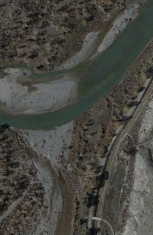
3 no damage to the LeClair canal bank will occur. Is there any analysis as to how much water can be expected to come down the North channel during flood events? LeClair also has concerns about water backing up enough to overtop the diversion structure (at -600 station) headwall at elevation Presently, the dam/plug is not yet complete and part of the south channel is still being used even with 450 cfs in the river. Apparently the West end of the dam was removed or breached concurrently with the end of the construction activity (December 2016) to relieve rising water levels upstream of the dam/plug. See dam breach in center of photo below. Once the breach is repaired, there are grave concerns as what extent flooding in the North channel will occur. While an exhaustive asbuilt survey of the completed channel has not been made available, evidence presented by this one surveyed cross section (956 section) should at least bring some attention to LeClair s concerns for the bigger picture. I would be available to answer any questions you might have on what we have provided. Terry Zenk, P.E. Apex Surveying, Inc. Page 3
4
5
KKR S. 6 th St. to I-94 Bridge Project Location. Expanded Floodplains
 Kinnickinnic River Watercourse Rehabilitation Early Out Project Achieving Multiple Design Objectives Thomas R. Sear, PE, CFM Short Elliott Hendrickson Patrick C. Elliott, PE Milwaukee Metropolitan Sewerage
Town of Westlake Construction Plans Review Checklist
 CONSTRUCTION PLANS CONTENTS All Drawings 24 x 36 Cover Sheet Final Plat Site Plan Demolition Plan Utility Plan Drainage Area Map and Calculations Paving Plan & Profile Sheets Storm Drain Plan & Profile
The Basics. HECRAS Basis Input. Geometry Data - the basics. Geometry Data. Flow Data. Perform Hydraulic Computations. Viewing the Output
 The Basics HECRAS Basis Input Geometry Data. Flow Data. Perform Hydraulic Computations by G. Parodi WRS ITC The Netherlands Viewing the Output ITC Faculty of Geo-Information Science and Earth Observation
RE: Engineered Riffle Concepts for Sodom Dam Removal Grade Control Elements
 November 19, 2009 Ms. Melissa Jundt NOAA Fisheries Hydropower Division 1201 NE Lloyd Boulevard, Suite 1100 Portland, Oregon 97232 RE: Engineered Riffle Concepts for Sodom Dam Removal Grade Control Elements
URBAN DRAINAGE AND FLOOD CONTROL DISTRICT
 URBAN DRAINAGE AND FLOOD CONTROL DISTRICT Digital Flood Hazard Area Delineation (DFHAD) Guidelines July 2009 Prepared by 720 South Colorado Boulevard Suite 410 S Denver, Colorado 80246 phone (303) 757-3655
Floodplain Modeling 101. Presentation Goals
 Floodplain Modeling 101 Presenter: Joseph L. Miller, P.E., CFM 2016 INAFSM Conference Presentation Goals Introduction to Indiana s and FEMA s floodplain modeling technical requirements for riverine modeling
APPENDIX I FLOODPLAIN ANALYSIS
 APPENDIX I FLOODPLAIN ANALYSIS TECHNICAL MEMORANDUM Date: June 11, 2014 To: Bibiana Alvarez and Ryan Lee Sawyer, Analytical Environmental Services From: Melanie Carr, MS, PE, Tarick Abu- Aly, MS, PE, Rafael
50.24 Type, Size and Location Plans for Culverts, Bridges and Culvert Bridges
 50.24 Culverts, Bridges and Culvert Bridges Type, Size and Location (T, S & L) Plans shall be required for all Bridges, Culvert Bridges and Culverts of eight-foot (8') clear span or greater as follows:
PART XIII: HYDRAULIC/ HYDROLOGY SURVEYS
 PART XIII: HYDRAULIC/ HYDROLOGY SURVEYS 13.1 Purpose and Scope Hydraulic surveys are required for flow analysis to determine bridge and culvert design characteristics. A hydraulic survey is usually but
Appendix N: Data Capture Guidelines Summary of Changes
 Appendix N: Data Capture Guidelines Summary of Changes The following Summary of Changes details revisions of Appendix N subsequent to the initial publication of the Draft Appendix N in April 2004. These
Ecological Restoration Drafting & Design Guidelines
 Ecological Restoration Drafting & Design Guidelines Version 2.0 July 2017 Philadelphia Water Ecological Restoration Drafting & Design Guidelines Table of Contents 1.0 INTRODUCTION...2 2.0 GENERAL PLAN
Anne Arundel County Dept. of Inspections and Permits Storm Drain Checklist
 Project Name Project Number Engineer Plans are to be designed based on the standards set forth in the Anne Arundel County Design Manual Standards and Specifications, and all other manuals as stipulated
APPENDIX E CIVIL DESIGN (QUANTITY CALCULATION)
") APPENDIX E CIVIL DESIGN (QUANTITY CALCULATION) LOWER CACHE RIVER 1135 CIVIL DESIGN CALCULATIONS R2200, R90, & FILTER MATERIAL VOLUME CALCULATIONS FOR WEIR STRUCTURES EMBEDDED RIPRAP THICKNESS 4' 6'
APPENDIX E CIVIL DESIGN (QUANTITY CALCULATION) LOWER CACHE RIVER 1135 CIVIL DESIGN CALCULATIONS R2200, R90, & FILTER MATERIAL VOLUME CALCULATIONS FOR WEIR STRUCTURES EMBEDDED RIPRAP THICKNESS 4' 6'
B422 - PRECAST REINFORCED CONCRETE BOX CULVERTS AND BOX SEWERS - OPSS 422
 B422 - PRECAST REINFORCED CONCRETE BOX CULVERTS AND BOX SEWERS - OPSS 422 422.1 GENERAL The work under these tender items consists of the fabrication and installation in open cut of precast reinforced
DEVELOPMENT PLAN CHECKLIST
 Project Identification Information: DEVELOPMENT PLAN CHECKLIST 1.0 GENERAL 1.1 Additional information as required by specific Land Use 1.2 All sheets to include sheet number ( of ) 1.3 Seal and signature
City of Massillon Site Plan Checklist
 City of Massillon Site Plan Checklist The following information MUST be included with all Site Plans submitted for review and processing in order to constitute a complete Site Plan Package. Incomplete
Field Observations and One-Dimensional Flow Modeling of Summit Creek in Mack Park, Smithfield, Utah
 Sediment Transport Workshop, Utah State University, 1 August 2017 Field Observations and One-Dimensional Flow Modeling of Summit Creek in Mack Park, Smithfield, Utah I. Goals for learning and discussion:
Sewer Line Extension Permit Design Checklist
 CHECKLIST C1 Revised 4/7/2017 Sewer Line Extension Permit Design Checklist DISCLAIMER - This checklist is provided to Consulting Engineers for the express purpose of assisting them in compiling sewer line
Iowa Bridge Sensor Demonstration Project Phase I and Phase II Executive Summary Report. Floodplain Management Services Silver Jackets Pilot Study
 Iowa Bridge Sensor Demonstration Project Phase I and Phase II Executive Summary Report Floodplain Management Services Silver Jackets Pilot Study Final Report AUGUST 2016 Iowa Bridge Sensor Demonstration
Compensatory Mitigation Monitoring Report Aquatic Habitat Improvement City of Montrose Whitewater Park, Montrose County, Colorado March 6, 2014
 Compensatory Mitigation Monitoring Report Aquatic Habitat Improvement City of Montrose Whitewater Park, Montrose County, Colorado March 6, 2014 i. Project Overview 1. USACE # # SPK 2013 00851 2. Permittee:
Authorized Agent: City of Manassas Check List Attached: Contact: Address: Phone Number: Fax Number: Developer s Name: Phone Number:
 CITY OF MANASSAS DEPARTMENT OF COMMUNITY DEVELOPMENT DEVELOPMENT SERVICES DIVISION 9027 Center Street Room 201 Manassas, Virginia, 20110 Phone: 703-257-8278 Fax: 703-257-5831 Application Date: APPLICANT
B-PERMIT PLAN CHECK MANUAL
 B-PERMIT PLAN CHECK MANUAL 5. SEWER PLANS Sewer Plans are usually submitted in conjunction with Street Plans to meet the requirements of conditions imposed on a Planning or Zoning action. In some cases
CE 365K Exercise 2: HEC-RAS Modeling Spring 2014 Hydraulic Engineering Design
 CE 365K Exercise 2: HEC-RAS Modeling Spring 2014 Hydraulic Engineering Design This exercise was prepared by Fernando R. Salas and David R. Maidment Introduction In this exercise, we will learn how to setup
Flood Hazard Area Delineation Guidelines MOSER & ASSOCIATES ENGINEERING ICON ENGINEERING URBAN DRAINAGE AND FLOOD CONTROL DISTRICT
 Flood Hazard Area Delineation Guidelines MOSER & ASSOCIATES ENGINEERING ICON ENGINEERING URBAN DRAINAGE AND FLOOD CONTROL DISTRICT Flood Hazard Area Delineation (FHAD) Guidelines Contents Section Page
Attn: Emil Pierson, Community Development Director
 November 27, 2018 City of Centralia 118 Maple Street Centralia, A 98531 Attn: Emil Pierson, Community Development Director Re: Floodplain Cut/Fill Report Dear Emil, HBH Consulting Engineers, Inc (HBH)
APPLICATION FOR SITE PREPARATION PERMIT
 Engineering Division 550 Landa Street New Braunfels, Texas 78130 (830) 221-4020 1. Subdivision/Plat Name: Location Description/ Nearest Intersection: Acreage: APPLICATION FOR SITE PREPARATION PERMIT No.
BRASELTON WATER AND WASTEWATER DEPARTMENT CONSTRUCTION PLAN REVIEW CHECKLIST May 2006
 Project Name: BRASELTON WATER AND WASTEWATER DEPARTMENT CONSTRUCTION PLAN REVIEW CHECKLIST May 2006 Phase: Unit: # Lots: Development Type (residential, commercial, industrial, etc.) Braselton Project No.
B.2 MAJOR SUBDIVISION PRELIMINARY PLAN CHECKLIST
 B.2 MAJOR SUBDIVISION PRELIMINARY PLAN CHECKLIST YES* GENERAL SUBMISSION ITEMS Does the submission include: 1. Thirteen (13) copies of completed Application Form? 2. Thirteen (13) copies of the Preliminary
CITY OF APACHE JUNCTION DEVELOPMENT SERVICES CIVIL ENGINEERING PLAN REVIEW CHECKLIST PROJECT: LOCATION:
 CITY OF APACHE JUNCTION DEVELOPMENT SERVICES CIVIL ENGINEERING PLAN REVIEW CHECKLIST PROJECT: LOCATION: LOG NO.: LEGEND REVIEW REVIEWED BY DATE / - Requirement satisfied 1 O Requirement not satisfied 2?
MAJOR GRADING PLAN CHECKLIST
 MAJOR GRADING PLAN CHECKLIST PUBLIC WORKS DEPARTMENT / ENGINEERING DIVISION 8130 Allison Avenue, La Mesa, CA 91942 Phone: (619) 667-1166 Fax: (619) 667-1380 Grading plans shall address both rough grading
Digital Flood Hazard Area Delineation (DFHAD) Guidelines
 Guidelines") Digital Flood Hazard Area Delineation (DFHAD) Guidelines Contents Section Page Acronyms and Abbreviations Abbreviations and Acronyms... iii Revise Descriptions... iv 1.0 Introduction and Purpose... 1 1.1
Digital Flood Hazard Area Delineation (DFHAD) Guidelines Contents Section Page Acronyms and Abbreviations Abbreviations and Acronyms... iii Revise Descriptions... iv 1.0 Introduction and Purpose... 1 1.1
This Land Surveying course has been developed by. Failure & Damage Analysis, Inc.
 This Land Surveying course has been developed by Failure & Damage Analysis, Inc. www.discountpdh.com www.pepdh.com Bridge Surveying SURVEYS Bridge surveying is necessary to locate a site, obtain information
Surveying & Measurement. Detail Survey Topographic Surveying
 Surveying & Measurement Detail Survey Topographic Surveying Introduction Mapping surveys are made to determine the relief of the earth s surface and locate critical points on it. to determine the locations
CITY OF TUMWATER 555 ISRAEL RD. SW, TUMWATER, WA (360)
") CITY OF TUMWATER 555 ISRAEL RD. SW, TUMWATER, WA 98501 (360) 754-4180 Email: cdd@ci.tumwater.wa.us WATER-SEWER-STREET-STORM (IN CITY) Submittal Checklist TUM - RCVD BY DATE STAMP APPLICANT INFORMATION
CITY OF TUMWATER 555 ISRAEL RD. SW, TUMWATER, WA 98501 (360) 754-4180 Email: cdd@ci.tumwater.wa.us WATER-SEWER-STREET-STORM (IN CITY) Submittal Checklist TUM - RCVD BY DATE STAMP APPLICANT INFORMATION
For crossing under a railroad, contact the specific railroad company's engineering department.
 PAGE 330524-1 SECTION 330524 SPECIFIER: This section is for the underground installation of piping by directional drilling. When specifying this method of piping installation, care must be taken to ensure
TYPICAL SECTIONS TYPICAL NO. 1 (MAINLINE) STA TO STA STA TO STA ROUNDING DETAIL TYPICAL NO.
 STA TO STA STA TO STA ROUNDING DETAIL TYPICAL NO.") FILL SECTION TYPICAL NO. 1 (MAINLINE) STA. 2434. TO STA. 244035.16 STA. 244396.83 TO STA. 2449. CUT SECTION ROUNDING DETAIL FILL SECTION TYPICAL NO. 3 (DETOUR) CUT SECTION STA. 242849.86 TO STA. 2453.88
FILL SECTION TYPICAL NO. 1 (MAINLINE) STA. 2434. TO STA. 244035.16 STA. 244396.83 TO STA. 2449. CUT SECTION ROUNDING DETAIL FILL SECTION TYPICAL NO. 3 (DETOUR) CUT SECTION STA. 242849.86 TO STA. 2453.88
SECTION 100 PRELIMINARY CONSIDERATIONS & INSTRUCTIONS
 SECTION 100 PRELIMINARY CONSIDERATIONS & INSTRUCTIONS 101 General 102 Submittal Requirements A. Initial Submittal B. Second Submittal 103 Plan Requirements A. Subdivisions B. Site Plans 104 Approval of
UTILITY AND STREET CONSTRUCTION PLAN REQUIREMENTS SECTION 1
 UTILITY AND STREET CONSTRUCTION PLAN REQUIREMENTS SECTION 1 ENGINEERING STANDARDS FOR UTILITY AND STREET CONSTRUCTION PLANS MARCH 2014 CONSTRUCTION PLAN SHEET FORMAT REQUIREMENTS REPRODUCIBLE MYLAR 1.
GENERAL DEVELOPMENT APPLICATIONS. General Submission Requirements
 COMPLETE APPLICATION CHECKLIST Jan 2016 The following checklist has been compiled to assist the applicant in preparing their application for approval pursuant to Ontario Regulation 162/06. This checklist
Loy Gulch, Paint Pony, East Fork Paint Pony LOMR
 Loy Gulch, Paint Pony, East Fork Paint Pony LOMR Woodland Park, CO Prepared by: Michael Baker International 165 S. Union Blvd, Suite 200 Lakewood, CO 80226 TABLE OF CONTENTS I. INTRODUCTION... 2 1.1 Purpose...
Technical Memorandum ECO-7
 To: Woody Frossard, TRWD From: Bob Brashear, CDM This document is released for the purpose of interim review under the authority of Robert Brashear, P.E., TX license 80771 on 21-Mar-2005. It is not to
CHAPTER 11 SURVEY CADD
 CHAPTER 11 SURVEY CADD Chapter Contents Sec. 11.01 Sec. 11.02 Sec. 11.03 Sec. 11.04 Sec. 11.05 Sec. 11.06 Sec. 11.07 Sec. 11.08 Sec. 11.09 Sec. 11.10 General Description of Survey File Contents of Survey
Hillside & Foothills Development Application
 Hillside & Foothills Development Application This box for office use only File #: Cross Referenced File(s): Fee: Zone(s): Are Pre-Application materials attached? Yes No This application is a request to
SUMMIT COUNTY PLANNING AND ENGINEERING DEPARTMENT
 SUMMIT COUNTY PLANNING AND ENGINEERING DEPARTMENT SINGLE-FAMILY SITE PLAN INFORMATION PACKET GENERAL INFORMATION This information packet explains how your application for a single-family site plan will
CITY OF BEVERLY HILLS Department of Public Works and Transportation Civil Engineering Division STORM DRAIN IMPROVEMENT PLAN REVIEW CHECKLIST
 CITY OF BEVERLY HILLS Department of Public Works and Transportation Civil ing Division STORM DRAIN IMPROVEMENT PLAN REVIEW CHECKLIST The following checklist consists of the minimum requirements for preparation
Survey Data and TOPO Checklist
 Checklists Survey Data and TOPO Preliminary Plan Field Review Plans o Field Review Erosion Control Right-of-Way and Utility Meeting Plans Final Plan Field Review Plans Methods of Plan Markups Plan-in-Hand
City of Beaumont. Public Works Engineering. Street Improvement Plan Checklist REV 4/18/16
 City of Beaumont Public Works Engineering Project Name: TR: Project No.: Date: Street Improvement Plan Checklist Chk A. All Sheets 1. 24" x 36" 2. Signed by the engineer-of-work 3. Marked with the contact
Hydraulics and Floodplain Modeling Managing HEC-RAS Cross Sections
 v. 9.1 WMS 9.1 Tutorial Hydraulics and Floodplain Modeling Managing HEC-RAS Cross Sections Modify cross sections in an HEC-RAS model to use surveyed cross section data Objectives Build a basic HEC-RAS
APPENDIX E - FLOODPLAIN INFORMATION
 CITY OF WOODLAND PARK STORMWATER MASTER PLAN - Floodplain Information APPENDIX E - FLOODPLAIN INFORMATION E1 - Floodplain Information TABLE OF CONTENTS I. INTRODUCTION... 2 Loy Gulch, Paint Pony, East
Traffic and Roadway Improvements - Rte 123 (Belmont Street) Brockton, MA Client: BETA Group, Inc.
 Brockton, MA Client: BETA Group, Inc.") HIGHWAY PROJECT EXPERIENCE Traffic and Roadway Improvements - Rte 123 (Belmont Street) Brockton, MA Client: BETA Group, Inc. Alpha provided survey services to prepare a base plan of an approximately 2900
HIGHWAY PROJECT EXPERIENCE Traffic and Roadway Improvements - Rte 123 (Belmont Street) Brockton, MA Client: BETA Group, Inc. Alpha provided survey services to prepare a base plan of an approximately 2900
This is a digital document from the collections of the Wyoming Water Resources Data System (WRDS) Library.
 Library.") This is a digital document from the collections of the Wyoming Water Resources Data System (WRDS) Library. For additional information about this document and the document conversion process, please contact
This is a digital document from the collections of the Wyoming Water Resources Data System (WRDS) Library. For additional information about this document and the document conversion process, please contact
September 21, Mannik Smith Group 1771 North Dixie Highway Monroe, Michigan RE: LA Fitness City File No.: CVLP
 CITY OF ANN ARBOR, MICHIGAN Public Services Area / Engineering 301 E. Huron Street, P.O. Box 8647 Ann Arbor, Michigan 48107 Phone (734) 794-6410 Fax (734) 994-1744 Web: www.a2gov.org Printed on recycled
STATE UNIVERSITY CONSTRUCTION FUND
 DIRECTIVE 1C-12 Issue date: August 2012 1. General SURVEY, MAPPING AND UTILITY LOCATING This Directive has been developed as a general guide for the survey and mapping effort required for Fund projects.
A. Dewatering observation wells are part of dewatering allowance.
 SECTION 312319 - DEWATERING PART 1 - GENERAL 1.1 RELATED DOCUMENTS A. Drawings and general provisions of the Contract, including General and Supplementary Conditions and Division 01 Specification Sections,
City of Colleyville Community Development Department. Site/Landscape Plan Application Packet
 City of Colleyville Community Development Department Site/Landscape Plan Application Packet 1 Development Application Fees City of Colleyville 100 Main Street Colleyville TX 76034 817.503.1050 Zoning Zoning
Presented By: Todd Ward Project Manager
 Presented By: Todd Ward Project Manager Mailing Address All submittals for LOMRs and CLOMRs Harris County should be directed to Harris County Flood Control District. Submittals can be mailed or hand-delivered
SPECIAL PUBLIC NOTICE
 SPECIAL PUBLIC NOTICE Draft Map and Drawing Standards for the South Pacific Division Regulatory Program August 6, 2012 Corps contacts: Sacramento District: Michael Finan (916) 557-5324 (Michael.C.Finan@usace.army.mil)
SECTION DEWATERING PART 1 - GENERAL 1.1 RELATED DOCUMENTS
 SECTION 312319 - DEWATERING PART 1 - GENERAL 1.1 RELATED DOCUMENTS A. Drawings and general provisions of the Contract, including General and Supplementary Conditions and Division 01 Specification Sections,
Date Requested, 200_ Work Order No. Funding source Name of project Project limits: Purpose of the project
 Bureau of Engineering SURVEY DIVISION REQUEST FOR TOPOGRAPHIC SURVEY Date Requested, 200_ Work Order No. Funding source Name of project Project limits: Purpose of the project Caltrans involvement (must
CITY OF DANA POINT DEVELOPMENT REVIEW
 Section I EARTHWORK CITY OF DANA POINT DEVELOPMENT REVIEW COST ESTIMATE UNIT PRICE LIST May 2002 Page 1 of 12 Section I EARTHWORK TABLE OF CONTENTS SECTION AND TOPICS...PAGE INTRODUCTION... i I EARTHWORK...
SITE PLAN, SUBDIVISION & EXTERIOR DESIGN REVIEW PROCESS
 INCORPORATED VILLAGE OF ROCKVILLE CENTRE BUILDING DEPARTMENT SITE PLAN, SUBDIVISION & EXTERIOR DESIGN REVIEW PROCESS Presubmission - Prior to a formal submission, the applicant should meet in person with
ACWWA DRAWING SUBMITTAL INFORMATION - UTILITY DRAWING REQUIREMENTS
 ACWWA DRAWING SUBMITTAL INFORMATION - UTILITY DRAWING REQUIREMENTS Detailed construction drawings for system extensions shall be prepared for approval with a submittal to the Authority. All construction
CHAPTER 2C - PRELIMINARY DESIGN. General... 2C-1. Review of Work Load... 2C-2 Establishing Priorities... 2C-2
 SECTION 2C - 1 - PROJECT REVIEW CHAPTER 2C - PRELIMINARY DESIGN General... 2C-1 SECTION 2C - 2 - COORDINATING TIME SCHEDULES Review of Work Load... 2C-2 Establishing Priorities... 2C-2 SECTION 2C 3 - REVIEW
List of Figures. List of Forms
 City of Columbia Engineering Regulations PART 1: SUBMISSION OF PLANS Table of Contents Paragraph Description Page No. 1.1 General 1-1 1.2 Engineer s Report 1-1 1.3 Plans 1-3 1.4 Revisions to Approved Plan
Rebman Creek Evaluation of In-Stream Rehabilitation Structures
 Rebman Creek Evaluation of In-Stream Rehabilitation Structures Draft Report Prepared for: Weldwood of Canada Ltd. Quesnel, BC by: G3 Consulting Ltd. 4508 Beedie Street Burnaby, BC V5J 5L2 December 2000
Hydraulics and Floodplain Modeling Managing HEC-RAS Cross Sections
 WMS 10.1 Tutorial Hydraulics and Floodplain Modeling Managing HEC-RAS Cross Sections Modify cross sections in an HEC-RAS model to use surveyed cross section data v. 10.1 Objectives Build a basic HEC-RAS
UPPER MISSISSIPPI RIVER RESTORATION LAKE ODESSA HABITAT REHABILITATION AND ENHANCEMENT PROJECT OPERATION AND MAINTENANCE MANUAL APPENDIX F
 UPPER MISSISSIPPI RIVER RESTORATION LAKE ODESSA HABITAT REHABILITATION AND ENHANCEMENT PROJECT OPERATION AND MAINTENANCE MANUAL APPENDIX F PROJECT PHOTOGRAPHS Table of Photographs Photograph 1: Lake Odessa
Digital Letter of Map Change (DLOMC) Guidelines May 2010
 Guidelines May 2010") Digital Letter of Map Change (DLOMC) Guidelines May 2010 Prepared for: Urban Drainage and Flood Control District 2450 West 26th Avenue, Suite 156B Denver, CO 80211 Prepared by: 8100 South Akron Street,
Digital Letter of Map Change (DLOMC) Guidelines May 2010 Prepared for: Urban Drainage and Flood Control District 2450 West 26th Avenue, Suite 156B Denver, CO 80211 Prepared by: 8100 South Akron Street,
Chapter 13 Plan Submittals
 Chapter 13 Plan Submittals U30013.DOC 02/01/07 Chapter 13 Plan Submittals Section Topic Page 13.1 General 13.1 13.2 Subdivision Plans 13.1 13.3 Capital Improvement Project Plans 13.12 U30013.DOC 02/01/07
SECTION 3 IMPROVEMENT PLAN REQUIREMENTS
 SECTION 3 IMPROVEMENT PLAN REQUIREMENTS CONTENTS Page 3-1 Digital Submittals 3-2 3-2 Paper Size and Scale 3-2 3-3 Drafting Standard 3-2 3-4 Title Sheet 3-2 3-5 Title Block 3-3 3-6 Drainage, Sewer, Water,
SECTION DEWATERING TANKAGE PART 1 - GENERAL 1.1 RELATED DOCUMENTS
 SECTION 31 23 19 - DEWATERING TANKAGE PART 1 - GENERAL 1.1 RELATED DOCUMENTS A. Drawings and general provisions of the Contract, including General and Supplementary Conditions and Division 1 Specification
Example Application C H A P T E R 4. Contents
 C H A P T E R 4 Example Application This chapter provides an example application of how to perform steady flow water surface profile calculations with HEC-RAS. The user is taken through a step-by-step
The Benefits and Appropriate Use of Base Flood Approximate Shapefiles to Calculate Zone A Base Flood Elevations. Jeremy Kirkendall, CFM June 12, 2013
 The Benefits and Appropriate Use of Base Flood Approximate Shapefiles to Calculate Zone A Base Flood Elevations Jeremy Kirkendall, CFM June 12, 2013 Federal Emergency Management Agency (FEMA) Flood Insurance
MULTIPLE-FAMILY DESIGN REVIEW SUBMITTAL CHECKLIST
 MULTIPLE-FAMILY DESIGN REVIEW SUBMITTAL CHECKLIST This application lists the content and format of the submittal requirements to initiate the Design Review process. An incomplete application will not be
Essential Skills: Reading and Interpreting Maps and Plans
 Essential Skills: Reading and Interpreting Maps and Plans Prepared for: NEW YORK STATE PLANNING FEDERATION April 14, 2015 Prepared by: BME ASSOCIATES Peter G. Vars, P.E. Stages of Plan Review Concept /
Legal Description & Site Plan Requirements and Layouts
 Legal Description & Site Plan Requirements and Layouts Plot Plan * A plot plan shows the location of a house from an aerial view. * The site plan, also known as a plot or lot plan includes: 1. Site plan
Section E NSPS MODEL STANDARDS FOR TOPOGRAPHIC SURVEYS Approved 3/12/02
 Section E NSPS MODEL STANDARDS FOR TOPOGRAPHIC SURVEYS Approved 3/12/02 1. INTRODUCTION This standard is written to provide the professional surveyor (Surveyor) and the client with a guideline for producing
GEO-SLOPE International Ltd, Calgary, Alberta, Canada Relief Well Spacing
 1 Introduction Relief Well Spacing Relief wells are commonly installed on the downstream side of an earth dam to control the seepage and pore-pressures (e.g. levee; Figure 1). A key design requirement
RESIDENTIAL DEMOLITION PERMIT APPLICANT CHECKLIST
 RESIDENTIAL DEMOLITION PERMIT APPLICANT CHECKLIST The purpose of this form is to inform applicants of: 1) the requirements for building permits and stormwater permits for residential demolition projects;
Bestall Collaborative Limited Planning Environment Construction Management Development
 November 18, 2017 Bestall Collaborative Limited Lori Hight, AICP, Senior Planner City Development Department City of Thornton City Hall 9500 Civic Center Drive Thornton, Colorado 80229-4326 RE: River Valley
3 Table of Contents. Introduction. Installing and Activating... 8 Getting Updates Basic Working Procedures
 User's Guide 3 Table of Contents 1. Introduction 5 1.1 Installing and Activating... 8 1.2 Getting Updates... 9 2. 11 2.1 What To Do First... 13 2.2 Starting a New Project... 14 2.3 Setting Up Your Model...
King And Queen County, VA P.O. Box 177 King and Queen Courthouse, VA (804) (804) (fax)
 (804) (fax)") King And Queen County, VA P.O. Box 177 King and Queen Courthouse, VA 23085 (804) 785-5975 (804) 785-5999 (fax) Shoreline Erosion Project Water Quality Impact Assessment (WQIA) & Wetland Board Permit Submittal
King And Queen County, VA P.O. Box 177 King and Queen Courthouse, VA 23085 (804) 785-5975 (804) 785-5999 (fax) Shoreline Erosion Project Water Quality Impact Assessment (WQIA) & Wetland Board Permit Submittal
PRE-LAB for: Introduction to Aerial Photographs and Topographic maps (Ch. 3)
") GEOLOGY 306 Laboratory Instructor: TERRY J. BOROUGHS NAME: PRE-LAB for: Introduction to Aerial Photographs and Topographic maps (Ch. 3) For this assignment you will require: a calculator and metric ruler.
GEOLOGY 306 Laboratory Instructor: TERRY J. BOROUGHS NAME: PRE-LAB for: Introduction to Aerial Photographs and Topographic maps (Ch. 3) For this assignment you will require: a calculator and metric ruler.
Porter County Plan Commission
 Plan Type: Development Plan Administrative DRC PC Primary Plan Administrative DRC PC Secondary Plat/Replat Administrative DRC PC PUD Conceptual Detailed Final Project Information Project Name: Developer
SECTION SITE SURVEYS
 SECTION 02 21 13 SITE SURVEYS SPEC WRITER NOTE: 1. Delete text between // // not applicable to project. Edit remaining text to suit project. 2. Use this section to specify survey required before design
Oil-Water Separator Design Checklist
 CHECKLIST C3 Revised 5/2/2016 Oil-Water Separator Design Checklist DISCLAIMER - This checklist is provided to Consulting Engineers for the express purpose of assisting them in compiling private oil-water
Plan Preparation Checklist
 Appendix D Plan Preparation Checklist It is the responsibility of the Designer to complete and submit this checklist along with all required drawings for OUC (EFP) Review. All drawings submitted for OUC
Discovery Report Appendix L Dams and Floodplain Structures Lake Ontario St. Lawrence Watershed HUC
 Discovery Report Appendix L Dams and Floodplain Structures Lake Ontario St. Lawrence Watershed HUC 04150309 July 2016 Federal Emergency Management Agency Department of Homeland Security 26 Federal Plaza
The several methods for making linear measurements are quite simple and straightforward. They are described below:
 INTRODUCTION TO LINEAR MEASUREMENTS Many pay items are measured on the basis of linear measurements - items such as guardrail, pipe culvert, curb and gutter, fencing, etc. These measurements usually are
CITY OF BEVERLY HILLS Department of Public Works and Transportation Civil Engineering Division SANITARY SEWER IMPROVEMENT PLAN REVIEW CHECKLIST
 CITY OF BEVERLY HILLS Department of Public Works and Transportation Civil ing Division SANITARY SEWER IMPROVEMENT PLAN REVIEW CHECKLIST The following checklist consists of the minimum requirements for
Bentleyuser.dk Årsmøde 2010 Nordic Civil 2010
 Bentleyuser.dk Årsmøde 2010 Nordic Civil 2010 8.-10. November 2010, Munkebjerg Hotel, Vejle Workshop - X9 Resurfacing and Overlay Tools InRoads V8i Presenter: Joe Waxmonsky, P.E., Bentley Systems USA Bentley
1.1 GENERAL RECORD DRAWING REQUIREMENTS
 Page 1 of 5 VILLAGE OF ROMEOVILLE RECORD DRAWINGS CHECKLIST PART I GENERAL Record drawings are required to provide a means of schematic verification that the intent of the approved engineering design has
CONCEPT REVIEW GUIDELINES
 Department of Planning & Community Development @ Jefferson Station 1526 E. Forrest Avenue Suite 100 East Point, GA 30344 404.270.7212 (Phone) 404.765.2784 (Fax) www.eastpointcity.org CONCEPT REVIEW GUIDELINES
Water Surface Profiles
 United States Department of Agriculture Natural Resources Conservation Service Hydrology Computer Program for Water Issued October 1993 Revision March 2005 The United States Department of Agriculture (USDA)
Oakland County Michigan Register of Deeds Plat Engineering, GIS, & Remonumentation Dept. Ph: (248) Fax (248)
 Fax (248)") Oakland County Michigan Register of Deeds Plat Engineering, GIS, & Remonumentation Dept. Ph: (248)-858-1447 Fax (248)-858-7466 Requirements Needed for Final Condominium Approval General Requirements. 1
Oakland County Michigan Register of Deeds Plat Engineering, GIS, & Remonumentation Dept. Ph: (248)-858-1447 Fax (248)-858-7466 Requirements Needed for Final Condominium Approval General Requirements. 1
MINOR SUBDIVISION. [ ] [ ] [ ] [ ] B. Dimensions, bearings and curve data for all property lines and easements.
![MINOR SUBDIVISION. [ ] [ ] [ ] [ ] B. Dimensions, bearings and curve data for all property lines and easements.](/thumbs/90/102241643.jpg "MINOR SUBDIVISION. [ ] [ ] [ ] [ ] B. Dimensions, bearings and curve data for all property lines and easements.") MINOR SUBDIVISION 190-69. Minor subdivisions. In addition to the requirements indicated in 190-67 (SEE BELOW), the information below shall be shown on the plans for all minor subdivision applications.
MINOR SUBDIVISION 190-69. Minor subdivisions. In addition to the requirements indicated in 190-67 (SEE BELOW), the information below shall be shown on the plans for all minor subdivision applications.
Zoning District: R-1, R-2, and R-4 Applicant: Exeter Rose Farm, LLC, 953 Islington Street #23D Portsmouth, NH 03801
 2220.00, Town Planner Town Planning Office, Town of Exeter 10 Front Street Exeter, NH 03833 Re: Exeter Rose Farm Subdivision Design Review Engineering Services Exeter, New Hampshire Site Information: Tax
GCG ASSOCIATES, INC. February 8, Mr. Nathaniel Strosberg, Town Planner 101 Main Street Town of Ashland Ashland, MA 01721
 GCG ASSOCIATES, INC. CIVIL ENGINEERING AND LAND SURVEYING 84 Main Street Wilmington, Massachusetts 01887 Phone: (978) 657-9714 Fax: (978) 657-7915 February 8, 2016 Mr. Nathaniel Strosberg, Town Planner
580 - NOISE BARRIERS OPSS 580 INDEX
 580 - OPSS 580 INDEX 580.1 GENERAL 580.1.1 Noise Barrier Design Elements 580.1.1.1 Wind-Load Designs 580.1.1.2 Sound-Absorptive Barriers 580.1.1.3 Noise Barrier Colour, Pattern and Texture 580.1.2 Grading
Town of Apex, North Carolina
 POND DRAINAGE PLAN APPLICATION Town of Apex, North Carolina POND DRAINAGE PLAN APPLICATION: Applications are due by 12:00 pm on the first business day of each month. Please see the Minor Site Plan Schedule