Surveying & Measurement. Detail Survey Topographic Surveying
|
|
|
- Marshall Carroll
- 5 years ago
- Views:
Transcription

1 Surveying & Measurement Detail Survey Topographic Surveying
2 Introduction Mapping surveys are made to determine the relief of the earth s surface and locate critical points on it. to determine the locations of natural, and cultural features on the earth s surface, and to define the configuration of that surface.
3 The Surface Features The features that are included on the map are determined by the purpose of the map. Natural features on the maps include vegetation, rivers, lakes, oceans, etc.
4 The Surface Features Cultural features on the maps are the products of people, and include roads, railroads, buildings, bridges, canals, boundary lines, etc.
5 Type of Maps Planimetric; include natural and cultural features in the plan view only, and Topographic; include planimetric features and show the configuration of the earth s surface.
6 Map Scale The ratio of the length of an object or feature on a map to the true length of the object or feature. Map scales are given in three ways: by ratio or representative fraction, such as 1:2000 or 1/2000 (A scale of 1:2000 means that one unit on the map equals 2000 of the same units on the ground). by an equivalence, for example 1 cm = 200 m. graphically using either a bar scale or labelled grid lines spaced.
7 Contours A contour is a line connecting points of equal elevations. Contours cannot be seen in nature. On maps, contours represent the planimetric locations of the traces of level surfaces for different elevations. The elevation difference between the adjacent contours is called the contour interval. The contour interval depends on a map s purpose and scale.
8 Contours (a) Plan view of contour lines (b) Profile view (c) Profile view
9 Characteristics of Contours Contour lines are continuous. Contour lines are relatively parallel unless one of two conditions exists. A series of V-shape indicates a valley and the V s point to higher elevation. A series U shape indicates a ridge. The U shapes will point to lower elevation. Evenly spaced lines indicate an area of uniform slope.
10 Characteristics of Contours A series of closed contours with increasing elevation indicates a hill and a series of closed contours with decreasing elevation indicates a depression. Closed contours may be identified with a +, hill, or -, depression. Closed contours may include hachure marks. Hachures are short lines perpendicular to the contour line. They point to lower elevation.
11 Characteristics of Contours The distance between contour lines indicates the steepness of the slope. The greater the distance between two contours the less the slope. The opposite is also true. Contours are perpendicular to the maximum slope. A different type of line should be used for contours of major elevations. For example at 100, 50 and 10 foot intervals. Common practice is to identify the major elevations lines, or every fifth line, with a bolder, wider, line.
12 Characteristics of Contours
13 Characteristics of Contours
14 Contours are Continuous Some contour lines may close within the map, but others will not. In this case, they will start at a boundary line and end at a boundary line. Contours must either close or extend from boundary to boundary.
15 Contour Lines are Parallel Two exceptions: They will meet at a vertical cliff They will overlap at a cave or overhang. When contour lines overlap, the lower elevation contour should be dashed for the duration of the overlap.

16 Valleys and Higher Elevation A series of V-shapes indicates a valley and the V s point to higher elevation.

17 U Shapes and Ridge A series of U shapes indicates a ridge. The U shapes will point to lower elevation.
18 Contour Spacing Evenly spaced contours indicate an area of uniform slope. Unevenly spaced contours indicates an area with variable slope.
19 Hills and Depressions A series of closed contours with increasing elevation indicates a hill. Hills may be identified with a + with the elevations and depressions may be identified with a -.
20 Hills and Depressions A series of closed contours with decreasing elevation indicates a depression.
21 Hachures Hachures are short lines which are perpendicular to the contour line. Used to indicate a hill or a depression.
22 Contour Spacing Contours spaced close together indicate a steep slope. Contours spaced wider apart indicate less slope.
23 Contours are perpendicular to the maximum slope.

24 Different types of lines should be used for contours of major elevations. Common practice is to identify the major elevations lines, or every fifth line, with a bolder, wider, line.
25 Data Acquisition When collecting topo data there are two important issues: Ensuring sufficient data is collected to define the object. Ensuring two types of information is gathered for each station: Location Elevation
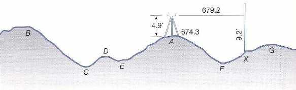
26 Direct Method In this method, the contour lines are physically followed on the ground using a total station. After the instrument set up, the HI is established, and the telescope oriented horizontally. Then for the existing HI, the rod reading (FS) that must be subtracted to give a specific contour elevation is determined. The rod person selects trial points expected to give this minus sight, and is directed uphill or downhill by the instrument operator until the required reading is actually secured.
27 Direct Method For example: The instrument set up at point A, elevation ft, hi 4.9 ft, and HI ft. If the 5-ft contours are being located, a reading of 4.2 or 9.2 with the telescope level will place the rod on a contour point. The 9.2-ft rod reading means that point X lies on the 670-ft contour. After the point which gives the required rod reading has been located by trial, the horizontal position of the point is determined by measuring the horizontal distance and direction from the instrument.
28 Indirect Method No attempt is made to follow the contour lines. Instead a series of spot levels is taken at readily identifiable locations (controlling points) that are critical to the proper definition of the topography such as B, C, D, E, F, and G. Trees, manholes, and intersections of walls and fences are also included. Elevations are determined on these points using total station by employing trigonometric levelling.
29 Indirect Method Horizontal distance and azimuth are also measured to locate the points. The position of controlling points are then plotted, and contours interpolated between elevations of adjacent points.
30
31 Interpolation Drawing contour lines to produce a topographic map requires the ability to interpolated between points. Interpolation is required because contour lines are lines of constant elevation and the station elevations that are measured in the field seldom fall on the desired contour elevation. Interpolating is finding the proportional distance from the grid points to the contour line elevation.
32 Interpolation Interpolating can be done by estimation for low precision maps. It should be done by calculation and measurement for higher precision maps. A combination of methods can also be used, depending on the use of the map.
33 Interpolating by Estimation Logic or intuitive reasoning would conclude that when the grid points are at 102 ft elevation and 98 ft elevation, then a contour line of 100 ft elevation would be half way in between. a dashed line has been drawn between the two points. In topographic surveying it is assumed that the area between two measured stations is a plane.
34 Interpolating by Calculation Proportional distance is calculated using an equation. High elevation - Contour elevation Proporiton = High elevation - Low elevation Example: Determine the location of the 96 foot contour line for the illustration. Dist = HE - CE = = 0.75 HE - LE 99-95
35 Interpolation by Calculation and Measurement Start by selecting an contour interval and two grid points. This example starts with the 110 foot interval. The first step is to calculate the position of the 110 foot contour between stations A1 and A2. % = HE - CE = = 0.6 HE - LE
36 Interpolation by Calculation and Measurement The next step is to measure and mark the position of 0.6. Next, determine which direction the contour goes between the diagonal and the other three sides of the grid. Mark the next points. P = 0.6 x 1.5 = 0.9
37 Interpolation by Calculation and Measurement The 110 foot contour line passes between B1 and B2, therefore the next station is the diagonal. These steps are followed one grid line at a time until the contour closes, or reaches the edge of the map. Dist = HE - CE = = 1 = HE - LE x 2.1 = 0.35
38 Interpolation by Calculation and Measurement Determining the proportion for line B1:B2. dist = HE - CE = = HE - LE x 1.5 =.27
39 Interpolation by Calculation and Measurement The grid lines and diagonals for each square are considered and the contour is extended. Dist = HE - CE = = 0.14 HE - LE x 2.1 = 0.294
40 Interpolation by Calculation and Measurement When the contour points form a closed shape or have extended from one edge of the map to another, a smooth line is drawn connecting the points. The contour lines must be labeled.
41
42
43
44 Q1
45 S1
46 Angle & Distance The first step in producing a topographic map from angle and distance data is drawing a map of the boundaries. To draw the boundaries, the map scale must be selected.
47 Angle & Distance Drawing Map To determine the map scale the maximum distances must be determined. Study the data table and sketch. The lot is rectangular and the distance from station IP to station D is198.3 ft and from IP to B is = ft /50 = 9.19 inches A scale of 1 = 50 will require paper that is 9.19 inches long.
48 Angle & Distance Drawing Map STA A B C D E F G H I J K L M N O P Q R Dist deg=n Angle Elev
49 Angle & Distance Drawing Map North is zero degrees To draw the map the IP is located in the approximate position and the data is used to locate each corner using the angle and the distance. Corner A is 5.3 inches and -56.5o from North and IP. STA DIST ANGLE ELEV A
50 Angle & Distance Drawing Map Each boundary station is marked on the map using the same method. Station B is feet from the instrument position and at an angle of 42.1o. STA DIST ANGLE ELEV B
51 Angle & Distance Drawing Map Station C is feet from the instrument position and at an angle of STA DIST ANGLE ELEV C
52 Angle & Distance Drawing Map Station E is feet from the instrument position and at an angle of STA DIST ANGLE ELEV E
53 Angle & Distance Drawing Map This completes the boundary of the lot. The next step is draw the boundary lines.
54 Angle & Distance Drawing Map The remaining stations are added to the map. Station F is feet from the instrument position and at an angle of 358.5o. STA DIST ANGLE ELEV F
55 Angle & Distance Drawing Map Station G is 65.8 feet from the instrument position and at an angle of 43.3o. STA DIST ANGLE ELEV G
56 Angle & Distance Drawing Map Station H is feet from the instrument position and at an angle of 163.4o. STA DIST ANGLE ELEV H
A contour line is a line that passes through points having the same elevation.* Definition
 Contour Lines A contour line is a line that passes through points having the same elevation.* Definition Eleven (11) characteristics of contour lines 1. Contour lines are continuous. 2. Contour lines are
Engineering Surveying -1 CE212 Contouring Lectures. Lecture 2016, November 29 th Muhammad Noman
 Engineering Surveying -1 CE212 Contouring Lectures Lecture 2016, November 29 th Muhammad Noman Contour An Imaginary line on the ground surface joining the points of equal elevation is known as contour.
CONTOURS SURVEYING 1 CE 215 CHAPTER -3- Ishik University / Sulaimani Civil Engineering Department 12/7/2017. Ishik University / Sulaimani
 Civil Engineering Department SURVEYING 1 CE 215 CHAPTER -3- CONTOURS 1 2 1 3 4 2 PURPOSE OF CONTOURING Contour survey is carried out at the starting of any engineering project such as a road, a railway,
ENVI.2030L Topographic Maps and Profiles
 Name ENVI.2030L Topographic Maps and Profiles I. Introduction A map is a miniature representation of a portion of the earth's surface as it appears from above. The environmental scientist uses maps as
Earth Sciences 089G Short Practical Assignment #4 Working in Three Dimensions
 Earth Sciences 089G Short Practical Assignment #4 Working in Three Dimensions Introduction Maps are 2-D representations of 3-D features, the developers of topographic maps needed to devise a method for
Module 2: Mapping Topic 3 Content: Topographic Maps Presentation Notes. Topographic Maps
 Topographic Maps 1 Take a few moments to study the map shown here of Isolation Peak, Colorado. What land features do you notice? Do you thinking hiking through this area would be easy? Did you see the
BACKGROUND INFORMATION
 Build an Island INTRODUCTION For this assignment, you will be creating a topographic map and three-dimensional model of a fictional island that you have designed. You will start by exploring some basic
Lab #4 Topographic Maps and Aerial Photographs
 Lab #4 Topographic Maps and Aerial Photographs Purpose To familiarize you with using topographic maps. Visualizing the shape of landforms from topographic maps is an essential skill in geology. Proficiency
1. The topographic map below shows a depression contour line on Earth's surface.
 1. The topographic map below shows a depression contour line on Earth's surface. Points A, B, C, and D represent surface locations. Contour line elevations are in feet. Which profile best shows the topography
COPYRIGHTED MATERIAL. Contours and Form DEFINITION
 1 DEFINITION A clear understanding of what a contour represents is fundamental to the grading process. Technically defined, a contour is an imaginary line that connects all points of equal elevation above
PRE-LAB for: Introduction to Aerial Photographs and Topographic maps (Ch. 3)
") GEOLOGY 306 Laboratory Instructor: TERRY J. BOROUGHS NAME: PRE-LAB for: Introduction to Aerial Photographs and Topographic maps (Ch. 3) For this assignment you will require: a calculator and metric ruler.
GEOLOGY 306 Laboratory Instructor: TERRY J. BOROUGHS NAME: PRE-LAB for: Introduction to Aerial Photographs and Topographic maps (Ch. 3) For this assignment you will require: a calculator and metric ruler.
Contour An imaginary line on the ground surface joining the points of equal elevation is known as contour.
 Contour An imaginary line on the ground surface joining the points of equal elevation is known as contour. In other words, contour is a line in which the ground surface is intersected by a level surface
Question bank. Unit 1: Introduction
 Question bank Unit 1: Introduction 1. Define surveying. 2. State the objects of surveying 3. State and explain the principle of surveying 4. State and explain the classification of surveying 5. Differentiate
Topographic Maps. Contour Lines
 Topographic Maps Our first task today will consist of locating ourselves with the help of a topographic map. GPS units that can tell you the location of any Dunkin' Donuts within a five mile radius. Paper
AutoCAD 2016 for Civil Engineering Applications
 Introduction to AutoCAD 2016 for Civil Engineering Applications Learning to use AutoCAD for Civil Engineering Projects Nighat Yasmin Ph.D. SDC P U B L I C AT I O N S Better Textbooks. Lower Prices. www.sdcpublications.com
Land Navigation / Map Reading
 Land Navigation / Map Reading What is the Field Manual for map reading and land navigation? FM 3-25.26 What are the basic colors of a map, and what does each color represent? Black - Indicates cultural
Shoe Box Activity Constructing a Topographic Map
 Shoe Box Activity Constructing a Topographic Map Background Information All maps are models of some feature of the real world. The kind of map oen used by scientists is called a contour or topographic
Leveling. Double-Rodded Leveling. Illustrative Problem. Double-Rodded Leveling 8/17/2014
 Double-Rodded Leveling Double-Rodded Leveling A method of determining the differences in elevation between points by employing two level routes simultaneously Two turning points are established such that
Introduction to Aerial Photographs and Topographic maps (Chapter 3)
") GEOLOGY 306 Laboratory Instructor: TERRY J. BOROUGHS NAME: Introduction to Aerial Photographs and Topographic maps (Chapter 3) For this assignment you will require: a calculator and metric ruler. Objectives:
GEOLOGY 306 Laboratory Instructor: TERRY J. BOROUGHS NAME: Introduction to Aerial Photographs and Topographic maps (Chapter 3) For this assignment you will require: a calculator and metric ruler. Objectives:
determining the relative height of different
 Levelling & Contouring Principle of levelling Principle:-The principle of levelling is to obtain horizontal line of sight with respect to which vertical distances of the points above or below this line
Maps and map interpretation An introduction for geoscientists
 Maps and map interpretation An introduction for geoscientists Produced by the University of Derby in conjunction with UKOGL Aims This teaching package provides an introduction to maps and how to identify
Following are the geometrical elements of the aerial photographs:
 Geometrical elements/characteristics of aerial photograph: An aerial photograph is a central or perspective projection, where the bundles of perspective rays meet at a point of origin called perspective
Introduction to Aerial Photographs and Topographic maps (Chapter 7, 9 th edition) or (chapter 3, 8 th edition)
 or (chapter 3, 8 th edition)") GEOLOGY 306 Laboratory Instructor: TERRY J. BOROUGHS NAME: Introduction to Aerial Photographs and Topographic maps (Chapter 7, 9 th edition) or (chapter 3, 8 th edition) For this assignment you will require:
GEOLOGY 306 Laboratory Instructor: TERRY J. BOROUGHS NAME: Introduction to Aerial Photographs and Topographic maps (Chapter 7, 9 th edition) or (chapter 3, 8 th edition) For this assignment you will require:
Lab #8: Topographic Map Lab
 NAME: LAB TIME: TA NAME: Lab #8: Topographic Map Lab Topography is the shape of the land. Topographic maps are used to aid in the visualization of the shape of the land. Topographic maps include the accurate
TOPOGRAPHIC MAPS A NEW WAY TO VIEW THE WORLD!
 TOPOGRAPHIC MAPS A NEW WAY TO VIEW THE WORLD! http://courtneyjennings.weebly.com/unit-4---weathering-erosiontopo-maps-past.html A topographic map, simply put, is a two-dimensional representation of a portion
Department of Civil and Environmental Engineering
 Department of Civil and Environmental Engineering CEE213L Surveying & Introduction to GIS Lab SURVEYING LABORATORY NORTH SOUTH UNIVERSITY Center of Excellence in Higher Education The First Private University
UNITED STATES MARINE CORPS FIELD MEDICAL TRAINING BATTALION Camp Lejeune, NC
 UNITED STATES MARINE CORPS FIELD MEDICAL TRAINING BATTALION Camp Lejeune, NC 28542-0042 FMST 206 Land Navigation TERMINAL LEARNING OBJECTIVE 1. Given a military topographic map, protractor, and objective,
PART XII: TOPOGRAPHIC SURVEYS
 PART XII: TOPOGRAPHIC SURVEYS 12.1 Purpose and Scope The purpose of performing topographic surveys is to map a site for the depiction of man-made and natural features that are on, above, or below the surface
Legal Description & Site Plan Requirements and Layouts
 Legal Description & Site Plan Requirements and Layouts Plot Plan * A plot plan shows the location of a house from an aerial view. * The site plan, also known as a plot or lot plan includes: 1. Site plan
Slope analysis & Grading. Earth shape and earthwork Topographic map Slope form Slope analysis Grading
 6 Slope analysis & Grading Earth shape and earthwork Topographic map Slope form Slope analysis Grading 81 Topographic Map Topographic Contour map Topographic contour map are composed of a series of line
CHAPTER 3 MARGINAL INFORMATION AND SYMBOLS
 CHAPTER 3 MARGINAL INFORMATION AND SYMBOLS A map could be compared to any piece of equipment, in that before it is placed into operation the user must read the instructions. It is important that you, as
Math A Regents Exam 0800 Page a, P.I. A.A.12 The product of 2 3 x and 6 5 x is [A] 10x 8
![Math A Regents Exam 0800 Page a, P.I. A.A.12 The product of 2 3 x and 6 5 x is [A] 10x 8](/thumbs/72/67092673.jpg "Math A Regents Exam 0800 Page a, P.I. A.A.12 The product of 2 3 x and 6 5 x is [A] 10x 8") Math A Regents Exam 0800 Page 1 1. 080001a, P.I. A.A.1 The product of x and 6 5 x is [A] x 8 [B] x 15 [C] 1x 8 [D] 1x 15 5. 080005a Which table does not show an example of direct variation? [A] [B]. 08000a,
Math A Regents Exam 0800 Page 1 1. 080001a, P.I. A.A.1 The product of x and 6 5 x is [A] x 8 [B] x 15 [C] 1x 8 [D] 1x 15 5. 080005a Which table does not show an example of direct variation? [A] [B]. 08000a,
Section 1.3. Slope of a Line
 Slope of a Line Introduction Comparing the Steepness of Two Objects Two ladders leaning against a building. Which is steeper? We compare the vertical distance from the base of the building to the ladder
Gradient and Rate of Change
 Name: 1. Base your answer(s) to the following question(s) on the topographic map shown below. Letters A, B, C, and D represent locations on Earth s surface. The symbol marks the highest elevation on Patty
Title: How steep are those hills? Engineering Grade: Estimated Time: 3 hours (2 days) Groups: 3 to 4 students
 Groups: 3 to 4 students") Title: How steep are those hills? Engineering Grade: 10-12 Estimated Time: 3 hours (2 days) Groups: 3 to 4 students Synopsis: Students will be able to understand the concept of surveying and mapping ground
Title: How steep are those hills? Engineering Grade: 10-12 Estimated Time: 3 hours (2 days) Groups: 3 to 4 students Synopsis: Students will be able to understand the concept of surveying and mapping ground
Date Requested, 200_ Work Order No. Funding source Name of project Project limits: Purpose of the project
 Bureau of Engineering SURVEY DIVISION REQUEST FOR TOPOGRAPHIC SURVEY Date Requested, 200_ Work Order No. Funding source Name of project Project limits: Purpose of the project Caltrans involvement (must
COURSE SYLLABUS SURVEYING I
 Solution Manual for Surveying Fundamentals and Practices 6th Edition by Nathanson Lanzafama Emeritus Link full download: http://testbankcollection.com/download/solution-manual-forsurveying-fundamentals-and-practices-6th-edition-by-nathanson-lanzafamaemeritus/
Section E NSPS MODEL STANDARDS FOR TOPOGRAPHIC SURVEYS Approved 3/12/02
 Section E NSPS MODEL STANDARDS FOR TOPOGRAPHIC SURVEYS Approved 3/12/02 1. INTRODUCTION This standard is written to provide the professional surveyor (Surveyor) and the client with a guideline for producing
East Bay Municipal Utility District. Study Guide for Survey Technician I
 East Bay Municipal Utility District Study Guide for Survey Technician I Summer 2018 TABLE OF CONTENTS PAGE Introduction... 1 Scoring... 1 Visual Perception... 2 Sample Questions 1-2... 2 Reading and Interpreting
4.4 Slope and Graphs of Linear Equations. Copyright Cengage Learning. All rights reserved.
 4.4 Slope and Graphs of Linear Equations Copyright Cengage Learning. All rights reserved. 1 What You Will Learn Determine the slope of a line through two points Write linear equations in slope-intercept
31, The following isoline map shows the variations in the relative strength of Earth's magnetic field from 1 (strong) to 11 (weak).
 to 11 (weak).") 31, The following isoline map shows the variations in the relative strength of Earth's magnetic field from 1 (strong) to 11 (weak). 33. The following four temperature field maps represent the same region
31, The following isoline map shows the variations in the relative strength of Earth's magnetic field from 1 (strong) to 11 (weak). 33. The following four temperature field maps represent the same region
Ch. 1.3: Topographic Maps
 Ch. 1.3: Topographic Maps StudentS will be able to Explain what are topographic maps Read a topographic map Create a topographic map "Geologists don't dislike classical music, they just prefer rock." Topographic
Survey Requirements. Design Guidelines and Standards. June Office of the University Architect
 Design Guidelines and Standards Survey Requirements June 2004 Office of the University Architect Construction Management P.O. Box 210181 Cincinnati, Ohio 45221-0181 Table of Contents Survey Requirements
GUIDELINES FOR MEASURING BUILDING HEIGHT
 GUIDELINES FOR MEASURING BUILDING HEIGHT THE CITY S POLICIES ON BUILDING HEIGHT In 1994, the City adopted a new General Plan that sets direction for development within Brisbane. Among its policies affecting
8/17/2014. Process of directly or indirectly measuring vertical distances to determine the elevation of points or their differences in elevation
 Process of directly or indirectly measuring vertical distances to determine the elevation of points or their differences in elevation Leveling results are used: To design highways, railroads, canals, sewers,
1 : 5,000 1cm to 100m
 4.1.1 Scales and Converting Scales In Hong Kong maps, there are 2 types of scales: 1. 1:5000 (Black and white with no color) 2. 1:20000 (With color) If there is no unit in a representative fraction scale,
Scheme I Sample Question Paper
 Sample Question Paper Max. Marks : 70 Time : 3 Hrs. Q.1) Attempt any FIVE of the following. a. Define the term surveying b. List different instruments used for linear measurement. c. Define the term bearing
Chapter 9 Linear equations/graphing. 1) Be able to graph points on coordinate plane 2) Determine the quadrant for a point on coordinate plane
 Be able to graph points on coordinate plane 2) Determine the quadrant for a point on coordinate plane") Chapter 9 Linear equations/graphing 1) Be able to graph points on coordinate plane 2) Determine the quadrant for a point on coordinate plane Rectangular Coordinate System Quadrant II (-,+) y-axis Quadrant
Chapter 9 Linear equations/graphing 1) Be able to graph points on coordinate plane 2) Determine the quadrant for a point on coordinate plane Rectangular Coordinate System Quadrant II (-,+) y-axis Quadrant
Important Questions. Surveying Unit-II. Surveying & Leveling. Syllabus
 Surveying Unit-II Important Questions Define Surveying and Leveling Differentiate between Surveying and Leveling. Explain fundamental Principles of Surveying. Explain Plain and Diagonal Scale. What is
OVER-HEIGHT FENCE/RETAINING WALL CERTIFICATION APPLICATION
 OVER-HEIGHT FENCE/RETAINING WALL CERTIFICATION APPLICATION Application information below to be completed by Applicant/Agent//Owner APN PROPERTY ADDRESS PROPERTY LOCATION (if no address) APPLICANT S NAME
47 CFR Ch. I ( Edition)
") 73.684 should decrease more rapidly with distance beyond the horizon than for Channels 2 6, and modification of the curves for Channels 14 69 may be expected as a result of measurements to be made at a
73.684 should decrease more rapidly with distance beyond the horizon than for Channels 2 6, and modification of the curves for Channels 14 69 may be expected as a result of measurements to be made at a
NAME: PERIOD: DATE: LAB PARTNERS: LAB #6 DRAWING A CONTOUR MAP FROM A THREE DIMENSIONAL MODEL
 NAME: PERIOD: DATE: LAB PARTNERS: LAB #6 DRAWING A CONTOUR MAP FROM A THREE DIMENSIONAL MODEL INTRODUCTION Since land distances and elevations on the earth's surface can be very great it is necessary to
SURVEYING 1 CE 215 CHAPTER -3-
 Civil Engineering Department SURVEYING 1 CE 215 CHAPTER -3- PROFILE AND CROSS SECTION LEVELING 1 2 1 3 4 2 5 6 3 7 8 4 9 10 5 11 12 6 13 14 7 15 16 8 17 18 9 19 20 10 21 22 11 23 24 12 25 26 13 27 28 14
CITY OF MUSKEGO DRAFTING STANDARDS
 CITY OF MUSKEGO DRAFTING STANDARDS GENERAL - These standards apply to all plans. 1. Plans must be prepared on sheets measuring 36 inch across and 22 inch to 24 inch high unless otherwise specified under
FACULTY OF CIVIL ENGINEERING & EARTH RESOURCES ENGINEERING SURVEY FIELDWORK. LEVELING (Standard Of Procedure)
") FACULTY OF CIVIL ENGINEERING & EARTH RESOURCES ENGINEERING SURVEY FIELDWORK LEVELING (Standard Of Procedure) Subject Code Date Group Number Student Name & ID Number Group Member Name & ID Number 1 2 Lecturer
FACULTY OF CIVIL ENGINEERING & EARTH RESOURCES ENGINEERING SURVEY FIELDWORK LEVELING (Standard Of Procedure) Subject Code Date Group Number Student Name & ID Number Group Member Name & ID Number 1 2 Lecturer
Book 10: Slope & Elevation
 Math 21 Home Book 10: Slope & Elevation Name: Start Date: Completion Date: Year Overview: Earning and Spending Money Home Travel and Transportation Recreation and Wellness 1. Budget 2. Personal Banking
How to Design a Geometric Stained Glass Lamp Shade
 This technique requires no calculation tables, math, or angle computation. Instead you can use paper & pencil with basic tech drawing skills to design any size or shape spherical lamp with any number of
3.2 Exercises. rise y (ft) run x (ft) Section 3.2 Slope Suppose you are riding a bicycle up a hill as shown below.
 run x (ft) Section 3.2 Slope Suppose you are riding a bicycle up a hill as shown below.") Section 3.2 Slope 261 3.2 Eercises 1. Suppose ou are riding a biccle up a hill as shown below. Figure 1. Riding a biccle up a hill. a) If the hill is straight as shown, consider the slant, or steepness,
Section 3.2 Slope 261 3.2 Eercises 1. Suppose ou are riding a biccle up a hill as shown below. Figure 1. Riding a biccle up a hill. a) If the hill is straight as shown, consider the slant, or steepness,
CONTRACT PLANS READING
 CONTRACT PLANS READING A training course developed by the FLORIDA DEPARTMENT OF TRANSPORTATION This 2009 revision was carried out under the direction of Ralph Ellis, P. E., Associate Professor of Civil
QUANTITY SURVEYS. Introduction
 QUANTITY SURVEYS Introduction In engineering surveying, we often consider a route (road, sewer pipeline, channel, etc.) from three distinct perspectives. The plan view of route location is the same as
Cleveland State University
 CVE 212 - Surveying Lab #4 LOCATION SURVEY EQUIPMENT Right angle mirror (pentaprism) Surveyor s tape Plumb bobs Range poles INTRODUCTION Many times the surveyor is called upon to catalog details of a project
SECTION SITE SURVEYS
 SECTION 02 21 13 SITE SURVEYS SPEC WRITER NOTE: 1. Delete text between // // not applicable to project. Edit remaining text to suit project. 2. Use this section to specify survey required before design
constant EXAMPLE #4:
 Linear Equations in One Variable (1.1) Adding in an equation (Objective #1) An equation is a statement involving an equal sign or an expression that is equal to another expression. Add a constant value
Section 2.3 Task List
 Summer 2017 Math 108 Section 2.3 67 Section 2.3 Task List Work through each of the following tasks, carefully filling in the following pages in your notebook. Section 2.3 Function Notation and Applications
Watershed Topography
 Watershed Topography Adapted from: An original Creek Connections activity. Creek Connections, Allegheny College, Meadville, Pennsylvania, 16335 Topography in Watersheds Grade Level: Basic to intermediate.
MAPPING YOUR STREAM. TIME REQUIRED 50 minutes in Field 50 minutes in Classroom 50 minutes Homework
 OUR MAPPING YOUR STREAM STREAM ACTIVITY SUMMARY Students will draft a cross-sectional profile of the stream and measure the velocity of the current. They will use both of these to calculate the discharge
.VP CREATING AN INVENTED ONE POINT PERSPECTIVE SPACE
 PAGE ONE Organize an invented 1 point perspective drawing in the following order: 1 Establish an eye level 2 Establish a Center Line Vision eye level vision Remember that the vanishing point () in one
CONSTRUCTION / HOUSING
 CONSTRUCTION / HOUSING - PRINCE EDWARD ISLAND APPLIED MATHEMATICS 80A Table of Contents Construction/ Housing Reading a Tape Measure (Imperial)... - Using a Carpenter s Square... -5 Checking for Squareness
This Land Surveying course has been developed by. Failure & Damage Analysis, Inc. Earthwork
 This Land Surveying course has been developed by Failure & Damage Analysis, Inc. www.discountpdh.com www.pepdh.com Earthwork CHAPTER 4 EARTHWORK Section I. PLANNING OF EARTHWORK OPERATIONS IMPORTANCE In
PHOTOGRAMMETRY STEREOSCOPY FLIGHT PLANNING PHOTOGRAMMETRIC DEFINITIONS GROUND CONTROL INTRODUCTION
 PHOTOGRAMMETRY STEREOSCOPY FLIGHT PLANNING PHOTOGRAMMETRIC DEFINITIONS GROUND CONTROL INTRODUCTION Before aerial photography and photogrammetry became a reliable mapping tool, planimetric and topographic
Lesson 14: Computing Actual Lengths from a Scale Drawing
 Classwork Example 1 The distance around the entire small boat is units. The larger figure is a scale drawing of the smaller drawing of the boat. State the scale factor as a percent, and then use the scale
Markville Secondary School Geography Department
 Markville Secondary School Geography Department CGC1D1 Geography of Canada PERFORMANCE TASK - UNIT 1 AND 2 DUE DATE: SEPTEMBER 2011 Parent Signature: CONTOUR MAP AND MODEL The performance task for Geography
Fair Game Review. Chapter 4. Name Date. Find the area of the square or rectangle Find the area of the patio.
 Name Date Chapter Fair Game Review Find the area of the square or rectangle... ft cm 0 ft cm.. in. d in. d. Find the area of the patio. ft 0 ft Copright Big Ideas Learning, LLC Big Ideas Math Green Name
Math 7 Notes - Unit 08B (Chapter 5B) Proportions in Geometry
 Proportions in Geometry") Math 7 Notes - Unit 8B (Chapter B) Proportions in Geometr Sllabus Objective: (6.23) The student will use the coordinate plane to represent slope, midpoint and distance. Nevada State Standards (NSS) limits
Math 7 Notes - Unit 8B (Chapter B) Proportions in Geometr Sllabus Objective: (6.23) The student will use the coordinate plane to represent slope, midpoint and distance. Nevada State Standards (NSS) limits
SUMMIT COUNTY PLANNING AND ENGINEERING DEPARTMENT
 SUMMIT COUNTY PLANNING AND ENGINEERING DEPARTMENT SINGLE-FAMILY SITE PLAN INFORMATION PACKET GENERAL INFORMATION This information packet explains how your application for a single-family site plan will
B.2 MAJOR SUBDIVISION PRELIMINARY PLAN CHECKLIST
 B.2 MAJOR SUBDIVISION PRELIMINARY PLAN CHECKLIST YES* GENERAL SUBMISSION ITEMS Does the submission include: 1. Thirteen (13) copies of completed Application Form? 2. Thirteen (13) copies of the Preliminary
1 Exam Prep Prov Module: Distance Measurement and Leveling Questions and Answers
 1 Exam Prep Prov Module: 28306-05 Distance Measurement and Leveling Questions and Answers 1. Site layout involves extensive use of plans. A. Foundation B. Elevation C. Floor D. Plot 2. Contour lines are
Topography and Contouring Teaching Assistant Guide
 Topography and Contouring Teaching Assistant Guide Learning Objectives: At the end of the exercise the students will be able to read a contour map contour data draw a topographic profiles Getting Started
PRELIMINARY PLAT CHECK LIST
 Name of Proposed Subdivision: The following items must be included with the initial submittal of a Preliminary Plat: Application, filled out completely Project Narrative Pre-application Conference Report
Pearson's Ramp-Up Mathematics
 Introducing Slope L E S S O N CONCEPT BOOK See pages 7 8 in the Concept Book. PURPOSE To introduce slope as a graphical form of the constant of proportionality, k. The lesson identifies k as the ratio
Module 7. Memory drawing and quick sketching. Lecture-1
 Module 7 Lecture-1 Memory drawing and quick sketching. Sketching from memory is a discipline that produces great compositions and designs. Design, after all, is a creative process that involves recollection
appendix f: slope density
 CONTENTS: F-2 Statement of Purpose F-3 Discussion of Slope F-4 Description of Slope Density The Foothill Modified Slope Density The Foothill Modified 1/2 Acre slope density The 5 20 slope density F-7 How
MULTIPLE CHOICE. Choose the one alternative that best completes the statement or answers the question.
 Trigonometry Final Exam Study Guide Name MULTIPLE CHOICE. Choose the one alternative that best completes the statement or answers the question. The graph of a polar equation is given. Select the polar
CHAPTER 3-LAB 1: A TOPOGRAPHIC MAP IN THREE DIMENSIONS
 Name Teacher Period Date CHAPTER 3-LAB 1: A TOPOGRAPHIC MAP IN THREE DIMENSIONS Introduction A topographic map shows the shape ofthe land surface with contour lines. On page 29 you will find Figure 3-6,
coordinate system: (0, 2), (0, 0), (0, 3).
, (0, 0), (0, 3).") Lesson. Objectives Find the slope of a line from the graph of the line. Find the slope of a line given two points on the line. Activity The Slope of a Line A surveyor places two stakes, A and B, on the
Lesson. Objectives Find the slope of a line from the graph of the line. Find the slope of a line given two points on the line. Activity The Slope of a Line A surveyor places two stakes, A and B, on the
ONE-POINT PERSPECTIVE
 NAME: PERIOD: PERSPECTIVE Linear Perspective Linear Perspective is a technique for representing 3-dimensional space on a 2- dimensional (paper) surface. This method was invented during the Renaissance
Copyrighted Material. Copyrighted Material. Copyrighted. Copyrighted. Material
 Engineering Graphics ORTHOGRAPHIC PROJECTION People who work with drawings develop the ability to look at lines on paper or on a computer screen and "see" the shapes of the objects the lines represent.
STATE UNIVERSITY CONSTRUCTION FUND
 DIRECTIVE 1C-12 Issue date: August 2012 1. General SURVEY, MAPPING AND UTILITY LOCATING This Directive has been developed as a general guide for the survey and mapping effort required for Fund projects.
Lesson 10. Unit 2. Reading Maps. Graphing Points on the Coordinate Plane
 Lesson Graphing Points on the Coordinate Plane Reading Maps In the middle ages a system was developed to find the location of specific places on the Earth s surface. The system is a grid that covers the
In this section, we find equations for straight lines lying in a coordinate plane.
 2.4 Lines Lines In this section, we find equations for straight lines lying in a coordinate plane. The equations will depend on how the line is inclined. So, we begin by discussing the concept of slope.
LINEAR EQUATIONS IN TWO VARIABLES
 LINEAR EQUATIONS IN TWO VARIABLES What You Should Learn Use slope to graph linear equations in two " variables. Find the slope of a line given two points on the line. Write linear equations in two variables.
IF YOU WERE GIVEN the task of installing a drainage
 Applying Profile Leveling Techniques IF YOU WERE GIVEN the task of installing a drainage system, how would you determine the slope needed to keep the water flowing? Profile leveling is an option. As part
NAME: PERIOD: Perspective Packet (Week One)
") NAME: PERIOD: Perspective Packet (Week One) The following are your beginning assignments for perspective. You are to complete ONE page at a time. When you finish each page show it to me to sign off and
NAME: PERIOD: Perspective Packet (Week One) The following are your beginning assignments for perspective. You are to complete ONE page at a time. When you finish each page show it to me to sign off and
Chapter 8 Practice Test
 Chapter 8 Practice Test Multiple Choice Identify the choice that best completes the statement or answers the question. 1. In triangle ABC, is a right angle and 45. Find BC. If you answer is not an integer,
SECTION 3. Housing. FAppendix F SLOPE DENSITY
 SECTION 3 Housing FAppendix F SLOPE DENSITY C-2 Housing Commission Attachment B Appendix F Slope Density STATEMENT OF PURPOSE This appendix has been prepared with the intent of acquainting the general
Riches of the Earth Guidance Sheet 5
 Riches of the Earth Guidance Sheet 5 www.watershedlandscape.co.uk Recording individual features Several forms of recording are used to give as much information as possible about the feature being recorded.
How do I cut the wedge piece that goes in the corner of a cathedral/vaulted ceiling?
 How do I cut the wedge piece that goes in the corner of a cathedral/vaulted ceiling? These instructions are for cutting your crown laying flat, face up on your compound miter saw. These instruction will
Constructions. Learning Intention: By If you use 1 litre of orange, you will use 4 litres of water (1:4).
.") Constructions Scales Scales are important in everyday life. We use scales to draw maps, to construct building plans, in housing, street construction... It is impossible to draw building plans with the
Constructions Scales Scales are important in everyday life. We use scales to draw maps, to construct building plans, in housing, street construction... It is impossible to draw building plans with the
URBAN DRAINAGE AND FLOOD CONTROL DISTRICT
 URBAN DRAINAGE AND FLOOD CONTROL DISTRICT Digital Flood Hazard Area Delineation (DFHAD) Guidelines July 2009 Prepared by 720 South Colorado Boulevard Suite 410 S Denver, Colorado 80246 phone (303) 757-3655
Lesson 8: Surveying the Forest
 Lesson 8: Surveying the Forest TEACHER: SCHOOL: GRADE LEVEL: 9-12 TASKS/COMPETENCIES ANR8046.172 Set up and operate a transit level and rod. ANR8046.173 Read a rod and a level to calculate slope. ANR8046.174