Activity 2.4 Multi-view Sketching
|
|
|
- Zoe Hall
- 5 years ago
- Views:
Transcription
1 Activity 2.4 Multi-view Sketching Introduction It s a very common occurrence to see a product advertisement and think, I thought of an idea for something like that just a few months ago. People spend a lot of time in their various interest areas and envision ideas for making things work better. Spend some time with someone who has a permanent disability and see how many product ideas come to mind that would provide a degree of freedom to a person who has lost a physical capability. Coming up with wonderful ideas are only the first step in developing solutions to problems. At some point, ideas must be built. You ve practiced different techniques for sketching objects so that they appear to have a three-dimensional quality. These techniques are excellent for quickly communicating ideas to both technical and non-technical people. Those who make their living building ideas require a different type of drawing format. A multi-view sketch, also referred to as an orthographic projection sketch, is the standard sketch format used by engineers to communicate ideas to professionals in the building trades. However, pictorials do not provide accurate information about the true size and shape of an object and all of its features. It is often the case that engineered objects have features and edges that are obscured by the standard surface views of a multi-view drawing. These views require hidden lines. When engineers create drawings of cylindrical objects, or objects that have holes, they must represent their axes and axes points with centerlines. Knowing how to sketch and interpret multi-views is an important skill for any engineer. In this activity, you will develop your ability to see and sketch objects as a series of related two-dimensional views. Understanding and using the different line conventions, discussed earlier in this lesson, will help when creating these views. Equipment Pencil Engineering notebook Procedure 1. Study the images below. The various surfaces of the object are identified by letters on the isometric drawing and by numbers on the multi-view drawing. In the table, write the number that corresponds with the lettered surface in each of the top, front, and right side views. Top Front Side A B C D E F G


2 H 2. For each of the objects below, select the face that would provide the best front view. Then create a quick sketch of the orthographic projection showing your selected view in approximate proportions. Finally, determine the minimum number of views required to adequately represent the object and indicate the views (in addition to the front view that you would use to represent the object. Object Front View Sketch Object Front View Sketch


3 Object Front View Sketch

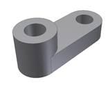
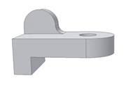
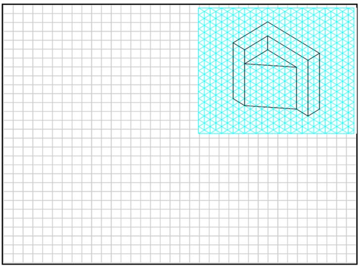
4 Study the isometric views in the next four pages. Use points, hidden lines, construction lines, and object lines to sketch the three common views used to explain the object. The scale is 1:1, which means that each grid line on the isometric view represents a grid line on the orthographic grid. DO NOT ERASE YOUR POINTS AND CONSTRUCTION LINES
5 5.


6 Extending Your Learning For each of the following, create properly aligned orthographic projections on grid paper. Use the minimum number of orthographic projections necessary to fully describe the object shown. Include object lines, hidden lines, and center lines in all views, as appropriate. The sketches should approximately proportional, but are not required to be drawn to scale
7 Conclusion 1. What is the purpose of construction lines? Object lines? 2. What is the purpose of hidden lines and center lines? 3. What type of pictorial is shown in the first representation in number 2? How can you tell? 4. What type of pictorial view is shown in number 6? How can you tell? 5. Why would building professionals, such as machinists and contractors, prefer multi-view drawings over pictorial drawings?
Activity Multiview Sketches
 Activity 1.2.4 Multiview Sketches Purpose It s a very common occurrence to see a product advertisement and think, I thought of an idea for something like that just a few months ago. People spend a lot
Activity Multiview Sketches
 Activity 1.2.4 Multiview Sketches Introduction It s a very common occurrence to see a product advertisement and think, I thought of an idea for something like that just a few months ago. People spend a
Describing an Angle Bracket
 Basics of Drafting Describing an Angle Bracket Orthographic Projection Orthographic drawings represent three dimensional objects in three separate views arranged in a standard manner. Orthographic Views
Copyrighted Material. Copyrighted Material. Copyrighted. Copyrighted. Material
 Engineering Graphics ORTHOGRAPHIC PROJECTION People who work with drawings develop the ability to look at lines on paper or on a computer screen and "see" the shapes of the objects the lines represent.
Activity 2.1 Isometric Sketching
 Page 1 of 5 Activity 2.1 Isometric Sketching Introduction How do reading the face of a clock and sketching isometric pictorials relate to each other? Picture a cube in your mind. All of the surfaces of
ENGR 1182 Exam 1 First Mid Term Exam Study Guide and Practice Problems
 Spring Semester 2016 ENGR 1182 Exam 1 First Mid Term Exam Study Guide and Practice Problems Disclaimer Problems in this study guide resemble problems relating mainly to the pertinent homework assignments.
ENGR 1182 Midterm Exam 1: Study Guide and Practice Problems
 ENGR 1182 Midterm Exam 1: Study Guide and Practice Problems Disclaimer Problems seen in this study guide may resemble problems relating mainly to the pertinent homework assignments. Reading this study
At the conclusion of this unit you should be able to accomplish the following with a 70% accuracy
 7 Multiview Drawing OBJECTIVES At the conclusion of this unit you should be able to accomplish the following with a 70% accuracy 1. explain the importance of mulitview drawing as a communication tool far
Chapter 8. Technical Drawings
 Chapter 8 Technical Drawing Technical Drawings Multiview drawings Also called three-view drawings Simple objects take three views Front, top, one side Title block Identifies who did the design Gives date,
Page 1 of 5. ENGINEERING SKETCHES INFORMATION SHEETS MEL02INF2430 v1.1 HEALTH & SAFETY REQUIREMENTS
 Page 1 of 5 Competenz - N Z Engineering Food & Manufacturing Industry Training Organisation Inc. ENGINEERING SKETCHES INFORMATION SHEETS MEL02INF2430 v1.1 HEALTH & SAFETY REQUIREMENTS RECORDING REQUIREMENTS:
Horizon - The horizontal line that contains the vanishing point(s) in a perspective drawing.
 in a perspective drawing.") Representing Solids Perspective Drawing A drawing where non-vertical parallel lines appear to meet at a point called a vanishing point. Example: If you look straight down a highway, it appears that the
Representing Solids Perspective Drawing A drawing where non-vertical parallel lines appear to meet at a point called a vanishing point. Example: If you look straight down a highway, it appears that the
Pictorial Drawings. DFTG-1305 Technical Drafting Prepared by Francis Ha, Instructor
 DFTG-1305 Technical Drafting Prepared by Francis Ha, Instructor Pictorial Drawings Geisecke s textbook for reference: 14 th Ed. Ch. 15: p. 601 Ch. 16: p. 620 15 th Ed. Ch. 14: p. 518 Ch. 15: p. 552 Update:
Student Name: Teacher: Date: District: Rowan. Assessment: 9_12 T and I IC61 - Drafting I Test 1. Description: Unit C - Sketching - Test 2.
 Student Name: Teacher: Date: District: Rowan Assessment: 9_12 T and I IC61 - Drafting I Test 1 Description: Unit C - Sketching - Test 2 Form: 501 1. The most often used combination of views includes the:
Graphical Communication
 Chapter 9 Graphical Communication mmm Becoming a fully competent engineer is a long yet rewarding process that requires the acquisition of many diverse skills and a wide body of knowledge. Learning most
Chapter 5 Pictorial sketching
 Chapter 5 Pictorial sketching Contents Freehand sketching techniques Pictorial projections - Axonometric - Oblique Isometric projection vs isometric sketch Isometric sketch from an orthographic views Isometric
Project 4.1 Puzzle Design Challenge Rubric Two potential solutions
 Project 4.1 Puzzle Design Challenge Rubric Two potential solutions Elements Weight 5 Points 4 Points 3 Points 2 Points 1-0 Points Total Activity 4.1a Puzzle Part Puzzle Parts Documentation 27 unique combinations
Technological Design Mr. Wadowski. Orthographic & Isometric Drawing Lesson
 Technological Design Mr. Wadowski Orthographic & Isometric Drawing Lesson TOPICS Working Drawings, Isometric Drawings & Orthographic Drawings Glass box concept Multiview projection Orthographic projection
2.000 Sketching Example: Tractor transmission
 1. HAVE A PLAN:Look at the transmission from the angle you want to draw it from choose an angle that will show the most information. Here we choose to draw an oblique sketch for clarity and simplicity.
Orthographic Drawing (Architectural Board Drafting)
") Design and Drafting Description In this activity, the teacher will introduce orthographic projection, in which a multi-view drawing shows how the sides of an object are related to each another. Students
Design and Drafting Description In this activity, the teacher will introduce orthographic projection, in which a multi-view drawing shows how the sides of an object are related to each another. Students
UNIT 5a STANDARD ORTHOGRAPHIC VIEW DRAWINGS
 UNIT 5a STANDARD ORTHOGRAPHIC VIEW DRAWINGS 5.1 Introduction Orthographic views are 2D images of a 3D object obtained by viewing it from different orthogonal directions. Six principal views are possible
Project 4.1 Puzzle Design Challenge
 Project 4.1 Puzzle Design Challenge Introduction Have you ever looked at a product that has been well-designed? Do you find yourself asking questions such as, How did the designer think of that idea? or
Aircraft Drawing and Blueprint Reading
 Aircraft Drawing and Blueprint Reading Course Introduction Types of drawings Engineering also known as production or working drawings. Block diagram Types of Drawings Schematics Sketches Charts and graphs
Industrial Technology Graphics Technologies
 2010 HIGHER SCHOOL CERTIFICATE EXAMINATION Industrial Technology Graphics Technologies Total marks 40 General Instructions Reading time 5 minutes Working time 1 1 hours 2 Write using black or blue pen
ORTHOGRAPHIC PROJECTIONS. Ms. Sicola
 ORTHOGRAPHIC PROJECTIONS Ms. Sicola Objectives List the six principal views of projection Sketch the top, front and right-side views of an object with normal, inclined, and oblique surfaces Objectives
Project 4.1 Puzzle Design Challenge
 Project 4.1 Puzzle Design Challenge Introduction Have you ever looked at a product that has been well-designed? Do you find yourself asking questions such as, How did the designer think of that idea? or
Study Unit. Auxiliary Views. This sneak preview of your study material has been prepared in advance of the book's actual online release.
 Study Unit Auxiliary Views This sneak preview of your study material has been prepared in advance of the book's actual online release. iii Preview You re entering now into another subject area in your
Sketching in SciTech. What you need to know for graphic communication
 Sketching in SciTech What you need to know for graphic communication Sketching in your Logbook Use pencil Take up the WHOLE PAGE Label things 1. Proportion Each part of the sketch is the right size,
CAD Mechanical Design I
 EXAM INFORMATION Items 58 Points 85 Prerequisites NONE Course Length ONE SEMESTER Career Cluster ARCHITECTURE AND CONSTRUCTION MANUFACTURING SCIENCE, TECHNOLOGY, ENGINEERING AND MATHEMATICS Performance
Marks. Total. Fill in these boxes and read what is printed below. Forename(s) Surname. Date of birth
 Surname. Date of birth") 1 2 3 4 7 KI DA C STAPLE HERE FOR OFFICIAL USE 1330/31/01 NATIONAL QUALIFICATIONS 2013 THURSDAY, 16 MAY 1.00 PM 2.4 PM GRAPHIC COMMUNICATION STANDARD GRADE Credit Level Fill in these boxes and read what
1 2 3 4 7 KI DA C STAPLE HERE FOR OFFICIAL USE 1330/31/01 NATIONAL QUALIFICATIONS 2013 THURSDAY, 16 MAY 1.00 PM 2.4 PM GRAPHIC COMMUNICATION STANDARD GRADE Credit Level Fill in these boxes and read what
ENGINEERING DRAWING SKKK 1021 ISOMETRIC DRAWING. Agus Arsad, Azizul Azri Bin Mustaffa 10/2/2012 1
 ENGINEERING DRAWING SKKK 1021 ISOMETRIC DRAWING Agus Arsad, Azizul Azri Bin Mustaffa 10/2/2012 1 LEARNING OUTCOMES ISOMETRIC DRAWING It is expected that students will be able to: Understand the significance
ORTHOGRAPHIC PROJECTION
 ORTHOGRAPHIC PROJECTION INTRODUCTION Any object has three dimensions, that is, length, width and thickness. A projection is defined as a representation of an object on a two dimensional plane. The projections
Learning Objectives. Understand the vocabulary related to Isometric Sketching Be able to create Isometric Sketches using the Box method.
 Isometric Sketching Learning Objectives Understand the vocabulary related to Isometric Sketching Be able to create Isometric Sketches using the Box method. Isometric Pictorial Isometric means equal measure.
11/12/2015 CHAPTER 7. Axonometric Drawings (cont.) Axonometric Drawings (cont.) Isometric Projections (cont.) 1) Axonometric Drawings
 Axonometric Drawings (cont.) Isometric Projections (cont.) 1) Axonometric Drawings") CHAPTER 7 1) Axonometric Drawings 1) Introduction Isometric & Oblique Projection Axonometric projection is a parallel projection technique used to create a pictorial drawing of an object by rotating the
CHAPTER 7 1) Axonometric Drawings 1) Introduction Isometric & Oblique Projection Axonometric projection is a parallel projection technique used to create a pictorial drawing of an object by rotating the
Honors Drawing/Design for Production (DDP)
") Honors Drawing/Design for Production (DDP) Unit 1: Design Process Time Days: 49 days Lesson 1.1: Introduction to a Design Process (11 days): 1. There are many design processes that guide professionals
Honors Drawing/Design for Production (DDP) Unit 1: Design Process Time Days: 49 days Lesson 1.1: Introduction to a Design Process (11 days): 1. There are many design processes that guide professionals
Project 4.1 Puzzle Design Challenge Rubric
 Project 4.1 Puzzle Design Challenge Rubric Elements Weight 5 Points 4 Points 3 Points 2 Points 1-0 Points Total Activity 4.1a Puzzle Part Puzzle Parts Documentation Multiple combinations of three, four,
TECHNICAL DESIGN I (540)
") DESCRIPTION The first assessment in a series, Technical Design I prepares students to develop technical knowledge and skills required to plan and prepare scale pictorial interpretations of engineering
DESCRIPTION The first assessment in a series, Technical Design I prepares students to develop technical knowledge and skills required to plan and prepare scale pictorial interpretations of engineering
Isometric Drawing (Architectural Board drafting)
") Design and Drafting Description Isometric drawings use perspective to communicate a large amount of information in a single drawing. Isometric drawings show three sides of an object, making it easier to
Design and Drafting Description Isometric drawings use perspective to communicate a large amount of information in a single drawing. Isometric drawings show three sides of an object, making it easier to
ORTHOGRAPHIC PROJECTION
 ORTHOGRAPHIC PROJECTION C H A P T E R S I X OBJECTIVES 1. Recognize and the symbol for third-angle projection. 2. List the six principal views of projection. 3. Understand which views show depth in a drawing
DMT113 Engineering Drawing. Chapter 3 Stretch System
 DMT113 Engineering Drawing Chapter 3 Stretch System Contents Theory & Multiview Planes 6 Principle Views Multiview Sketching Technique & Perspective First & Third Angle Multiview Representations Theory
Activity 7.1 More Dimensioning
 Activity 7.1 More Dimensioning Introduction The basic standard dimensioning method established by the American National Standards Institute and the American Society of Mechanical Engineers (ANSI or ASME)
To start a new drawing Select File New then from the dialog box, which appears select Normal.dft followed by OK.
 Draft Tutorial This tutorial provides step-by-step instructions for the detailing of a drawing of the anchor block shown opposite. As you create this drawing, you will use the following drafting techniques:
1. When sketching long, narrow objects in OBLIQUE, distortion can be lessened by placing the long dimension along:
 Draft Student Name: Teacher: District: Date: Wake County Test: 9_12 T and I IC61 - Drafting I Test 2 Description: 3.03 Apply 3D sketching Form: 501 1. When sketching long, narrow objects in OBLIQUE, distortion
T&E Express SCSU Mobile Lab Program
 T&E Express SCSU Mobile Lab Program Course : Industrial Technology 8 Science Strand and Substrand being addressed Develop a model to generate data for iterative testing and modification of a proposed object,
Interpretation of Drawings. An Introduction to the Basic Concepts of Creating Technical Drawings
 Interpretation of Drawings An Introduction to the Basic Concepts of Creating Technical Drawings Introduction In the design process drawings are the main way in which information about an object or product
Assignment 12 CAD Mechanical Part 2
 Assignment 12 CAD Mechanical Part 2 Objectives In this assignment you will learn to apply the hidden lines, isometric snap, and ellipses commands along with commands previously learned.. General Hidden
Drafting: Orthographic and Isometric Drawings
 Youth Explore Trades Skills Description Students will learn to develop and interpret plumbing drawings typically found in construction. There are two parts to this lesson: Part 1: Orthographic drawings
Fundamentals for building Drawing
 Fundamentals for building Drawing What is Drawing Introduction Knowledge of preparing and understanding drawing will prove to be an invaluable aid while performing their jobs effectively, efficiently.
Engineering Drawing I
 Instructional Unit Advanced Assembly Drawings -Introduction To Types of Assembly Drawings. -Students will be able -Identify component Class Discussions 3.1.10.B, to identify the details information in
Course Title: Mechanical Drawing Topic/Concept: Views Of Objects Time Allotment: 3 6 Weeks Unit Sequence: 1 Major Concepts to be learned:
 Course Title: Mechanical Drawing Topic/Concept: Views Of Objects Time Allotment: 3 6 Weeks Unit Sequence: 1 1. Sketching skills 2. Orthographic projection 3. Visualization of views 4. Location of lines
-SQA-SCOTTISH QUALIFICATIONS AUTHORITY. Hanover House 24 Douglas Street GLASGOW G2 7NQ NATIONAL CERTIFICATE MODULE DESCRIPTOR
 -SQA-SCOTTISH QUALIFICATIONS AUTHORITY Hanover House 24 Douglas Street GLASGOW G2 7NQ NATIONAL CERTIFICATE MODULE DESCRIPTOR -Module Number- 0095602 -Session-1989-90 -Superclass- TD -Title- CONSTRUCTION
Related Drafting. (Construction related trades)
") (Construction related trades) I. Course Description Related Drafting This course is broken up into 36 weeks. The main goal of this course is to introduce construction related trades the necessary skills
(Construction related trades) I. Course Description Related Drafting This course is broken up into 36 weeks. The main goal of this course is to introduce construction related trades the necessary skills
EDUCATIONAL REND LAKE COLLEGE CAD INTRODUCTION TO COMPUTER-AIDED DRAFTING ISOMETRIC DRAWING REVISED: FALL 2010 INSTRUCTOR: THOMAS ARPASI
 INSTRUCTOR: THOMAS ARPASI REND LAKE COLLEGE CAD 1201-51 INTRODUCTION TO COMPUTER-AIDED DRAFTING ISOMETRIC DRAWING 1 Pictoral Drawing Pictoral drawing have evolved from cave paintings to photorealistic
Multiviews and Auxiliary Views
 Multiviews and Auxiliary Views Multiviews and Auxiliary Views Objectives Explain orthographic and multiview projection. Identifying the six principal views. Apply standard line practices to multiviews
ENGINEERING DRAWING N1
 REQUIREMENTS: A2 drawing paper T590(E)(M24)T NATIONAL CERTIFICATE ENGINEERING DRAWING N1 (8090261) 24 March 2017 (X-Paper) 09:00 13:00 Drawing instruments and calculators may be used. This question paper
Technology Education Grades Drafting I
 Technology Education Grades 9-12 Drafting I 46 Grade Level: 9, 10, 11, 12 Technology Education, Grades 9-12 Drafting I Prerequisite: None Drafting I is an elective course which provides students the opportunity
Perspective Sketching
 Perspective Sketching Perspective Drawings A perspective drawing offers the most realistic three-dimensional view of all the pictorial methods, because it portrays the object in a manner that is most similar
Drawing Isometric From Orthographic View
 From View Free PDF ebook Download: From View Download or Read Online ebook drawing isometric from orthographic view in PDF Format From The Best User Guide Database Examples. 1. 2. 3 Foundation. 4 Identifying
Quick Start for Autodesk Inventor
 Quick Start for Autodesk Inventor Autodesk Inventor Professional is a 3D mechanical design tool with powerful solid modeling capabilities and an intuitive interface. In this lesson, you use a typical workflow
Lecture #4 MULTIVIEW PROJECTION RES 112E COMPUTER AIDED TECHNICAL DRAWING ITU
 Lecture #4 MULTIVIEW PROJECTION This week You will learn multi-view projection. The steps to follow are: Projections (ISO-E & ISO-A) Multi-view drawings Views (Basic,Auxiliary, Detailed etc.) Sketching
Engineering Graphics Essentials with AutoCAD 2015 Instruction
 Kirstie Plantenberg Engineering Graphics Essentials with AutoCAD 2015 Instruction Text and Video Instruction Multimedia Disc SDC P U B L I C AT I O N S Better Textbooks. Lower Prices. www.sdcpublications.com
Creating a 2D Drawing in Paper Space
 C h a p t e r 16 Creating a 2D Drawing in Paper Space In this chapter, we will learn the following to World Class standards: 1. Converting 3D Solids to 2D Orthographic Views 2. Open the Solid Part Drawing
Multiview Drawing. Definition: Graphical representation of a 3- dimensional object on one plane (sheet of paper) using two or more views.
 using two or more views.") Multiview Drawing Definition: Graphical representation of a 3- dimensional object on one plane (sheet of paper) using two or more views. Multiview Drawing Another name for multiview drawing is orthographic
Multiview Drawing Definition: Graphical representation of a 3- dimensional object on one plane (sheet of paper) using two or more views. Multiview Drawing Another name for multiview drawing is orthographic
Sketching Technique Examples
 Sketching Technique Examples Session Speaker Asst. Prof. DOD 1 Session Objectives At the end of this session the delegate would have understood 1. How to create a transmission using pencils 2. How to create
ENGINEERING GRAPHICS ESSENTIALS
 ENGINEERING GRAPHICS ESSENTIALS with AutoCAD 2012 Instruction Introduction to AutoCAD Engineering Graphics Principles Hand Sketching Text and Independent Learning CD Independent Learning CD: A Comprehensive
Introduction to AutoCAD 2010
 Page 1 Introduction to AutoCAD 2010 Alf Yarwood Chapter 7 Exercise 1 1. Open AutoCAD 2010 with a double-click on its shortcut icon in the Windows desktop. 2. Open the template acadiso.dwt. 3. Call the
Isometric Drawings. Figure A 1
 A Isometric Drawings ISOMETRIC BASICS Isometric drawings are a means of drawing an object in picture form for better clarifying the object s appearance. These types of drawings resemble a picture of an
Civil Engineering Drawing
 Civil Engineering Drawing Third Angle Projection In third angle projection, front view is always drawn at the bottom, top view just above the front view, and end view, is drawn on that side of the front
Graphical Communication for Engineering ENSC 204 Final Exam
 Name: Student #: Graphical Communication for Engineering ENSC 204 Final Exam December 16, 2015 Time: 3 hours CLOSED BOOK EXAM Read all the instructions below. Do NOT start the exam until you are told to.
Drawing Types & Construction Drawings
 Drawing Types & Construction Drawings Building projects require several types of specialised drawings. This collection of drawings, known as a project set, includes: Location Plan Site Plan Floor Plan
CAD and Drafting Standards Working Drawings
 CAD and Drafting Standards Working Drawings Gregory Mocko Introduction 2 The purpose of drawing or generating a CAD document is to communicate Essentially, since communication is the goal, some standards
Add labels to the sides...
 Orthographic Drawings Orthographic Projection A projection on a plane, using lines perpendicular to the plane Graphic communications has many forms. Orthographics is one such form. It was developed as
Including: Synthesis of Ideas Justification and Recording Decisions Taken Presentation Techniques Modelling Techniques
 Development & Refinement Including: Synthesis of Ideas Justification and Recording Decisions Taken Presentation Techniques Modelling Techniques Synthesis of Ideas Designers often start off with lots of
Production drawing Diagram. a) I am a freehand drawing that follows technical drawing standards.
 I am a freehand drawing that follows technical drawing standards.") THE TECHNOLOGICAL WORLD Graphical language STUDENT BOOK Ch. 11, pp. 336 342 Basic lines, geometric lines, sketches 1. In technology, the two most widely used types of technical drawings are: a) sketch
THE TECHNOLOGICAL WORLD Graphical language STUDENT BOOK Ch. 11, pp. 336 342 Basic lines, geometric lines, sketches 1. In technology, the two most widely used types of technical drawings are: a) sketch
I B.TECH- I SEMESTER DEPARTMENT OF MECHANICAL ENGINEERING ENGINEERING DRAWING
 I B.TECH- I SEMESTER DEPARTMENT OF MECHANICAL ENGINEERING ENGINEERING DRAWING ENGINEERING DRAWING UNIT-V DEFINITIONS: Axonometric Trimetric Dimetric Isometric It is a parallel technique used to create
technical drawing
 technical drawing school of art, design and architecture nust spring 2011 http://www.youtube.com/watch?v=q6mk9hpxwvo http://www.youtube.com/watch?v=bnu2gb7w4qs Objective abstraction - axonometric view
ISOMETRIC PROJECTION. Contents. Isometric Scale. Construction of Isometric Scale. Methods to draw isometric projections/isometric views
 ISOMETRIC PROJECTION Contents Introduction Principle of Isometric Projection Isometric Scale Construction of Isometric Scale Isometric View (Isometric Drawings) Methods to draw isometric projections/isometric
IED Detailed Outline. Unit 1 Design Process Time Days: 16 days. An engineering design process involves a characteristic set of practices and steps.
 IED Detailed Outline Unit 1 Design Process Time Days: 16 days Understandings An engineering design process involves a characteristic set of practices and steps. Research derived from a variety of sources
Lesson Plan. Preparation
 Lesson Plan Course Title: Engineering Design and Presentation Session Title: Sketching Performance Objective: Upon completion of this lesson, the students will be able to sketch ideas/problems/products
Spatial Sense 4-1 PRINCE EDWARD ISLAND APPLIED MATHEMATICS 801A
 Spatial Sense 4-1 Table of Contents Spatial Sense Constructing Shapes from Mat Plans... 4-3 Constructing 3-view Orthographic Projections from Mat Plans... 4-4 Constructing Mat Plans from 3-View Orthographic
Chapter 1 Introduction
 Chapter 1 Introduction Contents Engineering drawing Drawing standards Drawing sheet Scale Lettering Line types Engineering Drawing Contents Engineering Drawing Effectiveness of Graphic Language 1. Try
Anchor Block Draft Tutorial
 Anchor Block Draft Tutorial In the following tutorial you will create a drawing of the anchor block shown. The tutorial covers such topics as creating: Orthographic views Section views Auxiliary views
ENGINEERING GRAPHICS ESSENTIALS
 ENGINEERING GRAPHICS ESSENTIALS with AutoCAD 2012 Instruction Introduction to AutoCAD Engineering Graphics Principles Hand Sketching Text and Independent Learning CD Independent Learning CD: A Comprehensive
7048/01 October/November hours 30 minutes. Sheet 1 of 3. Complete the drawing below to show the six pieces of Styrofoam required to make the
 Complete the drawing below to show the six pieces of Styrofoam required to make the mug. [6] For Examiner s Use Sheet 1 of 3 Section A (c) Add the thick and thin line technique to the sketch of the handle
60 Most Important Engineering Drawing Questions
 1. If a client of yours is having difficulty visualizing a design, what type of drawing would be the easiest to understand? A. axonometric B. three-view orthographic C. one-view orthographic D. bimetric
Pull Down Menu View Toolbar Design Toolbar
 Pro/DESKTOP Interface The instructions in this tutorial refer to the Pro/DESKTOP interface and toolbars. The illustration below describes the main elements of the graphical interface and toolbars. Pull
Exploded View Extracting Drawings. ENGR 1182 SolidWorks 08
 Exploded View Extracting Drawings ENGR 1182 SolidWorks 08 Today s Objectives Formal Drawing Components: Exploded View Extracted Drawings SW07 Activity SW07 Application Formal Drawings Definition: First
FACTFILE: GCE TECHNOLOGY & DESIGN
 FACTFILE: GCE TECHNOLOGY & DESIGN 1.8, 1.26, 1.56 DESIGN AND COMMUNICATION Design and Communication Learning outcomes Students should be able to: communicate designs using 2D methods, to include freehand
Orthographic Drawings
 Orthographic Drawings You don t have to be an artist to draw great furniture plans. By Craig Bentzley W oodworking requires a graphic language to convey building information. We can t do it without drawings
The project focuses on the design for a Pencil holder, but could be adapted to any simple assembly.
 Introduction - Teacher Notes Fig 1. The project focuses on the design for a Pencil holder, but could be adapted to any simple assembly. Pro/DESKTOP enables pupils (and teachers) to communicate and model
FLUX: Design Education in a Changing World. DEFSA International Design Education Conference 2007
 FLUX: Design Education in a Changing World DEFSA International Design Education Conference 2007 Use of Technical Drawing Methods to Generate 3-Dimensional Form & Design Ideas Raja Gondkar Head of Design
*X033/12/01* X033/12/01 HIGHER STAPLE HERE NATIONAL QUALIFICATIONS. 8 Orthographic drawings are in third angle projection.
 Question 2 3 4 Section A Total 7a 7b 8 9 0 EITHER OR 2 Section B Total Total Marks A + B Marks STAPLE HERE FOR OFFICIAL USE 033/2/0 NATIONAL QUALIFICATIONS 204 THURSDAY, 8 MAY.00 PM 4.00 PM GRAPHIC COMMUNICATION
ENGINEERING GRAPHICS ESSENTIALS
 ENGINEERING GRAPHICS ESSENTIALS Text and Digital Learning KIRSTIE PLANTENBERG FIFTH EDITION SDC P U B L I C AT I O N S Better Textbooks. Lower Prices. www.sdcpublications.com ACCESS CODE UNIQUE CODE INSIDE
DRAFT MECHANICAL DRAWING
 Industrial Technology History of Drafting 9-12 Curriculum Standard One: The student will understand, classify, and be familiar with historical events, from cave writings to computer aided drafting systems,
Fundamentals of Drafting - Orthographic Projection with Hidden Details
 Fundamentals of Drafting - Orthographic Projection with Hidden Details Objectives: 1. To extend the principle of orthographic projection for hidden details. 2. To illustrate the representation of hidden
C A R I B B E A N E X A M I N A T I O N S C O U N C I L REPORT ON CANDIDATES WORK IN THE SECONDARY EDUCATION CERTIFICATE EXAMINATION MAY/JUNE 2010
 C A R I B B E A N E X A M I N A T I O N S C O U N C I L REPORT ON CANDIDATES WORK IN THE SECONDARY EDUCATION CERTIFICATE EXAMINATION MAY/JUNE 2010 TECHNICAL DRAWING GENERAL PROFICIENCY Copyright 2010 Caribbean
Beginning Engineering Graphics 3 rd Week Lecture Notes Instructor: Edward N. Locke Topic: The Coordinate System, Types of Drawings and Orthographic
 Beginning Engineering Graphics 3 rd Week Lecture Notes Instructor: Edward N. Locke Topic: The Coordinate System, Types of Drawings and Orthographic 1 st Subject: The Cartesian Coordinate System The Cartesian
ME1105 Engineering Drawing & Design
 City University London Term 1 Assessment 2008/2009 School of Engineering and Mathematical Sciences ME1105 Engineering Drawing & Design Student Name:.., Group: Examination duration: Reading time: This paper
CLASS views from detail on a grid paper. (use appropriate line types to show features) - Optional views. Turn in for grading on class 6 (06/04)
 - Optional views. Turn in for grading on class 6 (06/04)") CLASS 4 Review: - Projections - Orthographic projections Lab: - 3 views from detail on a grid paper. (use appropriate line types to show features) - Optional views. Turn in for grading on class 6 (06/04)
CLASS 4 Review: - Projections - Orthographic projections Lab: - 3 views from detail on a grid paper. (use appropriate line types to show features) - Optional views. Turn in for grading on class 6 (06/04)
Chapter 8. Piping Isometrics
 Chapter 8 Piping Isometrics An isometric drawing is a type of pictorial drawing in which three sides of an object can be seen in one view. It s popular within the process piping industry because it can
TECHNICAL DRAWING & DESIGN
 MINISTRY OF EDUCATION FIJI SCHOOL LEAVING CERTIFICATE EXAMINATION 2011 TECHNICAL DRAWING & DESIGN COPYRIGHT: MINISTRY OF EDUCATION, REPUBLIC OF THE FIJI ISLANDS 2. MINISTRY OF EDUCATION FIJI SCHOOL LEAVING