FLUX: Design Education in a Changing World. DEFSA International Design Education Conference 2007
|
|
|
- Rosemary Ball
- 5 years ago
- Views:
Transcription
1 FLUX: Design Education in a Changing World DEFSA International Design Education Conference 2007 Use of Technical Drawing Methods to Generate 3-Dimensional Form & Design Ideas Raja Gondkar Head of Design Department Indian Institute of Gems & Jewellery (IIGJ) Mumbai, India Address: 502, A Wing, Tulsi Tower Plot 44, RSC 6, MHADA Layout Malvani, Malad-West Mumbai , India Tel.: Cell: rajagondkar@gmail.com ********************************************************************************************
2 Use of Technical Drawing Methods to Generate 3-Dimensional Form & Design Ideas Problem being addressed: Abstract Generally speaking technical drawing methods e.g. isometric and orthographic views are used for presentation of form and design idea. Systematically used these methods can yield fantastic results serving as a tool in the form and design generation / development process. In various product domains, especially where sheer aesthetic appeal or plurality of form is more important than functionality or utility; development of form family, variations on theme, etc. are the main design activity. This way of working will serve as an effective tool in cases where the design development process is confined mostly to the paperwork only but the product demands or has a scope for 3- Dimensional thinking e.g. industrial jewelry design. Approach: Viewed individually, orthographic views could be interpreted in more then one way; using this ambiguity as a form manipulation device many forms or a family of forms could be developed. Further addition of spontaneous or methodical form-variation increases manifold the number and variation possibilities. Constructing and employing various project / domain / user-specific grids as tools in the form and design development process makes it easy to handle 3-Dimentional form variations on (2- Dimensional) paper. 3-D CAD software which are primarily used for making models / prototypes, once the design is ready, also can become effective and potentially integral part of the entire form and design development process right from the initial stages. Conclusion: Systematic use of various project / domain / user specific grids as tools makes handling of 3- Dimestional space in 2-Dimentional environment possible and easier too. This can help the designers as well as novice students in handling relatively complex 3-Dimestional forms. Key Words: design development, form generation, technical drawing


3 Introduction Human spatial perception Our spatial perception is based on our ability to integrate the multiple views seen simultaneously or in succession while rotating the object in hand or moving around it. Figure 1: Our spatial perception is based on our ability to integrate the multiple views Variety in design experience The reality that the human eye can see only the confronting / partial view of an object can be used to provide variety in design experience or even to deceive our expectancies. Some engaging variation or surprise can be planed on the hidden or next reveling view. Figure 2: Design concept for two-way pendant where front and back provide two different looks Figure 3: It is possible to provide some spatially animated experience by purposeful planning. We look for common elements and pattern to understand the coherent relationships between the multiple views. In context of a set or a collection (of objects), group or family of forms comes in


4 consideration. Multiple forms having complementary or matching set of elements / characteristics form a group. While negative-positive form-space relationship provides basis for complementary and modular group of forms; form families can be based on the premises of, same origin / underling framework or methodology applied in the form generation / development process. Figure 4: Design concept for a set of pendant & earring based on negative-positive form-space relationship. Figure 5: Forms derived from the same origin / underling framework produces familiar forms. Geometric projections are basic to all the technical drawings, understanding and developing geometric relations between different views, understanding complex form contours and structures by finding its basic geometry or relationship with the surrounding space / elements is a usual task of any one working with technical drawings. Using these very tasks as tools in 3D form generation / development is the idea explored in this paper. Using technical drawings methods for 3D form generation and development Technical drawings (e.g. isometric, orthographic projections, etc.) are used to convey the true form and dimensions / proportions of the intended object; the objective with them is to leave no room for ambiguity and avoid any miss-interpretation. Figure 6: Orthographic and isometric views of an object.
5 Our premises here is, systematic use of these methods yields fantastic results; serving as a tool in the form and design generation / development process. Various pictorial as well as technical drawing methods, used mainly for representing or explaining 3-D forms and objects on 2-D paper can be used methodically to conceive, view, analyze, and develop 3-D forms from various view points. In this context we will look more into the following; Exploring and exploiting inherent ambiguity or deliberate plural interpretations of various orthographic views. Explorations of form and space using technical / pictorial drawing methods with the intentions of creation and development of form(s). o o Developing a pre determined / finite form-space Use of infinite grids Project or domain specific form development: an example Exploring and exploiting inherent ambiguity or deliberate plural interpretations of orthographic views Orthographic views provide flat, 2-dimensional understanding of form contour and proportions without complicating it by inclined distortions. There are 6 principal sides to any form; front & back, top & bottom, and two of the sides respectively; hence 6 orthographic views. Generally 3 adjoining views provide enough information for understanding of the form in total. Figure 7: Six principal orthographic views Figure 8: Three adjoining orthographic projections
6 Orthographic views are uniplaner projections of 3-D forms, they lack perception of depth. Representational drawings show contours and folds in line; thus orthographic views, especially seen singularly provide an opportunity for multiple interpretations. For example a drawn circle as one of the orthographic views could be interpreted as a disk, a cylinder, a bullet, a sphere or a semi-sphere. Figure 9 a: Plan Figure 9 b: Various possible interpretation of a plan in figure 9 a Add one more concentric circle to it and the inner circle could be interpreted as a negative space or a sub-form-element; this suggests several possibilities; it could be interpreted as; a disk with a hole or an elevated step, a depression, a dome or a sphere in the centre; a sphere or a cylinder with a hole or rod in the centre; a segment of a cone; a donut; a hat shape; so and so... Figure 9 c: Plan Figure 9 d: Various possible interpretation of a plan in figure 9 c All these forms share a common plan view; a creative designer can explore and exploit this potential as a form generation tool to develop an array of familiar forms with variations. Once an exercise sparks an idea, a scheme of design, the designer is free to take creative liberties and modify the original orthographic view or forms suitably. Going beyond the obvious there are infinite possibilities with any of the views however simple they could be.

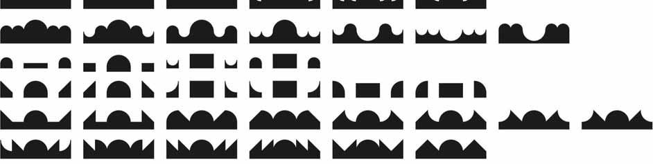


7 Figure 9 e: Innumerous possibilities from a single plan view
, are used mainly for representing 3-D forms and objects on 2-D paper. They represent the form in a pictorial manner i.e. also showing the depth in a single view (as against orthographic views where more then one view is needed to provides adequate information).")
8 Explorations of form and space using technical / pictorial drawing methods with the intentions of creation and development of form(s) Pictorial drawing methods (e.g. oblique, isometrics, perspective drawing, etc.), are used mainly for representing 3-D forms and objects on 2-D paper. They represent the form in a pictorial manner i.e. also showing the depth in a single view (as against orthographic views where more then one view is needed to provides adequate information). Any of the pictorial drawing methods could be used in form explorations; it is only matter of individual convenience, complexity of form and time at hand. Here we will look in to oblique views as they can be realized from orthographic views in a quick manner and isometric drawings as they provide balanced viewing angle with adjoining sides representing all three dimensions at a glance. Oblique View Oblique views provide simple pictorial realization of 3 D form by adding the missing depth to an appropriate (generally front) orthographic view with extended oblique lines. Figure 10: Oblique views enable the designer to add the missing depth to any of the orthographic views and get the pictorial perception in a quick manner. Isometric View Figure 11: Isometric view shows three principal dimensions at a glance Isometric projections and drawings provide optimum possible and balanced viewing angle of the form by showing 3 principal dimensions, 3 adjoining sides at a glance. By providing even better a pictorial view than an oblique view this helps in perceiving the spatial relations among the form contours as well as dimensional proportions. There are 8 possible isometric viewing angles representing 8 corners of any 3 dimensional form. Drawings of all the important ones in proximity provide the designer with simultaneous understanding of the form in its entirety and a basis for visualization of possible variations, modifications and developments or reorganization of sub-form elements. Step by step methodical developments transform the basic form to its aesthetic perfection or provide a range of options depending on the designer s objective.
9 Figure12: Possible isometric viewing angles representing 8 corners Practical understanding and skillful handling of 3-D drawing methods, makes exploration / experimentation / realization part in a designing process faster, easier and interesting. Apart from conceiving, viewing, analyzing, and developing 3-D forms this methodology helps also in problem solving related to mechanisms, measurements, etc. This practice also helps in developing logical thinking ability, very crucial for any 3-D designer. Possible approaches in form development using 3 D / pictorial drawing methods There can be possibly two approaches in form development by using 3D drawing methods; developing a finite space, where a suitable or predetermined finite space can be used as a starting point or use of infinite grid of suitable units. Developing a finite space A simple cubic (or any other geometric solids) space could be developed in to a meaningful interesting form by methodical and logical use of some internal (or external) reference points to add and / or subtract a space / form element. To initiate a form development process, apart from any basic or improvised geometric solid form, it is also possible to begin with any other existing or developed form for the purpose. Similarly any 2 D form also can be projected in any of the suitable 3 D drawing methods and by adding appropriate depth to it to be used as an initiating form. Figure 13: Some internal or external reference points related to the finite space could be used in form modification / development Further, to carryout measured modifications, the designer needs to mark some logical reference points within or outside the form. This could be done by logical use of form contour, by dividing the form space, or using some scaling device. These reference points could be then used to modify the form by addition, deletion, modification or reorganization, etc.

10 Use of space division methods Methodical space division provides an internal grid of reference points within the space. These reference points can be used to mark, divide, subtract or add space in a proportionate manner. This not only provides the designer a systematic tool for manipulation of form, it also helps in developing forms with inherently structured proportions. Figure 14: Space division methods Figure 15: Form development by space division methods Use of grids Made of self repeating units, grids are of infinite nature. It is useful to use relevant basic grids to help quick realization of form on paper; respectively square grid for orthographic views, combined square & diamond grid for oblique views and hexagonal grid for isometric views are especially useful. Figure 16: Useful basic grids

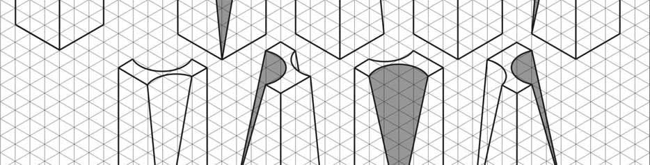
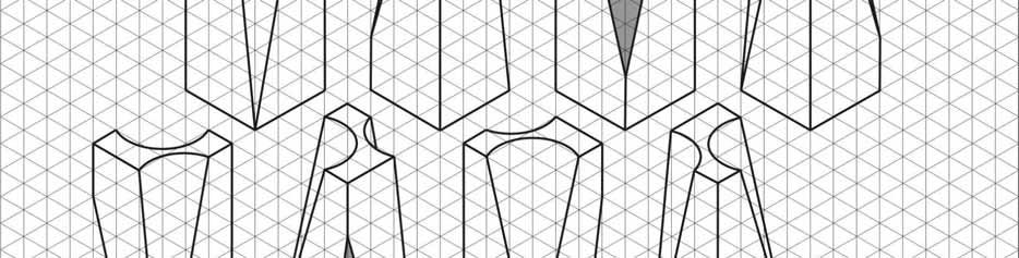
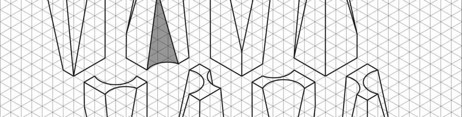
11 Figure 17: 3D form development example


12 Apart from basic grids it is also possible to use various different kinds of grids in the form development process; many variants, combinations and distortions of basic grids are possible. It is possible to use methodical distortions in the form development process. Contour proportions and form specific internal reference points could be manipulated in distortion of forms in a logical methodical manner. The basic grids could be distorted with certain parameters and used to realize the distorted forms in an efficient manner. Figure 18: Distorted Grid / Form Examples Project or domain specific form development: an example of bangles bracelets Project or domain specific grids (and set of rules / constraints) could be developed for directing or ease of working in the form development process; in achieving certain characteristics or kind of forms or accommodating prefixed elements in an overall scheme. Hear we will see domain specific example of using specially developed grids to generate design ideas for bangle bracelets. Bangle bracelets are either circular or oval-shaped, we will see circular. They are either slip-on type fixed or hinged to open. Both types are possible to be designed using these grids. It is also possible to develop designs with overall self repeating pattern, or designs with asymmetrical sections. First grid is circular grid with even divisions to generate plan views. The second one is the same grid projected on isometric plane, to develop the plan view for depth and work on elevation. Figure 19: Project specific grids devised for development of forms suitable for bangle bracelets


13 Figure 20: Basic steps involved in developing a simple bangle form patterns


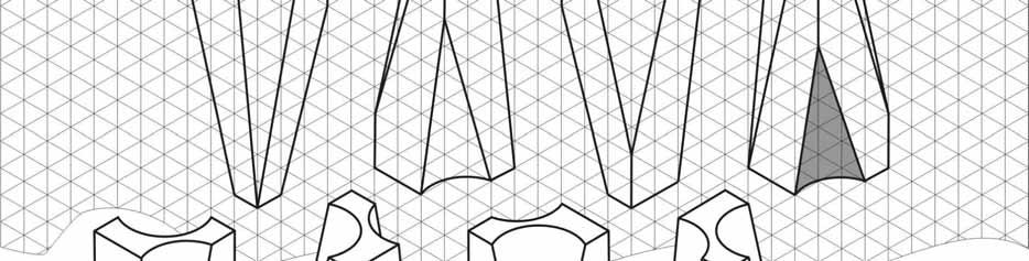
14 Figure 21: Some of the bangle forms developed by the students using grids
15 Conclusion To provide variety, an important aspect in the design experience, it is basically essential to look at various possibilities. When a singular form needs to look interesting from all the viewing points; multiple forms must compliment each other or share some common characteristics. The very tasks involved in technical drawing making can be used as effective tools in 3D form generation / development with inherently structured proportions. Orthographic views, especially seen singularly provide an opportunity for multiple interpretations. Any of the pictorial drawing methods could be used in form explorations; either by developing a suitable / predetermined finite space where the methodical space division provides an internal grid of reference points or by using an infinite grid of suitable units. It is also possible to develop project or domain specific grids for directing the form development process to achieve certain characteristics or kind of forms.
16 CURRICULUM VITAE A graduate in Applied Arts from Sir J J Institute of Applied Arts, Mumbai; Raja Gondkar is currently heading the Design Department of the Indian Institute of Gems & Jewellery, Mumbai, India. Here he is responsible for development and running of design related courses, training of faculty and students. He has been active for now over 20 years in various art & design domains like advertising graphics, product design, poetry and other literary arts, apart from Jewellery. Last over a decade he has diverted to the academic side of Jewellery and has been involved in development of various courses ranging from short term to longer duration diplomas; training materials, study manuals and imparting training in the field of Jewellery Design & Manufacture with several institutions in India. He has many awards in Jewellery Design to his credit including Overall winner prize in bridal-wear category and a Scholarship to Europe in 1997 De Beers Indian Jewellery Design Competition. Since he has been a judge to several design competitions and writes columns for some Jewellery related magazines.
UNIT 5a STANDARD ORTHOGRAPHIC VIEW DRAWINGS
 UNIT 5a STANDARD ORTHOGRAPHIC VIEW DRAWINGS 5.1 Introduction Orthographic views are 2D images of a 3D object obtained by viewing it from different orthogonal directions. Six principal views are possible
ENGR 1182 Exam 1 First Mid Term Exam Study Guide and Practice Problems
 Spring Semester 2016 ENGR 1182 Exam 1 First Mid Term Exam Study Guide and Practice Problems Disclaimer Problems in this study guide resemble problems relating mainly to the pertinent homework assignments.
Copyrighted Material. Copyrighted Material. Copyrighted. Copyrighted. Material
 Engineering Graphics ORTHOGRAPHIC PROJECTION People who work with drawings develop the ability to look at lines on paper or on a computer screen and "see" the shapes of the objects the lines represent.
IED Detailed Outline. Unit 1 Design Process Time Days: 16 days. An engineering design process involves a characteristic set of practices and steps.
 IED Detailed Outline Unit 1 Design Process Time Days: 16 days Understandings An engineering design process involves a characteristic set of practices and steps. Research derived from a variety of sources
1 ISOMETRIC PROJECTION SECTION I: INTRODUCTION TO ISOMETRIC PROJECTION
 1 ISOMETRIC PROJECTION SECTION I: INTRODUCTION TO ISOMETRIC PROJECTION Orthographic projection shows drawings of an object in a two-dimensional format, with views given in plan, elevation and end elevation
Describing an Angle Bracket
 Basics of Drafting Describing an Angle Bracket Orthographic Projection Orthographic drawings represent three dimensional objects in three separate views arranged in a standard manner. Orthographic Views
Honors Drawing/Design for Production (DDP)
") Honors Drawing/Design for Production (DDP) Unit 1: Design Process Time Days: 49 days Lesson 1.1: Introduction to a Design Process (11 days): 1. There are many design processes that guide professionals
Honors Drawing/Design for Production (DDP) Unit 1: Design Process Time Days: 49 days Lesson 1.1: Introduction to a Design Process (11 days): 1. There are many design processes that guide professionals
Drawing Types & Construction Drawings
 Drawing Types & Construction Drawings Building projects require several types of specialised drawings. This collection of drawings, known as a project set, includes: Location Plan Site Plan Floor Plan
Multiviews and Auxiliary Views
 Multiviews and Auxiliary Views Multiviews and Auxiliary Views Objectives Explain orthographic and multiview projection. Identifying the six principal views. Apply standard line practices to multiviews
ENGR 1182 Midterm Exam 1: Study Guide and Practice Problems
 ENGR 1182 Midterm Exam 1: Study Guide and Practice Problems Disclaimer Problems seen in this study guide may resemble problems relating mainly to the pertinent homework assignments. Reading this study
Activity 2.4 Multi-view Sketching
 Activity 2.4 Multi-view Sketching Introduction It s a very common occurrence to see a product advertisement and think, I thought of an idea for something like that just a few months ago. People spend a
ORTHOGRAPHIC PROJECTION
 ORTHOGRAPHIC PROJECTION C H A P T E R S I X OBJECTIVES 1. Recognize and the symbol for third-angle projection. 2. List the six principal views of projection. 3. Understand which views show depth in a drawing
ORTHOGRAPHIC PROJECTIONS. Ms. Sicola
 ORTHOGRAPHIC PROJECTIONS Ms. Sicola Objectives List the six principal views of projection Sketch the top, front and right-side views of an object with normal, inclined, and oblique surfaces Objectives
DWG 002. Blueprint Reading. Geometric Terminology Orthographic Projection. Instructor Guide
 DWG 002 Blueprint Reading Geometric Terminology Orthographic Projection Instructor Guide Introduction Module Purpose The purpose of the Blueprint Reading modules is to introduce students to production
Graphical Communication
 Chapter 9 Graphical Communication mmm Becoming a fully competent engineer is a long yet rewarding process that requires the acquisition of many diverse skills and a wide body of knowledge. Learning most
Chapter 5 Pictorial sketching
 Chapter 5 Pictorial sketching Contents Freehand sketching techniques Pictorial projections - Axonometric - Oblique Isometric projection vs isometric sketch Isometric sketch from an orthographic views Isometric
Engineering Drafting and Design I
 Title Engineering Drafting and Design I Type Consensus Document Map Authors Steven Shuttlesworth, Paul Wood Subject Industrial/Technology Education Course Engineering Drafting and Design I Grade(s) 09,
FACTFILE: GCE TECHNOLOGY & DESIGN
 FACTFILE: GCE TECHNOLOGY & DESIGN 1.8, 1.26, 1.56 DESIGN AND COMMUNICATION Design and Communication Learning outcomes Students should be able to: communicate designs using 2D methods, to include freehand
Fundamentals for building Drawing
 Fundamentals for building Drawing What is Drawing Introduction Knowledge of preparing and understanding drawing will prove to be an invaluable aid while performing their jobs effectively, efficiently.
Understanding Projection Systems
 Understanding Projection Systems A Point: A point has no dimensions, a theoretical location that has neither length, width nor height. A point shows an exact location in space. It is important to understand
Orthographic Projection
 Orthographic Projection Why Orthographic Projection is used in technical drawing Orthographic projection is a method of producing a number of separate two-dimensional inter-related views, which are mutually
Add labels to the sides...
 Orthographic Drawings Orthographic Projection A projection on a plane, using lines perpendicular to the plane Graphic communications has many forms. Orthographics is one such form. It was developed as
Technology Education Grades Drafting I
 Technology Education Grades 9-12 Drafting I 46 Grade Level: 9, 10, 11, 12 Technology Education, Grades 9-12 Drafting I Prerequisite: None Drafting I is an elective course which provides students the opportunity
SOLIDWORKS 2015 and Engineering Graphics
 SOLIDWORKS 2015 and Engineering Graphics An Integrated Approach Randy H. Shih SDC PUBLICATIONS Better Textbooks. Lower Prices. www.sdcpublications.com Powered by TCPDF (www.tcpdf.org) Visit the following
ENGINEERING GRAPHICS ESSENTIALS
 ENGINEERING GRAPHICS ESSENTIALS Text and Digital Learning KIRSTIE PLANTENBERG FIFTH EDITION SDC P U B L I C AT I O N S Better Textbooks. Lower Prices. www.sdcpublications.com ACCESS CODE UNIQUE CODE INSIDE
PELLISSIPPI STATE TECHNICAL COMMUNITY COLLEGE MASTER SYLLABUS ADVANCED MECHANICAL DRAWING CID 1220
 PELLISSIPPI STATE TECHNICAL COMMUNITY COLLEGE MASTER SYLLABUS ADVANCED MECHANICAL DRAWING CID 1220 Class Hours: 3.0 Credit Hours: 4.0 Laboratory Hours: 3.0 Date Revised: Fall 00 NOTE: This course is not
ENGINEERING AND DESIGN
 ENGINEERING AND DESIGN EXAMINATION GUIDELINES GRADE 12 2017 These guidelines consist of 10 pages. Engineering Graphics and Design 2 DBE/2017 TABLE OF CONTENTS Page 1. INTRODUCTION 3 2. ASSESSMENT IN GRADE
Multi-View Drawing Review
 Multi-View Drawing Review Sacramento City College EDT 300/ENGR 306 EDT 300 / ENGR 306 - Chapter 5 1 Objectives Identify and select the various views of an object. Determine the number of views needed to
Engineering Graphics, Class 13 Descriptive Geometry. Mohammad I. Kilani. Mechanical Engineering Department University of Jordan
 Engineering Graphics, Class 13 Descriptive Geometry Mohammad I. Kilani Mechanical Engineering Department University of Jordan Projecting a line into other views Given the front and right side projections
CDT: DESIGN AND COMMUNICATION
 CDT: DESIGN AND COMMUNICATION Paper 7048/01 Structured Key message Whilst many excellent answers were seen, the following were considered to be areas where improvement could be made: the correct positioning
N5 Graphic Communication S4 Exam January 2014
 N5 Graphic Communication S4 Exam January 204 Duration Hr and 30 Mins Total Marks 60 Attempt ALL questions. All dimensions are in mm. All sketches and drawings are in third angle projection. You may use
High School PLTW Introduction to Engineering Design Curriculum
 Grade 9th - 12th, 1 Credit Elective Course Prerequisites: Algebra 1A High School PLTW Introduction to Engineering Design Curriculum Course Description: Students use a problem-solving model to improve existing
and Engineering Graphics
 SOLIDWORKS 2018 and Engineering Graphics An Integrated Approach Randy H. Shih SDC PUBLICATIONS Better Textbooks. Lower Prices. www.sdcpublications.com Powered by TCPDF (www.tcpdf.org) Visit the following
VISUALIZING CONTINUITY BETWEEN 2D AND 3D GRAPHIC REPRESENTATIONS
 INTERNATIONAL ENGINEERING AND PRODUCT DESIGN EDUCATION CONFERENCE 2 3 SEPTEMBER 2004 DELFT THE NETHERLANDS VISUALIZING CONTINUITY BETWEEN 2D AND 3D GRAPHIC REPRESENTATIONS Carolina Gill ABSTRACT Understanding
JUNIOR CERTIFICATE 2009 MARKING SCHEME TECHNICAL GRAPHICS HIGHER LEVEL
 . JUNIOR CERTIFICATE 2009 MARKING SCHEME TECHNICAL GRAPHICS HIGHER LEVEL Sections A and B Section A any ten questions from this section Q1 12 Four diagrams, 3 marks for each correct label. Q2 12 2 marks
Engineering Graphics Essentials with AutoCAD 2015 Instruction
 Kirstie Plantenberg Engineering Graphics Essentials with AutoCAD 2015 Instruction Text and Video Instruction Multimedia Disc SDC P U B L I C AT I O N S Better Textbooks. Lower Prices. www.sdcpublications.com
ME1105 Engineering Drawing & Design
 City University London Term 1 Assessment 2008/2009 School of Engineering and Mathematical Sciences ME1105 Engineering Drawing & Design Student Name:.., Group: Examination duration: Reading time: This paper
CE 100 Civil Engineering Drawing Sessional (Lab Manual)
") CE 100 Civil Engineering Drawing Sessional (Lab Manual) Department of Civil Engineering Ahsanullah University of Science and Technology November, 2017 1 Preface This course is designed to provide civil
CE 100 Civil Engineering Drawing Sessional (Lab Manual) Department of Civil Engineering Ahsanullah University of Science and Technology November, 2017 1 Preface This course is designed to provide civil
2003 Academic Challenge
 Worldwide Youth in Science and Engineering 2003 Academic Challenge ENGINEERING GRAPHICS TEST - REGIONAL Engineering Graphics Test Production Team Ryan Brown, Illinois State University Author/Team Coordinator
AUXILIARY VIEWS C H A P T E R N I N E
 AUXILIARY VIEWS C H A P T E R N I N E Giesecke, Hill, Spencer, Dygdon, Novak, Lockhart, Goodman 1 OBJECTIVES 1. Create an auxiliary view from orthographic views. 2. Draw folding lines or reference-plane
Davison Community Schools ADVISORY CURRICULUM COUNCIL I/II 21MAR14
 Davison Community Schools ADVISORY CURRICULUM COUNCIL I/II 21MAR14 Introduction to Engineering (IED) Course Essential Questions (from Phase I report): 1. How does the design process promote the development
ENGINEERING GRAPHICS ESSENTIALS
 ENGINEERING GRAPHICS ESSENTIALS with AutoCAD 2012 Instruction Introduction to AutoCAD Engineering Graphics Principles Hand Sketching Text and Independent Learning CD Independent Learning CD: A Comprehensive
MULTIPLE CHOICE QUESTIONS - CHAPTER 6
 MULTIPLE CHOICE QUESTIONS - CHAPTER 6 1. The selection of the front view in executing a multiview drawing of an object is dependent upon the following factors: a. size and shape of the object and their
Exploring 3D in Flash
 1 Exploring 3D in Flash We live in a three-dimensional world. Objects and spaces have width, height, and depth. Various specialized immersive technologies such as special helmets, gloves, and 3D monitors
ENGINEERING GRAPHICS 1E9
 Lecture 3 Monday, 15 December 2014 1 ENGINEERING GRAPHICS 1E9 Lecture 3: Isometric Projections Lecture 3 Monday, 15 December 2014 2 What is ISOMETRIC? It is a method of producing pictorial view of an object
Introduction to Engineering Design
 Prerequisite: None Credit Value: 5 ABSTRACT The Introduction to Engineering Design course is the first in the Project Lead The Way preengineering sequence. Students are introduced to the design process,
ISOMETRIC PROJECTION. Contents. Isometric Scale. Construction of Isometric Scale. Methods to draw isometric projections/isometric views
 ISOMETRIC PROJECTION Contents Introduction Principle of Isometric Projection Isometric Scale Construction of Isometric Scale Isometric View (Isometric Drawings) Methods to draw isometric projections/isometric
Determining MTF with a Slant Edge Target ABSTRACT AND INTRODUCTION
 Determining MTF with a Slant Edge Target Douglas A. Kerr Issue 2 October 13, 2010 ABSTRACT AND INTRODUCTION The modulation transfer function (MTF) of a photographic lens tells us how effectively the lens
CHAPTER 01 PRESENTATION OF TECHNICAL DRAWING. Prepared by: Sio Sreymean
 CHAPTER 01 PRESENTATION OF TECHNICAL DRAWING Prepared by: Sio Sreymean 2015-2016 Why do we need to study this subject? Effectiveness of Graphics Language 1. Try to write a description of this object. 2.
GRAPHIC COMMUNICATION Advanced Higher
 GRAPHIC COMMUNICATION Advanced Higher Second edition published April 2000 NOTE OF CHANGES TO ADVANCED HIGHER ARRANGEMENTS SECOND EDITION PUBLISHED APRIL 2000 COURSE TITLE: Graphic Communication (Advanced
Module 2. Lecture-1. Understanding basic principles of perception including depth and its representation.
 Module 2 Lecture-1 Understanding basic principles of perception including depth and its representation. Initially let us take the reference of Gestalt law in order to have an understanding of the basic
ENGINEERING DRAWING LECTURE 4
 ENGINEERING DRAWING LECTURE 4 Conventions Convention or Code: The representation of any matter by some sign or mark on the drawing is known as convention or code. The convention make the drawing simple
ENGINEERING GRAPHICS (Code No. 046)
") ENGINEERING GRAPHICS (Code No. 046) CLASS XI-XII The subject of 'Engineering Graphics' has become an indispensable tool for Engineers, Technocrats, Architects, Draftsmen, Surveyors, Designers and many
ENGINEERING GRAPHICS (Code No. 046) CLASS XI-XII The subject of 'Engineering Graphics' has become an indispensable tool for Engineers, Technocrats, Architects, Draftsmen, Surveyors, Designers and many
Beginning Engineering Graphics 3 rd Week Lecture Notes Instructor: Edward N. Locke Topic: The Coordinate System, Types of Drawings and Orthographic
 Beginning Engineering Graphics 3 rd Week Lecture Notes Instructor: Edward N. Locke Topic: The Coordinate System, Types of Drawings and Orthographic 1 st Subject: The Cartesian Coordinate System The Cartesian
2009 Academic Challenge
 2009 Academic Challenge ENGINEERING GRAPHICS TEST SECTIONAL This Test Consists of 50 Questions Engineering Graphics Test Production Team Ryan Brown, Illinois State University Author/Team Leader Kevin Devine,
Elements of Design. Shapes
 Elements of Design Shapes Essential Question: What can shapes do to enhance a piece created in dtp? From ancient pictographs to modern logos, shapes are at the root of design. They are used to establish
ORTHOGRAPHIC PROJECTION
 ORTHOGRAPHIC PROJECTION INTRODUCTION Any object has three dimensions, that is, length, width and thickness. A projection is defined as a representation of an object on a two dimensional plane. The projections
C A R I B B E A N E X A M I N A T I O N S C O U N C I L REPORT ON CANDIDATES WORK IN THE SECONDARY EDUCATION CERTIFICATE EXAMINATION MAY/JUNE 2010
 C A R I B B E A N E X A M I N A T I O N S C O U N C I L REPORT ON CANDIDATES WORK IN THE SECONDARY EDUCATION CERTIFICATE EXAMINATION MAY/JUNE 2010 TECHNICAL DRAWING GENERAL PROFICIENCY Copyright 2010 Caribbean
Engineering Graphics, Class 8 Orthographic Projection. Mohammad I. Kilani. Mechanical Engineering Department University of Jordan
 Engineering Graphics, Class 8 Orthographic Projection Mohammad I. Kilani Mechanical Engineering Department University of Jordan Multi view drawings Multi view drawings provide accurate shape descriptions
ENGINEERING COMMUNICATIONS. Student Number:.
 The University of Melbourne Semester 2 Assessment, 1999 Department of Mechanical and Manufacturing Engineering 436-105 ENGINEERING COMMUNICATIONS Student Number:. Examination duration: Reading time: This
Activity Multiview Sketches
 Activity 1.2.4 Multiview Sketches Purpose It s a very common occurrence to see a product advertisement and think, I thought of an idea for something like that just a few months ago. People spend a lot
Activity Multiview Sketches
 Activity 1.2.4 Multiview Sketches Introduction It s a very common occurrence to see a product advertisement and think, I thought of an idea for something like that just a few months ago. People spend a
technical drawing
 technical drawing school of art, design and architecture nust spring 2011 http://www.youtube.com/watch?v=q6mk9hpxwvo http://www.youtube.com/watch?v=bnu2gb7w4qs Objective abstraction - axonometric view
ME 113 Computer Aided Engineering Drawing
 ME 113 Computer Aided Engineering Drawing Orthographic Projection - Visualizing Solids and Multiview Drawings Asst.Prof.Dr.Turgut AKYÜREK Çankaya University, Ankara Visualizing Solids and Multiview Drawings
ENGINEERING GRAPHICS AND DESIGN EXAMINATION GUIDELINES GRADE 12
 ENGINEERING GRAPHICS AND DESIGN EXAMINATION GUIDELINES GRADE 12 2014 These guidelines consist of 10 pages. Engineering Graphics and Design 2 DBE/2014 TABLE OF CONTENTS Page 1. Introduction 3 2. Assessment
ENGINEERING EDUCATION DIFFERENCIES AND SIMILARITIES AMONG NATIONS
 ENGINEERING EDUCATION DIFFERENCIES AND SIMILARITIES AMONG NATIONS Renata Anna GORSKA Cracow University of Technology (Poland) Michigan Technological University (U.S.A.) Session 2438 ABSTRACT The curricular
I B.TECH- I SEMESTER DEPARTMENT OF MECHANICAL ENGINEERING ENGINEERING DRAWING
 I B.TECH- I SEMESTER DEPARTMENT OF MECHANICAL ENGINEERING ENGINEERING DRAWING ENGINEERING DRAWING UNIT-V DEFINITIONS: Axonometric Trimetric Dimetric Isometric It is a parallel technique used to create
DMT113 Engineering Drawing. Chapter 3 Stretch System
 DMT113 Engineering Drawing Chapter 3 Stretch System Contents Theory & Multiview Planes 6 Principle Views Multiview Sketching Technique & Perspective First & Third Angle Multiview Representations Theory
TECHNICAL DRAWING & DESIGN
 MINISTRY OF EDUCATION FIJI SCHOOL LEAVING CERTIFICATE EXAMINATION 2011 TECHNICAL DRAWING & DESIGN COPYRIGHT: MINISTRY OF EDUCATION, REPUBLIC OF THE FIJI ISLANDS 2. MINISTRY OF EDUCATION FIJI SCHOOL LEAVING
Spokane Public Schools Course: Drafting and Design Technology
 Spokane Public Schools Drafting and Design Technology Course: Drafting and Design Technology Total Framework Hours up to: 180 hours CIP Code: 140102 Exploratory Preparatory Date Last Modified: 4/2/2015
Chapter 1 Overview of an Engineering Drawing
 Chapter 1 Overview of an Engineering Drawing TOPICS Graphics language Engineering drawing Projection methods Orthographic projection Drawing standards TOPICS Traditional Drawing Tools Lettering Freehand
Syllabus Snapshot. Exam Body: An Roinn Oideachais agus Scileanna. Level: Junior Certificate Subject: Technical Graphics.
 Syllabus Snapshot by Amazing Brains Exam Body: An Roinn Oideachais agus Scileanna Level: Junior Certificate Subject: Technical Graphics 3. COURSE CONTENT PREAMBLE The course content is arranged under the
Cartography FieldCarto_Handoff.indb 1 4/27/18 9:31 PM
 Cartography FieldCarto_Handoff.indb 1 Abstraction and signage All maps are the result of abstraction and the use of signage to represent phenomena. Because the world around us is a complex one, it would
 6.1 INTRODUCTION Chapter 6 ORTHOGRAPHIC PROJECTIONS OF SIMPLE MACHINE BLOCKS We have already made you aware of many simple geometrical shapes (laminae), projected on such planes (vertical plane, horizontal
FOR OFFICIAL USE Centre No. Subject No. Level Paper No. Group No. Marker's No. Time: 3 hours. Full name of centre
 STAPLE HERE FOR OFFICIAL USE Centre No. Subject No. Level Paper No. Group No. Marker's No. [C033/SQP173] Advanced Higher Graphic Communication Specimen Question Paper Time: 3 hours NATIONAL QUALIFICATIONS
TWO DIMENSIONAL DESIGN CHAPTER 6: GRADATION. Dr. Hatem Galal A Ibrahim
 TWO DIMENSIONAL DESIGN CHAPTER 6: GRADATION Dr. Hatem Galal A Ibrahim DEFINITION: Gradation is a daily visual experience. Things that are close to us appear large and those that are far from us appear
Leaving Certificate Technology
 Leaving Certificate Technology Core Module Resource: Communications and Graphics Media Communications and Graphics Media Resource Document Material and Layout Range of tasks exploring topics and learning
Academic Course Description
 Academic Course Description BME 101 ENGINEERING GRAPHICS BHARATH UNIVERSITY Faculty of Engineering and Technology Department of Electrical and Electronics Engineering BME 102 ENGINEERING GRAPHICS First
Design and Communication Graphics
 Design and Communication Graphics Scheme of Work 2014-2015 Ballyhaunis Community School Mission statement The DCG department aspires to provide a safe, stimulating environment where all students can develop
Project EAST Course Outline
 Project EAST Course Outline Classroom 1 Orientation 5 Philosophy East Philosophy ROP Philosophy Working As A Team Interpersonal Skills Communication Role of the Team Team Goals and Success Responsibility
SYLLABUS. Apprenticeship Training Scheme
 SYLLABUS For the trade of CAD-CAM OPERATOR CUM PROGRAMMER UNDER Apprenticeship Training Scheme Government of India Ministry of Labour & Employment Directorate General of Employment & Training New Delhi-110001
Entry Level Assessment Blueprint Architectural Drafting
 Entry Level Assessment Blueprint Architectural Drafting Test Code: 4004 / Version: 01 Specific Competencies and Skills Tested in this Assessment: Preparing to Draw Identify drafting tools, materials, and
Isometric Drawing Chapter 26
 Isometric Drawing Chapter 26 Sacramento City College EDT 310 EDT 310 - Chapter 26 - Isometric Drawing 1 Drawing Types Pictorial Drawing types: Perspective Orthographic Isometric Oblique Pictorial - like
Chapter 5 SECTIONS OF SOLIDS 5.1 INTRODUCTION
 Chapter 5 SECTIONS OF SOLIDS 5.1 INTRODUCTION We have studied about the orthographic projections in which a 3 dimensional object is detailed in 2-dimension. These objects are simple. In engineering most
Foundations of Multiplication and Division
 Grade 2 Module 6 Foundations of Multiplication and Division OVERVIEW Grade 2 Module 6 lays the conceptual foundation for multiplication and division in Grade 3 and for the idea that numbers other than
Computer Aided Drawing: An Overview
 Computer Aided Drawing: An Overview Dr. H. Hirani Department of Mechanical Engineering INDIAN INSTITUTE OF TECHNOLOGY BOMBAY Powai, Mumbai-76 hirani@me.iitb.ac.in Drawing: Machine/ Engineering/ Technical
ENGINEERING DRAWING IM 09 AND GRAPHICAL COMMUNICATION
 IM SYLLABUS (2014) ENGINEERING DRAWING IM 09 AND GRAPHICAL COMMUNICATION SYLLABUS Engineering Drawing and Graphical Communication IM 09 (Available in September) Syllabus 1 Paper (3 hours) Aims The aims
Graphical Communication for Engineering ENSC 204 Final Exam
 Name: Student #: Graphical Communication for Engineering ENSC 204 Final Exam December 16, 2015 Time: 3 hours CLOSED BOOK EXAM Read all the instructions below. Do NOT start the exam until you are told to.
Interactive Computer Graphics A TOP-DOWN APPROACH WITH SHADER-BASED OPENGL
 International Edition Interactive Computer Graphics A TOP-DOWN APPROACH WITH SHADER-BASED OPENGL Sixth Edition Edward Angel Dave Shreiner 228 Chapter 4 Viewing Front elevation Elevation oblique Plan oblique
Tennessee Senior Bridge Mathematics
 A Correlation of to the Mathematics Standards Approved July 30, 2010 Bid Category 13-130-10 A Correlation of, to the Mathematics Standards Mathematics Standards I. Ways of Looking: Revisiting Concepts
Department of Electrical and Electronics Engineering BME 102 ENGINEERING GRAPHICS First Semester, (odd Semester)
") Academic Course Description BME 102 ENGINEERING GRAPHICS BHARATH UNIVERSITY Faculty of Engineering and Technology Department of Electrical and Electronics Engineering BME 102 ENGINEERING GRAPHICS First
Academic Course Description BME 102 ENGINEERING GRAPHICS BHARATH UNIVERSITY Faculty of Engineering and Technology Department of Electrical and Electronics Engineering BME 102 ENGINEERING GRAPHICS First
Leaving Certificate 201
 Coimisiún na Scrúduithe Stáit State Examinations Commission Leaving Certificate 201 Marking Scheme Design and Communication Graphics Ordinary Level Note to teachers and students on the use of published
Graphic Communication S4 Exam January 2014
 N5 Graphic Communication S4 Exam January 204 Duration Hr and 30 Mins Total Marks 60 Attempt ALL questions. All dimensions are in mm. All sketches and drawings are in third angle projection. You may use
EUROPASS SUPPLEMENT TO THE DIPLOMA OF TÉCNICO SUPERIOR DE ARTES PLÁSTICAS Y DISEÑO (HIGHER EDUCATION IN PLASTIC ARTS AND DESIGN)
") EUROPASS SUPPLEMENT TO THE DIPLOMA OF TÉCNICO SUPERIOR DE ARTES PLÁSTICAS Y DISEÑO (HIGHER EDUCATION IN PLASTIC ARTS AND DESIGN) TÉCNICO SUPERIOR DE ARTES PLÁSTICAS Y DISEÑO EN CÓMIC (DIPLOMA OF HIGHER
EUROPASS SUPPLEMENT TO THE DIPLOMA OF TÉCNICO SUPERIOR DE ARTES PLÁSTICAS Y DISEÑO (HIGHER EDUCATION IN PLASTIC ARTS AND DESIGN) TÉCNICO SUPERIOR DE ARTES PLÁSTICAS Y DISEÑO EN CÓMIC (DIPLOMA OF HIGHER
ENGINEERING GRAPHICS
 ENGINEERING GRAPHICS Course Structure Units Topics Marks Unit I Plane Geometry 16 1 Lines, angles and rectilinear figures 2 Circles and tangents 3 Special curves: ellipse, parabola, involute, cycloid.
BASIC SKILLS IN THE STUDY OF FORM - GENERATING DIFFERENT STYLING PROPOSALS BASED ON VARIATIONS IN SURFACE ORIENTATION
 INTERNATIONAL CONFERENCE ON ENGINEERING AND PRODUCT DESIGN EDUCATION 4 & 5 SEPTEMBER 2008, UNIVERSITAT POLITECNICA DE CATALUNYA, BARCELONA, SPAIN BASIC SKILLS IN THE STUDY OF FORM - GENERATING DIFFERENT
Technological Design Mr. Wadowski. Orthographic & Isometric Drawing Lesson
 Technological Design Mr. Wadowski Orthographic & Isometric Drawing Lesson TOPICS Working Drawings, Isometric Drawings & Orthographic Drawings Glass box concept Multiview projection Orthographic projection
Software Development & Education Center NX 8.5 (CAD CAM CAE)
") Software Development & Education Center NX 8.5 (CAD CAM CAE) Detailed Curriculum Overview Intended Audience Course Objectives Prerequisites How to Use This Course Class Standards Part File Naming Seed
Software Development & Education Center NX 8.5 (CAD CAM CAE) Detailed Curriculum Overview Intended Audience Course Objectives Prerequisites How to Use This Course Class Standards Part File Naming Seed
Lecture #4 MULTIVIEW PROJECTION RES 112E COMPUTER AIDED TECHNICAL DRAWING ITU
 Lecture #4 MULTIVIEW PROJECTION This week You will learn multi-view projection. The steps to follow are: Projections (ISO-E & ISO-A) Multi-view drawings Views (Basic,Auxiliary, Detailed etc.) Sketching
ENGINEERING GRAPHICS (XI-XII) (Code No. 046)
 (Code No. 046)") ENGINEERING GRAPHICS (XI-XII) (Code No. 046) The subject of 'Engineering Graphics' has become an indispensable tool for Engineers, Technocrats, Architects, Draftsmen, Surveyors, Designers and many other
ENGINEERING GRAPHICS (XI-XII) (Code No. 046) The subject of 'Engineering Graphics' has become an indispensable tool for Engineers, Technocrats, Architects, Draftsmen, Surveyors, Designers and many other