THE MARK OF QUALITY SINCE 1902 OPERATOR S INSTRUCTIONS AND PARTS LIST
|
|
|
- Terence Thornton
- 5 years ago
- Views:
Transcription
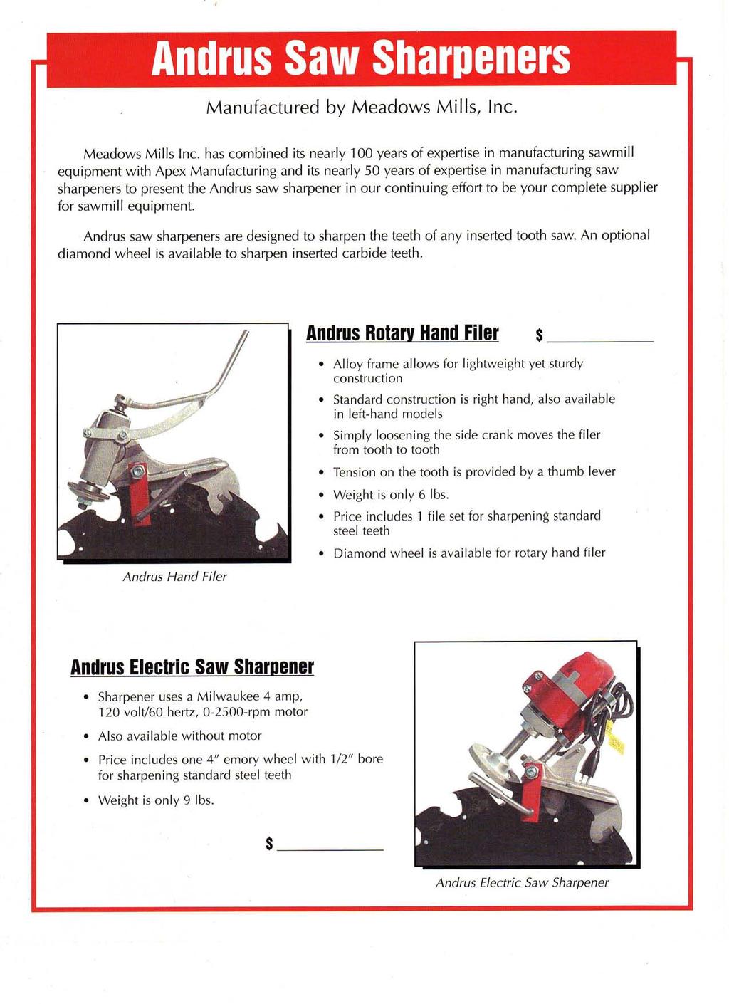
1 THE MARK OF QUALITY SINCE 1902 OPERATOR S INSTRUCTIONS AND PARTS LIST MEADOWS MILLS, INC WEST D STREET PO BOX 1288 NORTH WILKESBORO, NC TOLL FREE: TELEPHONE: FAX: sales@meadowsmills.com WEBSITE:
2 Operating Instructions for the Andrus Electric Saw Sharpener Unpacking your Andrus Saw Sharpener: In reference to the band with bearing (Q), ensure that the nuts (H) holding the hex cap screws (G) are tight. If the band with bearing (Q) is tight this will ensure that the motor remains firmly in place. Using a flat head screwdriver and 7/16 wrench, advance the five adjustment screws (I) on the side of the filer frame (R) to an even depth of ¼. Using your 7/16 wrench tighten nut (H) against the filer frame (R) while holding the screw (I) with your screwdriver. Ensure that the arbor (C) is firmly tightened against the washer (B). Next place the emery wheel (D) on the threaded shaft of the arbor (C), then place the washer (E) on the shaft, and finally finger tighten the nut (F) against the washer (E). The emery wheel (D) should be installed with the label facing the motor. Tighten the jam nut (F), which is found at the end of the arbor (C), firmly against the washer (E) to insure that the emery wheel (D) is held in place properly. The brass bearing (Q1) should be greased prior to operation. The zerk (Q2) can be found on the side of the band with bearing (Q). Aligning your Andrus Saw Sharpener: Place the saw sharpener on the saw so that the flat steel slide (S), located on the under side of the lip on the filer frame (R), rests on at least 2 teeth. The flat steel slide (S) should rest on at least 2 teeth for proper support and balance. The side block (Z) should be adjusted so that the side crank (AA) tightens on a shoulder of the saw. Tighten the side crank (AA) against the shoulder of the saw. Adjust the depth of the five adjustment screws (I) on the side of the filer frame (R) until the filer frame is level on the tooth. The filer frame must be level from side to side to ensure proper operation of the Andrus Saw Sharpener. Position the tooth stop (X), which is located under the wing nut (U) on the filer frame (R), so that the stop rests firmly against the base of the shank. Loosen the set screw on both of the set collars (P). Grasping the grip of the motor, slide the band with bearing (Q) up the shaft (N) until the emery wheel (D) is contacts the tooth. Hold the motor firmly against the tooth.
3 Loosen the nut (J) that holds the eccentric (L), the eccentric frame (M), and the shaft (N) in place. This allows you to set the angle of the emery wheel (D) to match the face of your tooth. Once the angle is set tighten the nut (J) firmly. Continue to hold the motor against the tooth. The upper set collar (P) may be adjusted downwards until contact is made with the band with bearing (Q). This upper set collar (P) will act as an upper stop for the motor. Tighten the set screw in the upper set collar (P). Lower the motor to leave a 3/8 gap between the emery wheel (D) and the tooth. The bottom set collar (P), located under the band with bearing (Q), should be adjusted upwards until contact is made with the band with bearing (Q). This bottom set collar (P) will act as a lower stop for the motor. Tighten the set screw in the bottom set collar (P). As a final check for the setup of your Andrus Saw Sharpener, loosen the side crank (AA) and remove the Andrus Saw Sharpener from the saw. Using a pen/pencil (not provided) trace the profile of the tooth. Reposition the Andrus Saw Sharpener on the saw. Sharpen the tooth (see instructions Operating your Andrus Saw Sharpener ) that you used as your template. Compare the tooth you sharpened to your template to ensure that the filer is setup properly. Operating your Andrus Saw Sharpener: Once you have properly adjusted your Andrus Saw Sharpener to fit your saw, you are ready to file. 1. Depress the trigger on the motor to start the emery wheel. Slowly pull the motor up the shaft (N) until the emery wheel (D) contacts the tooth. Please remember to bring emery wheel (D) into contact with the tooth slowly to ensure a clean evenly sharpened tooth. To move to the next tooth loosen the side crank (AA) and reposition your Andrus Saw Sharpener to the next tooth. Then follow the above instructions (1). Please Remember Lock out power supply to the saw arbor prior to setting up or operating the saw sharpener. As with all pieces of machinery safety glasses should be worn at all times. Also, at no point while the emery wheel is in motion should you attempt to touch the emery wheel with your fingers, hand, or any foreign object. The initial setup is more accurate if it is performed on a tooth with little or no wear. The Andrus Saw Sharpener should be setup perfectly square to ensure the best job of sharpening your teeth.
4
5 ANDRUS ELECTRIC SHARPENER COMPLETE ANDRUS ELECTRIC SHARPENER COMPLETE A MOTOR - ELECTRIC FILER ANDRUS ELECTRIC SHARPENER W/ ARBOR - LESS MOTOR B A WASHER - AIR & ELEC. MOTOR ( C ARBOR - ELECTRIC & AIR FILER D EMORY WHEEL - ELECTRIC & AIR FILERS E SAE FLAT WASHER 9/16" PLN F HEX JAM NUT 1/2" Z G HCS 1/4"-20 x 2-1/4" Z 5 H FIN HEX NUT 1/4-20 Z I RND. HEAD SLOTTED MS 1/4-20 x 1-1/4" J FIN HEX NUT 1/2"-13 Z K USS FLAT WASHER 1/2" Z L ECCENTRIC - ELEC. & AIR FILERS M ECCENTRIC FRAME - ELEC. & AIR FILERS N SLIDE W/ LOCKING COLLARS (INCLUDES PART P) * P SET COLLAR 9/16" W/ SET SCREW O L/W Z 1/2" Q BAND & BEARING - ELEC. SHARPENER, INCLUDES PARTS Q1 & Q2 * Q BC BRONZOIL BUSHING OIL IMPREGNATED * Q ZERK 1/4-28 STR R MAIN FRAME FOR ELEC. & AIR FILERS S FLAT STEELE SLIDE - ELEC., AIR, & HAND FILERS T FLAT HEAD SLOTTED MS x 5/8" Z U WING NUT 1/4-20 V MS NUT Z W ECCENTRIC BOLT - ELEC. & AIR FILERS X STOP - ELEC. & AIR FILERS Y HCS 1/2-13 x 2-1/2" Z 5 Z SIDE BLOCK - ELEC., AIR, & HAND FILERS AA SIDE CRANK - ELEC. & AIR FILERS REFERENCE DWG. ANDRPART01 - ITEM #'S WILL CORRESPOND WITH THE DRAWING Meadows Mills 10/25/2005
6
7
Lumber Smith. Assembly Manual. If you are having problems assembling the saw and need assistance, please contact us at:
 Lumber Smith Assembly Manual If you are having problems assembling the saw and need assistance, please contact us at: 804-577-7398 info@lumbersmith.com 1 Step 1 Safety Carefully read the Owners Manual.
JARVIS. Model BR-3 Blade Reconditioner ... EQUIPMENT TABLE OF
 - Model BR-3 Blade Reconditioner EQUIPMENT SELECTION.......... Ordering No. TABLE OF CONTENTS............................ Page Model BR-3 (100 mm Blade) 115V/60Hz............ 4011003 220V/50Hz............
INSTALLATION OF WELLS SUPER QUICK CHUCK LEFT HAND ON RED WING LATHE
 DENTAL, INC. TECHNICAL BULLETIN Q824-022510 5860 FLYNN CREEK ROAD READ ALL INSTRUCTIONS P.O. BOX 106 BEFORE PROCEEDING COMPTCHE, CALIFORNIA, U.S.A. 95427 SAVE THIS FOR FUTURE REFERENCE www.wellsdental.com
ITEM NO. PART NO DESCRIPTION QTY.
 PUMP MAINTENANCE ITEM NO. PART NO DESCRIPTION QTY. 1 52002 Center Case 1 2 52052 Back End Plate 1 3 52051 Front End Plate 1 4 55090 Octagonal Nut 1 5 53001 Idler Gear 1 6 53002 Drive Gear 1 7 28062 Bushing
INSTRUCTION MANUAL AND PARTS LIST MODEL 14-10
 VERTICAL BAND SAWS INSTRUCTION MANUAL AND PARTS LIST MODEL 1-10 DAKE/PARMA WHEN ORDERING PARTS GIVE COMPLETE SERIAL NUMBER OF MACHINE GIVE PART NUMBER AND NAME GIVE AMOUNT REQUIRED Unless the above data
Maintenance & Parts list for:
 Maintenance & Parts list for: Industrial gun GB 2 Juni 2017 This Maintenance & Parts list for industrial gun is prepared by : Winchester Europe Service V. Parbst & Søn as a comprehensive maintenance guide
This manual will aid in the assembly of the FireBall V90 and FireBall X90. The assembly of both machines will be identical, unless specified.
 This manual will aid in the assembly of the FireBall V90 and FireBall X90. The assembly of both machines will be identical, unless specified. Step #1 Lay all parts out to verify quantities. (2) 2 x 25-1/4
CV1B Sliding Table Installation and Setup Guide
 CV1B Sliding Table Installation and Setup Guide Tech Mark, Inc 7901 Industry Drive North Little Rock, AR 72117 tel (501) 945-9393 fax (501) 945-0312 www.tech-mark.com email: info@tech-mark.com The CV1B
Motorized M3 AX7200 Rotary-Style Gasket Cutter Operating Instructions
 Motorized M3 AX7200 Rotary-Style Gasket Cutter Operating Instructions INTRODUCTION Congratulations! You are the owner of the finest rotary-style gasket cutter in the world. Originally developed and patented
EllisSaw.com. EllisSaw.com P.O. Box Verona, WI
 P.O. Box 9019 Verona, WI 9-019 GENERAL OPERATING & SAFETY INSTRUCTIONS * READ INSTRUCTIONS BEFORE USE * CAUTION: Disconnect power supply cord from power source when doing repair work or changing belt.
southpaw enterprises, inc.
 Eye Bolt Wrap 7001 Store these instructions with the enclosed maintenance checklist in a safe place. You may also access them on our website. this in an accessible location: the must be read and familiar
Page 1. SureMotion Quick-Start Guide: LACPACC_QS 1st Edition - Revision A 03/15/16
 R K C T I Repair Kit Product Compatibility Repair Kit # Linear Actuator Assembly # LACPACC-002 LACPACC-003 LACP-16TxxLP5 (0.5-in lead screw pitch) LACP-16TxxL1 (1-in lead screw pitch) C P I R K 4 ea Flanged
INSTRUCTIONS AND PARTS LIST POWER HAMMER
 INSTRUCTIONS AND PARTS LIST POWER HAMMER DAKE (Division of JSJ) 724 Robbins Road Grand Haven, Michigan 49417 616.842.7110 Phone 800-937-3253 616.842.0859 Fax 800-846-3253 Web: www.dakecorp.com E-mail :
Copyright MLCS 1
 Copyright 2007. MLCS 1 WORKING WITH BOX JOINTS Box joints (AKA "Finger Joints") provide a simple, yet equally effective, alternative to dovetail joinery. In particular, they serve well for applications
LU6X-130 Instructions and Parts List (including LU6X Basic) Operating Instructions
 Operating Instructions") LORTONE LU6X-130 Item # 061-092 LU6X Basic Item # 061-090 LU6X-130 Instructions and Parts List (including LU6X Basic) Operating Instructions Introduction The LU6X is one the most versatile pieces of equipment
LORTONE LU6X-130 Item # 061-092 LU6X Basic Item # 061-090 LU6X-130 Instructions and Parts List (including LU6X Basic) Operating Instructions Introduction The LU6X is one the most versatile pieces of equipment
AndyMark DART 12.
 AndyMark DART 12 Part Number Description QTY These Parts Are Pre-Assembled by AndyMark am-0031 Bearing, 3/16"ID (R3) 1 am-0209 Bearing, 3/8"ID 1614ZZ 2 am-1028 Screw, #10-32x3/8 Pan Head Philips 8 am-1121
GlideRite Retractable Cover System For Hot Spot Spas (SE & SLX only)
") List of Contents Quantity Description 12 #10 x 1 ½ Flat Head Phillips Screw (see pg. 2) 2 #10 x ½ Pan Head Phillips Screw (see pg. 2) 8 ¼ x 2 ½ Lag Bolt (see pg. 2) 7 ¼ 20 x 5 / 8 Hex Head Bolt (see pg.
List of Contents Quantity Description 12 #10 x 1 ½ Flat Head Phillips Screw (see pg. 2) 2 #10 x ½ Pan Head Phillips Screw (see pg. 2) 8 ¼ x 2 ½ Lag Bolt (see pg. 2) 7 ¼ 20 x 5 / 8 Hex Head Bolt (see pg.
Due to possible damage in shipping, the vertical stop assembly has been removed from this machine.
 Due to possible damage in shipping, the vertical stop assembly has been removed from this machine. To assemble, insert the threaded rod through the shroud opening in the top of the machine. Start the four
GlideRite Retractable Cover System For HotSpring & Tiger River Spas (except Classic & pre-2000 Landmark Spas)
") List of Contents Quantity Description 12 #10 x 1 ½ Flat Head Phillips Screw (see pg. 2) 2 #10 x ½ Pan Head Phillips Screw (see pg. 2) 8 ¼ x 2 ½ Lag Bolt (see pg. 2) 7 ¼ 20 x 5 / 8 Hex Head Bolt (see pg.
List of Contents Quantity Description 12 #10 x 1 ½ Flat Head Phillips Screw (see pg. 2) 2 #10 x ½ Pan Head Phillips Screw (see pg. 2) 8 ¼ x 2 ½ Lag Bolt (see pg. 2) 7 ¼ 20 x 5 / 8 Hex Head Bolt (see pg.
COYOTE ENTERPRISES, INC. RIMLOC BLAST WHEEL MAINTENANCE & ASSEMBLY MANUAL
 COYOTE ENTERPRISES, INC. RIMLOC BLAST WHEEL MAINTENANCE & ASSEMBLY MANUAL Parts & Machinery for the Abrasive Blast Industry 27301 East 121st Street Coweta, Oklahoma 74429 (918) 486-8411 Fax (918) 486-8412
Gared Pro-S Portable Backstop
 Models: 9616 & 9618 Installation, Operation and Maintenance Instructions Please read all instructions before attempting installation or operation of these units SAVE THESE INSTRUCTIONS FOR FUTURE USE PUBLICATION
Horizontal and Vertical. Metal Cutting Band Saw MODEL: BS-115
 Horizontal and Vertical Metal Cutting Band Saw MODEL: BS-5 SAFETY. Know your band saw. Read the operator s Manual carefully. Learn the operations, applications and limitation.. Use recommended accessories.
BABY WOLF LOOM. Assembly Instructions for Knocked-Down Looms
 BABY WOLF LOOM Assembly Instructions for Knocked-Down Looms BEFORE YOU BEGIN Please read through the directions before beginning to assemble your loom. Unpack the loom parts carefully. Do not throw away
Metroboard Pulley Replacement Procedure
 Metroboard Pulley Replacement Procedure 1) Remove the two transmission cover screws (1/8 allen driver). Then remove the transmission cover. Note there is a split lock washer and flat washer as well, so
MODEL T28173/T28174 ROLLER TABLES INSTRUCTIONS
 MODEL T28173/T28174 ROLLER TABLES INSTRUCTIONS FOR MODELS MFD. SINCE 10/17 For questions or help with this product contact Tech Support at (570) 546-9663 or techsupport@grizzly.com Rails Rollers Reversible
MODEL RA-2500N RADIAL ARM SAW
 1 6130089 HEX. NUT (L.H.T.) W5/8"-18UNF 2.18 2 6900549 WASHER 1.78 3 6080529 ARBOR COLLAR 31.02 4 6760117 OILLESS METAL 1.57 5 9270612 CLAMP SCREW M6 X 12 0.19 6 9220625 HEX. SOCKET HEAD BOLT M6 X 25 0.22
For additional assistance call
 The following pages will help guide you through the process of assembling your new 48 custom prize wheel. Choose an assembly area with plenty of room to lay your pieces on the floor and also a bench or
ESA-300 Full Breakout
 Interior View 0 Installation Instructions For use with ESA II Controler DORMA AUTOMATICS, Inc. 94 Sherwood Drive Toll-Free: 877-67-6 DL844-00 Lake Bluff, IL 60044 Fax: 877-4-7999 Rev. /07 Tools Required:
INSTALLATION OF WELLS SUPER QUICK CHUCK LEFT HAND ON BALDOR LATHE
 DENTAL, INC. TECHNICAL BULLETIN Q832-022510 5860 FLYNN CREEK ROAD READ ALL INSTRUCTIONS P.O. BOX 106 BEFORE PROCEEDING COMPTCHE, CALIFORNIA, U.S.A. 95427 SAVE THIS FOR FUTURE REFERENCE THIS PRODUCT IS
Small Block Ford. 289 / 302 / 351W / 5.0 Installation Manual For Systems with A/C #13600 / #13620
 Small Block Ford 289 / 302 / 351W / 5.0 Installation Manual For Systems with A/C #13600 / #13620 Billet Specialties, Inc. 500 Shawmut Avenue. La Grange, Illinois 60526 Tech Line (708) 588-0505 Fax (708)
MODEL T10815 GRINDING ATTACHMENTS INSTRUCTIONS
 MODEL T10815 GRINDING ATTACHMENTS INSTRUCTIONS For questions or help with this product contact Tech Support at (570) 546-9663 or techsupport@grizzly.com Introduction Designed to work exclusively with the
OPERATION & MAINTENANCE MANUAL
 OPERATION & MAINTENANCE MANUAL AUTOMATIC PECAN CRACKER Food Processing Equipment and Machinery Specializing in the Pecan Industry Mailing: PO Box 817, Mansfield, Louisiana 71052 Located: 280 Independence
The DeltaGrip System. Safety and Operating Instructions. Trigger. Air Supply Connection. Handle Assembly. Air Line Assembly.
 The DeltaGrip System Safety and Operating Instructions Trigger Air Supply Connection Handle Assembly Air Line Assembly Punch Die Pneumatic Diaphragm Assembly Shackle, Pin & Jam Nut Jaw Frame Shoulder Screw
HQ Pole Upgrade Kit for HQ Adjustable Table and HQ QuilTable Assembly Instructions 1
 HQ Pole Upgrade Kit for HQ Adjustable Table and HQ QuilTable Assembly Instructions QF09775 The pole upgrade kit can be used with or without the QF09700 HQ Precison-Glide track upgrade kit. What s Included
Geology, Prospectors, Mining, Metallurgy, Assaying, Environmental, Geotechnical
 LEGEND INC. Geology, Prospectors, Mining, Metallurgy, Assaying, Environmental, Geotechnical 988 Packer Way Sparks, NV 89431 Tel: (786) 786-3003 Fax: (775) 786-3613 Email: info@lmine.com Web: www.lmine.com
MODELS 49 RA 49 RAZ 49 RAC
 General Safety and Maintenance Manual MODEL grinder featuring a rear exhaust. Model Number Exhaust Direction REAR Throttle Type (L) Lever or (K) Safety Lever Speed 12000 to 14000 R.P.M (13500rpm is standard)
Cut-True 16M Manual Paper Cutter
 Cut-True 16M Manual Paper Cutter 2/2013 OPERATOR MANUAL FIRST EDITION TABLE OF CONTENTS TOPIC PAGE Specifications 1 Safety Guidelines 1 Assembly 2 Overview 3 Description of Equipment Parts 3-4 Operation
Fig Remove chain cover plate bolts. Fig Remove hammer member. Fig Loosen set screws at base of 12-tooth sprocket.
 Fig. 17.2. Remove chain cover plate bolts. Fig. 17.1. Remove hammer member. Fig. 17.3. Remove chain cover plate. Fig. 17.4. Loosen set screws at base of 12-tooth sprocket. Page 61 Fig. 17.5. Remove socket
WOLF PUP LOOM TM & WOLF PUP LT LOOM TM
 WOLF PUP LOOM TM & WOLF PUP LT LOOM TM Assembly Instructions FL3000 FL3006 FL3009 WOLF PUP WOLF PUP LT Find out more at schachtspindle.com Schacht Spindle Company 6101 Ben Place Boulder, CO 80301 p. 303.442.3212
Owner s Manual AE PLUG AERATOR MANUFACTURING QUALITY LAWN CARE EQUIPMENT SINCE Made In CHINA REV
 MANUFACTURING QUALITY LAWN CARE EQUIPMENT SINCE 1945 Owner s Manual AE-48 48 PLUG AERATOR IMPORTANT Read and follow all Safety Precautions and Instructions Before Operating this Equipment. Made In CHINA
Adjusting Backlash on Sherline handwheels
 WEAR YOUR SAFETY GLASSES FORESIGHT IS BETTER THAN NO SIGHT READ INSTRUCTIONS BEFORE OPERATING Adjusting Backlash on Sherline handwheels What Is Backlash? Backlash is the amount the handwheel can turn before
Item #28187 EASTWOOD BEAD ROLLER INSTRUCTIONS
 Item #28187 EASTWOOD BEAD ROLLER INSTRUCTIONS The Eastwood Bead Roller is a professional metal fabrication tool for producing strengthening ribs in panels used in creating replacement fl oor pans, fi rewalls,
EXIT DEVICE OPERATION FIRE DOOR LABELS, STRIKES AND FRAME SCREWS FOR INFORMATION CALL OR VISIT RITEDOOR.COM
 RECORD & LABELS WHAT THIS OWNER'S CAN DO FOR YOU It explains exactly how The Rite Door operates. It explains periodic maintenance requirements necessary to assure reliable operation. It explains simple
INSTRUCTION MANUAL. Lathe Duplicator MODEL North Glenn Road, Casper, Wyoming woodworker.com
 140-069LatheDuplictr(1/12) 10/30/06 8:20 AM Page 1 INSTRUCTION MANUAL Lathe Duplicator MODEL 140-069 1108 North Glenn Road, Casper, Wyoming 82601 1-800-645-9292 woodworker.com 140-069LatheDuplictr(1/12)
MODEL 83 Pail Handler
 MORSE MFG. CO., INC. 727 West Manlius Street P.O. Box 518 East Syracuse, NY 13057-0518 Phone: 315-437-8475 Fax: 315-437-1029 Email: service@morsemfgco.com Website: www.morsemfgco.com COPYRIGHT 2005 MORSE
INSTRUCTION BOOK AND PARTS LIST
 Rag Cutter MODEL WE WARNING This machine is equipped with a very sharp knife. Keep hands, arms, and hair away from the knife area at all times. Misuse of this machine or failure to follow all safety instructions
PHG-1000X. Owner s Manual HOME GYM
 HOME GYM Owner s Manual WWW.BODYSOLID.COM THERE IS A RISK ASSUMED BY INDIVIDUALS WHO USE THIS TYPE OF EQUIPMENT. TO MINIMIZE RISK, YOU MUST FOLLOW THESE RULES:! " # $ % & ' ( ) * + ' (, ' " -. *, * ) )
Operating, Servicing, and Safety Manual Model " Foot Shear CAUTION: Read and Understand
 Operating, Servicing, and Safety Manual Model 3000 52" Foot Shear CAUTION: Read and Understand These Operating, Servicing, and Safety Instructions, Before Using This Machine. SAFETY The purpose of the
Assemble and Adjustment Instructions and Flex Balance Beam and Crank Balance Beam
 Sales & Service sasportonline.com Head Office 135 Forestview Road P.O. Box 40 Orillia, Ontario Canada L3V 6H9 Toll Free (800) 563-6479 Phone (705) 325-2274 Fax (705) 325-1485 USA Office 7879 Will Rogers
JARVIS. Model Buster IV Forequarter Beef Splitting Band Saw Installation Instructions... 9 TABLE OF EQUIPMENT
 Beef Splitting Band Saw EQUIPMENT SELECTION............. Ordering No. TABLE OF CONTENTS......................... Page Buster IV Forequarter Saw.... 4006058 Spring Balancer............. 4042023 Blade......................
MODEL H " BYRD SHELIX CUTTERHEAD INSTRUCTIONS
 MODEL H9291 12" BYRD SHELIX CUTTERHEAD INSTRUCTIONS The Model H9291 12" Byrd Shelix cutterhead is designed to replace the straight-knife cutterhead on the Grizzly jointer Model G0609. The total procedure
SERVICE MANUAL AND PARTSLIST
 SERVICE MANUAL AND PARTSLIST Next 20 CONTENTS WHAT TO DO WHEN... 1~3 SERVICE ACCESS FACE COVER... 4 TOP COVER... 4 BASE COVER... 5 REAR COVER... 6 FRONT COVER... 7 MECHANICAL ADJUSTMENT NEEDLE THREAD TENSION...
Tuf-Lite Fans 3000B Series Hub (For B, C, D & W Blades)
") Tuf-Lite Fans 3000B Series Hub (For B, C, D & W Blades) INSTALLATION MANUAL Hudson Tuf-Lite fan blades Adjustable Pitch Fan Assembly 5 through 16 Diameter (Note: 15 & 16, W-Blade only) Hudson Tuf'Lite
Tuf-Lite Fans 3000B Series Hub (For B, C, D & W Blades) INSTALLATION MANUAL Hudson Tuf-Lite fan blades Adjustable Pitch Fan Assembly 5 through 16 Diameter (Note: 15 & 16, W-Blade only) Hudson Tuf'Lite
Installing CNC Stepper Motor Mounts On A Sherline Mill
 Installing CNC Stepper Motor Mounts On A Sherline Mill P/N 6700 (6710 Metric) 5000/5100/5400/5410 Mills P/N 6705 (6715 Metric) 2000/2010 Mills USING THE TEMPLATE BLOCKS TO LOCATE NEW MOUNTING HOLES FOR
Side Winder R o u t e r L i f t.
 Woodpeckers PRECISION WOODWORKING TOOLS Side Winder R o u t e r L i f t. INSTALLATION INSTRUCTIONS The wrench handle must be pointing left in order to fully insert or remove it. Lift Wrench Once fully
STENCIL MACHINE OPERATION uline.com H-259, H-347 H-408 CUTTING THE OIL BOARD INSERTING THE OIL BOARD
 H-259, H-347 H-408 π STENCIL MACHINE 1-800-295-5510 uline.com OPERATION NOTE: No assembly is necessary after you unpack your machine. INSERTING THE OIL BOARD 1. Move the release lever to the right. This
JARVIS. Model Buster V Loin Drop Beef Loin Dropping Saw
 Beef Loin Dropping Saw EQUIPMENT SELECTION... Buster V Loin Drop Saw Ordering No. 230V, 60Hz Model... 4006051 460V, 60Hz Model... 4006060 575V, 60Hz Model... 4006087 Spring Balancer... 4042038 Blade (133
C a r r i a g e A s s e m b l y R e p l a c e m e n t
 E1 TF-CR C a r r i a g e A s s e m b l y R e p l a c e m e n t October 2007 Software Version 5.0 and higher IMPORTANT! TigerStop must be enabled with a code that must be obtained from TigerStop Customer
Service Manual. 600 Series Box Frame Steering Shaft and Segment Gear Servicing
 Service Manual 600 Series Box Frame (These procedures are appropriate for box frame tractors produced after November 2002) IMPORTANT: READ SAFETY RULES AND INSTRUCTIONS CAREFULLY This Service Manual is
Sliding Crosscut Table installation guide
 Sliding Crosscut Table installation guide model tsa-sa48 A Note About Color Variations Among Anodized Aluminum Components Congratulations on the purchase of this SawStop Sliding Crosscut Table. We at SawStop
Wheeler Rex Ashtabula, Ohio Tel: Fax:
 Wheeler Rex Ashtabula, Ohio Tel: 800 321 7950 Fax: 440 992 2925 wheeler@wheelerrex.com www.wheelerrex.com December 2012 There are three different types of shell cutters. Nominal Hole Size Part No. 4" 3395
Warnings. Description. Prior to Installation Tools Needed
 Warnings Failure to act in accordance with the following may result in death or personal injury. The JT Strong Arm Stabilizer System is intended to eliminate chassis movement in travel trailers and fifth
FM2113PC/FM2114PC SBC Top Mount Alt, w/ A/C & Power Steering
 10) At this time assemble the power steering bracket and pump assembly from the instructions provided with the power steering bracket beginning at step 7. Return to step 10 on this sheet when complete.
30AUTO Speed Lathe Manual
 30AUTO Speed Lathe Manual Standard Features 3/4 HP Motor Air-Collet Closure 1800 RPM, Single Speed Electric Brake Cast Housing 5C Collets 3 Phase / 240 Volts DESCRIPTION: The Crozier Model 30AUTO Automotive
Installing CNC Stepper Motor Mounts On A Sherline Lathe
 Installing CNC Stepper Motor Mounts On A Sherline Lathe P/N 6720 (6725 Metric) 4000/4100/4500/4600 Lathes P/N 6730 (6735 Metric) 4400/4410 Lathe USING THE TEMPLATE BLOCKS TO LOCATE NEW MOUNTING HOLES FOR
SERVICE MANUAL PARTS LIST MODEL: NH40
 SERVICE MANUAL & PARTS LIST MODEL: NH40 CONTENTS What to do when... 1-3 SERVICE ACCESS Face Cover... 4 Bed Cover... 5 Free-arm Cover... 6 Front Cover... 7 Rear Cover... 8 MECHANICAL ADJUSTMENT Presser
Ringblaster Mark IV Maintenance Guide. Version 1.5
 Ringblaster Mark IV Maintenance Guide Version 1.5 WARNING Winchester Industrial Equipment and Loads must be properly stored, handled and maintained for safe and proper function. Mishandling or failure
model tsa-sa48 Sliding Crosscut Table installation guide
 model tsa-sa48 Sliding Crosscut Table installation guide A Note About Color Variations Among Anodized Aluminum Components Congratulations on the purchase of this SawStop Sliding Crosscut Table. We at SawStop
FM2113PC/FM2114PC SBC Top Mount Alt, w/ A/C & Power Steering
 10) At this time assemble the power steering bracket and pump assembly from the instructions provided with the power steering bracket beginning at step 7. Return to step 10 on this sheet when complete.
MINI-LATHE QUICK CHANGE TOOL POST
 MINI-LATHE QUICK CHANGE TOOL POST Cutting and assembly details Machinists should familiarize themselves with the contents of this section before jumping in to the drawings. Many details are described here
V-MOTION LITE USER GUIDE. Rat Rig All rights reserved.
 V-MOTION LITE USER GUIDE Rat Rig 2017. All rights reserved. PACKAGE CONTENTS 1 1x V-Motion Motor 2 1x Belt 3 1x 3mm Hex Key 4 1x AA Battery Pack (for 8x AA batteries)* 5 1x V-Motion Controller 6 2x Knob
MODEL T " HELICAL CUTTERHEAD INSTALLATION INSTRUCTIONS
 MODEL T27696 12" HELICAL CUTTERHEAD INSTALLATION INSTRUCTIONS For questions or help with this product contact Tech Support at (570) 546-9663 or techsupport@grizzly.com Introduction The Model T27696 indexable
MODEL H9565 BALL BEARING GUIDE FOR G0513/G0514 INSTRUCTION SHEET
 MODEL H9565 BALL BEARING GUIDE FOR G0513/G0514 INSTRUCTION SHEET Introduction The Model H9565 replaces the upper and lower Euro-style guides on your G0513 or G0514 Bandsaw. Inventory (Figure 1) A. Upper
PRS Retro Z-Axis Installation
 PRS Retro Z-Axis Installation Page -1- PRS Retro Z-Axis Installation This document is a guide to installing the PRS Retro Z-axis on early ShopBot models. It describes installation for PR models with PK299
OPERATIONS MANUAL. Port-O-Slitter
 Tapco Products Company The World Leader in Specialty Tools for the Professional Port-O-Slitter OPERATIONS MANUAL General instructions, set up, accessories and guide to using your portable precision slitting,
Model 209 Fireback Replacement
 Model 209 Fireback Replacement Please read all the instructions before you begin the procedure. Confirm that you have all the necessary tools and materials. If you have any questions, technical support
MODEL T " PORTABLE BENCHTOP BRAKE INSTRUCTIONS
 MODEL T10052 14" PORTABLE BENCHTOP BRAKE INSTRUCTIONS 1. Overloading this tool can cause injury from flying parts. Do not exceed the machine capacities. 2. Secure bench hand brake to a sturdy surface before
INSTRUCTIONS & PARTS LIST FOR HAND BRAKES
 INSTRUCTIONS & PARTS LIST FOR HAND BRAKES MODELS 144-22, 168-22, 192-22, 120-16, 120-14 When ordering repair parts, please refer to the item number, quantity, name of part, part number and serial number
MODEL 36 Di-Acro Hand Shear
 OPERATOR S MANUAL & INSTRUCTIONS MODEL 36 Di-Acro Hand Shear Di-Acro, Incorporated PO Box 9700 Canton, Ohio 44711 3713 Progress Street N.E. Canton, Ohio 44705 330-455-1942 330-455-0220 (fax) Revised 01/02
RECOMMENDED SPARE PARTS FOR NORMAL ONE (1) YEAR OPERATION OF VD CRUSHER
 YEAR OPERATION OF VD CRUSHER") RECOMMENDED SPARE PARTS FOR NORMAL ONE (1) YEAR OPERATION OF VD CRUSHER 2 ea. VD-65 Toggle 2 ea. VD-70A Right Hand Bearing Split Bushing 2 ea. VD-70B Left Hand Bearing Split Bushing 2 ea. VD-82 Plate for
RECOMMENDED SPARE PARTS FOR NORMAL ONE (1) YEAR OPERATION OF VD CRUSHER 2 ea. VD-65 Toggle 2 ea. VD-70A Right Hand Bearing Split Bushing 2 ea. VD-70B Left Hand Bearing Split Bushing 2 ea. VD-82 Plate for
Customer Notice: Congratulations again on your SawStop purchase, and thank you! -SawStop Tualatin, OR
 Customer Notice: Congratulations on the purchase of this Sliding Crosscut Attachment. As the owner of a SawStop saw, you are familiar with our high standards for quality, fit and finish. Different from
INSPECTION AND CORRECTION OF BELLHOUSING TO CRANKSHAFT ALIGNMENT
 INSPECTION AND CORRECTION OF BELLHOUSING TO CRANKSHAFT ALIGNMENT BACKGROUND Proper alignment of the transmission input shaft to the crankshaft centerline is required in order to achieve the best results
Lab Style Table Frame Part No Assembly Guide Automation Technology
 Ergonomic Workstations Lab Style Table Frame Part No. 8 0 Assembly Guide 7 90 70 Automation Technology SPECIFICATIONS Lab style frame part number... 80 Height... 70 mm (8.") Width... 90 mm (.7") Depth...
meaden New Generation Tooling & Operations Manual
 06-19-01 New Generation Tooling & Operations Manual 210 West 83rd Street Burr Ridge, Illinois 60527 Telephone: 630/655-0888 FAX: 630/655-3012 www.printing.com INTRODUCTION Table of Contents I. ENGAGEMENT
THIS KIT INCLUDES: 8 M8-1.25X40MM BOLTS WITH WASHERS 8 M8-1.25X30MM BOLTS WITH WASHERS RIGHT AND LEFT HINGE
 Sal es@lambodoorscanada. com 2407A Kal adarave,ottawa,on K1V 8B9 THIS KIT INCLUDES: 8 M8-1.25X40MM BOLTS WITH WASHERS 8 M8-1.25X30MM BOLTS WITH WASHERS RIGHT AND LEFT HINGE 2 SHOCKS 565 PSI 2 SHOULDER
General Features. Low Profile. The SMART BOXX stands only 1.5 off of the bed of your truck so cargo space is maximized
 General Features Low Profile. The SMART BOXX stands only 1.5 off of the bed of your truck so cargo space is maximized Two Sizes Short Box :74 L X 47 W X 7 T and Long Box 92 L X 47 W X 7 T All Aluminium
Inventory (Figure 2)
") MODEL T10127 12" SPIRAL CUTTERHEAD INSTRUCTIONS The Model T10127 indexable insert spiral cutterhead is designed to replace the straightknife cutterhead from the Grizzly jointer Model G0609. The total procedure
MODEL T10127 12" SPIRAL CUTTERHEAD INSTRUCTIONS The Model T10127 indexable insert spiral cutterhead is designed to replace the straightknife cutterhead from the Grizzly jointer Model G0609. The total procedure
Chain Drive Vise. Installation Instructions. (revised 05/04/2016)
") Chain Drive Vise Installation Instructions (revised 05/04/2016) Lie-Nielsen Chain Drive Vise Instructions Table of Contents page About Your Chain Drive Vise 3 Parts List 4 Exploded Parts Diagram 5 step
Chain Drive Vise Installation Instructions (revised 05/04/2016) Lie-Nielsen Chain Drive Vise Instructions Table of Contents page About Your Chain Drive Vise 3 Parts List 4 Exploded Parts Diagram 5 step
MODEL T /2-TON ARBOR PRESS INSTRUCTIONS
 MODEL T27033 1/2-TON ARBOR PRESS INSTRUCTIONS For questions or help with this product contact Tech Support at (570) 546-9663 or techsupport@grizzly.com Introduction This arbor press is designed to perform
Cam Handle Service Guide
 Cam Handle Service Guide Page 2. Introduction Page 3. Troubleshooting guide Page 4-5. Adjusting the clamp force Page 6-7. Disassembling, greasing and replacing components Page 8-9. Replacing the post bearings
CORVETTE CORVETTE REV: Made in USA U.S. PATENT #6,808,223; #6,845,547; #7,140,075; #7,059,655 and other patents pending.
 CORVETTE 2005-2006 CORVETTE 2005-2007 REV: 7-2-07 Made in USA U.S. PATENT #6,808,223; #6,845,547; #7,140,075; #7,059,655 and other patents pending. Page 1 of 12 CORVETTE C6 2005-2007 THIS KIT INCLUDES:
MODEL H-9 HEAVY DUTY BENCH-TYPE UNDERCUTTER INSTRUCTIONS
 MODEL H-9 HEAVY DUTY BENCH-TYPE UNDERCUTTER INSTRUCTIONS CAPACITY: Between centers - 32" long x 12" diameter. Between roller V- supports - 35" long x 17" diameter. Maximum armature weight - 200 lbs. SAW
#916 CLASSIC 16 GUN CABINET ASSEMBLY INSTRUCTIONS
 Thank you for purchasing this quality product. A list of PARTS and INSTRUCTIONS is included to assist you. Unpack and identify all parts included on the Parts List and Hardware List. If parts are missing,
HOLE CUTTER SHARPENER ASSEMBLY & SERVICE MANUAL
 HOLE CUTTER SHARPENER ASSEMBLY & SERVICE MANUAL WARNING You must thoroughly read and understand this manual before operating the equipment, paying particular attention to the Warning & Safety instructions.
INSTALLATION INSTRUCTIONS HEAVY DUTY TILT WALL MOUNT Model: PPH-2000
 INSTALLATION INSTRUCTIONS HEAVY DUTY TILT WALL MOUNT Model: PPH-2000 Specifications: Accomodates Akira and Orion 84" displays without interface bracket; accomodates other large flat panel displays with
Technical Training USG Saw Chain Grinder
 Technical Training USG Saw Chain Grinder 1 USG HOS The STIHL USG Universal Sharpener will sharpen all types of saw chain. This is by far the most versatile and accurate machine of its type on the market.
JARVIS. Model Brisket Scissor EQUIPMENT... TABLE OF
 Model 423-17 Brisket Scissor EQUIPMENT SELECTION... Ordering No. TABLE OF CONTENTS... Page Model 423--17... 4037003 Air Filter / Regulator / Lubricator 3022003 Air Hose Assembly... 3059018 Balancer...
400A 40113V, 401A 40120V, & 401AL 40120VL ALUMINUM VERTICAL 4000 LB LIFT INCLUDES SCREW LEG ASSEMBLY INSTRUCTIONS
 12/11/07 PAGE 1 OF 12 400A 40113V, 401A 40120V, & 401AL 40120VL ALUMINUM VERTICAL 4000 LB LIFT INCLUDES SCREW LEG ASSEMBLY INSTRUCTIONS Thank you for purchasing our product! *Please read these instructions
STARTING SERIAL NUMBER PARTS LIST FOR. Wellsaw MODEL 600 METAL CUTTING BAND SAW
 STARTING SERIAL NUMBER 11075 PARTS LIST FOR Wellsaw MODEL 600 METAL CUTTING BAND SAW Wellsaw 2829 N. Burdick, Kalamazoo, MI 49004 Phone: 269-345-1132 Fax: 269-345-0095 Rev 171005 INSTALLATION, OPERATION
Grizzly Drill Press SOP
 Grizzly Drill Press SOP Drill Press is wired to run on 0V. Drill Press has a built in light with a ON/OFF switch. Never hold a workpiece by hand while drilling. Clamp it down or hold it in a vice. Never