MODEL H-9 HEAVY DUTY BENCH-TYPE UNDERCUTTER INSTRUCTIONS
|
|
|
- Marian Stewart
- 5 years ago
- Views:
Transcription
1 MODEL H-9 HEAVY DUTY BENCH-TYPE UNDERCUTTER INSTRUCTIONS CAPACITY: Between centers - 32" long x 12" diameter. Between roller V- supports - 35" long x 17" diameter. Maximum armature weight lbs. SAW SPINDLES: 5/16" Cutter Arbor for 7/8" x 5/16" or 1" x 5/16" saws or V-Cutters. 3/16" Cutter Arbor for 1/2" x 3/16" saws or V-Cutters. SPINDLE SPEEDS: H.S.S. - For high speed steel saws or V-Cutters the pulleys on both the motor and the spindle should be the same 2" diameter. CARBIDE - For carbide saws or V-Cutters, the larger 4" diameter pulley should be used on the motor and a 2 diameter pulley on the spindle. Both pulleys and belts are supplied. Saws and V-Cutters High-Speed Steel O.D. I.D. Catalog Number 16-HS Saws 1/2 3/16 HSMS16 17-VHS Cutters 1/2 3/16 HSMSV17 75-HS Saws 7/8 5/16 HSMS75 75-VHS Cutters 7/8 5/16 HSMSV75 85-HS Saws 1 5/16 HSMS85 85-VHS Cutters 1 5/16 HSMSV85 Tungsten-Carbide O.D. I.D. Catalog Number 16-TC Saws 1/2 3/16 TUNS16 17-VTC Cutters 1/2 3/16 TUNSV17 75-TC Saws 7/8 5/16 TUNS75 75-VTC Cutters 7/8 5/16 TUNSV75 85-TC Saws 1 5/16 TUNS85 85-VTC Cutters 1 5/16 TUNSV85 For further specifications see pages 14 and 15 of Martindale Undercutters Catalog.
2 INSTRUCTIONS: INITIAL ASSEMBLY: 1. Reverse the Depth Adjusting Handwheel on the shaft and secure in place. 2. Attach the lamp to the motor mounting bracket platform. 3. Reverse the Center Adjusting Handwheel on the end of the Horizontal Adjusting Screw and secure in place. 4. Place magnetic-grip Eyeshield on front Roller-V-Support. TO CHANGE SAW SPINDLE: 1. Loosen 2 set screws on Arbor Support and slide support off. 2. Loosen 2 set screws in Spindle Block just enough to allow rotation of the 1" diameter Overarm Shaft. 3. Slide the new Arbor Support on and rotate the Overarm Shaft until the flat aligns with the set screws. 4. Tighten the set screws in the Arbor Support and then the set screws in the Spindle Block. OPERATION: SET-UP: 1. Loosen the Tee Bolt and tilt the cutting head assembly back to make loading and unloading armatures easier. 2. Adjust the position of the Rear Support for the length of the armature and adjust the Center Jack for light tension on the table. 3. Mount the armature on the Roller-V-Supports. 4. Bring the cutting head assembly back into its normal operating position and tighten the Tee Bolt. Adjust the Carriage Jack for light contact on the table and secure it with the jam nut. 5. Level the commutator of the armature to be parallel with the Slide Rods using the Height Adjustment Knobs and lock in place with the Roller Height Knobs.
3 6. The Saw Spindle rotates in a counter-clockwise direction (when facing saw end of spindle). Mount saw so teeth on bottom rotate toward the operator. 7. Adjust the Carriage Stop Collars so as to prevent the saw from hitting the riser but also to allow a slight overtravel at the front. 8. Align the saw with a mica strip at the front of the travel and push the cutting head back to the riser. Adjust the skew knob to align the mica under the saw at the rear. Re-check for alignment for the entire trav el then when adjusted correctly, lock the skew adjustment. 9. To set the depth of the cut, align the saw with the mica and gently lower the cutter assembly into the mica. The Depth Adjusting Wheel will raise or lower the cutting head assembly approximately 1/16" for one complete turn of the wheel. After adjusting, lock the adjustment in place with the thumb screw. Note: To cut small diameter commutators when using the centers, it may be necessary to remove the two 3/8" thick clamp plates on the vertical adjustment rods. 10. To undercut - Start at the riser. Gently lower the saw into the mica and pull the carriage towards the operator. Release the handle to disen gage the saw and push the carriage back to the riser. The cutter assembly is spring-loaded to lift out of the slot on the return stroke. 11. Align the saw with the next mica strip and continue undercutting. MAINTENANCE: Keep the Carriage Slide Rods clean. Apply a drop of oil to the Saw Arbor Bushings periodically.
4
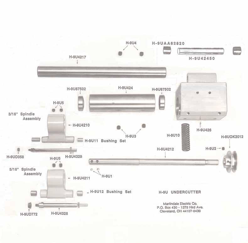
5 MODEL H-9 HEAVY DUTY BENCH-TYPE U/C PARTS LIST QTY. DESCRIPTIION PART NO. 1 Housing, Spindle, Drive H-9U424 1 Block, Spindle H-9U426 2 Screw, Cone, Slotted H-9U427 1 Block, Outboard Bearing, 3/16 H-9U Block, Outboard Bearing, 5/16 H-9U Spindle, Drive H-9U Block, Pivot H-9U Arm, Over H-9U Spindle, Saw, 5/16 H-9U Nut, Saw Retaining, 5/16 H-9UD772 1 Spindle, Saw, 3/16 H-9U Nut, Saw Retaining, 3/16 H-9UD358 2 Screw, 1/4-28x3/16, Set, Hollow Hd. H-9U1 1 Screw, 1/4-20 x 5/16, Set, Hollow Hd. H-9U2 2 Screw, 5/16-18 x 1/4, Set, Hollow Hd. H-9U3 2 Screw, 5/16-18 x 5/16, Set, Hollow Hd. H-9U4 2 Screw, 3/8-16 x 5/16, Set, Hollow Hd. H-9U5 2 Nut, 1/2-13, Jam H-9U8 4 Plug, Brass H-9U9 1 Spring H-9U10 1 Bushing Set H-9U11 1 Bushing Set H-9U12 2 Bearing H-9U Pulley H-9UOK2012
6
HA-2 INDUSTRIAL UNDERCUTTER INSTRUCTIONS. Caution!
 HA-2 INDUSTRIAL UNDERCUTTER INSTRUCTIONS Caution! The Outrigger Assembly MUST be supported and the Pawl Finger, on the Safety Pawl, engaged in the rack BEFORE loosening the two (2) Clamping Bolts. Personal
25-200H. 12 Planer / Jointer. with Helical Cutterhead. Parts List.
 25-200H 12 Planer / Jointer with Helical Cutterhead 4001824 Parts List www.rikontools.com CABINET ASSEMBLY PARTS EXPLOSION & PARTS LIST KEY NO. DESCRIPTION KEY NO. DESCRIPTION 1 Pan Head Screw M6x12 P25-200H-1
RYOBI 10 in. TABLE SAW - MODEL NO. BT3000
 FOR MITER TABLE ASSEMBLY, REFER TO FIGURE 0 RYOBI 0 in. TABLE SAW - MODEL NO. BT000 FIGURE 5: 0 in. TABLE SAW FOR BLADE GUARD ASSEMBLY, REFER TO FIGURE FOR RIP FENCE ASSEMBLY, REFER TO FIGURE FOR MOTOR
Parts Catalog. S-Series Slicer Smart Manual SG13. Model:
 , 07 99507 ECN 065 Parts Catalog S-Series Slicer Smart Manual Model: SG SG 0/0/07 Rev. G IMPORTANT! TO EXPEDITE SHIPMENT OF PARTS, ALWAYS SPECIFY MODEL, REV, PART NUMBER, AND SERIAL NUMBER OF UNIT. GLOBE
MODEL H " BYRD SHELIX CUTTERHEAD INSTRUCTIONS
 MODEL H9291 12" BYRD SHELIX CUTTERHEAD INSTRUCTIONS The Model H9291 12" Byrd Shelix cutterhead is designed to replace the straight-knife cutterhead on the Grizzly jointer Model G0609. The total procedure
Inventory (Figure 2)
") MODEL T10127 12" SPIRAL CUTTERHEAD INSTRUCTIONS The Model T10127 indexable insert spiral cutterhead is designed to replace the straightknife cutterhead from the Grizzly jointer Model G0609. The total procedure
MODEL T10127 12" SPIRAL CUTTERHEAD INSTRUCTIONS The Model T10127 indexable insert spiral cutterhead is designed to replace the straightknife cutterhead from the Grizzly jointer Model G0609. The total procedure
Student, Department of Mechanical Engineering, Knowledge Institute of Technology, Salem, Tamilnadu (1,3)
") International Journal of Scientific & Engineering Research, Volume 7, Issue 5, May-2016 11 Combined Drilling and Tapping Machine by using Cone Mechanism N.VENKATESH 1, G.THULASIMANI 2, S.NAVEENKUMAR 3,
International Journal of Scientific & Engineering Research, Volume 7, Issue 5, May-2016 11 Combined Drilling and Tapping Machine by using Cone Mechanism N.VENKATESH 1, G.THULASIMANI 2, S.NAVEENKUMAR 3,
SPIDA SAW OPERATIONS MANUAL
 SPIDA SAW OPERATIONS MANUAL CM SERIAL NUMBER. OCTOBER 2000 CONTENTS Page description 1.) Contents 2.) Safety First 3.) CM Overview 4.) CM Specifications 5.) CM Installation 6.) CM Operation Setting the
RYOBI 10 IN (254 MM) TABLE SAW MODEL NO. BT REPAIR SHEET
 TABLE SAW MODEL NO. BT REPAIR SHEET") RYOBI 0 IN (2 MM) TABLE SAW MODEL NO. BT00- REPAIR SHEET 2 RYOBI 0 in. (2 mm) TABLE SAW - MODEL NO. BT00- FOR MITER TABLE ASSEMBLY, REFER TO FIGURE B FOR BLADE GUARD ASSEMBLY, REFER TO FIGURE E FOR RIP
RYOBI 0 IN (2 MM) TABLE SAW MODEL NO. BT00- REPAIR SHEET 2 RYOBI 0 in. (2 mm) TABLE SAW - MODEL NO. BT00- FOR MITER TABLE ASSEMBLY, REFER TO FIGURE B FOR BLADE GUARD ASSEMBLY, REFER TO FIGURE E FOR RIP
Parts Catalog. S-Series Slicer Manual Frozen Option S13. Model:
 , 07 995 ECN 08 Parts Catalog S S-Series Slicer Manual Frozen Option Model: S 05/0/07 Rev. G IMPORTANT! TO EXPEDITE SHIPMENT OF PARTS, ALWAYS SPECIFY MODEL, REV, PART NUMBER, AND SERIAL NUMBER OF UNIT.
Operating Instructions and Parts Manual. 10 x 16 Horizontal Band Saw Models J-7020, J-7040
 Operating Instructions and Parts Manual 10 x 16 Horizontal Band Saw Models J-7020, J-7040 JET 427 New Sanford Road LaVergne, Tennessee 37086 Part No. M-414472 Ph.: 800-274-6848 Revision C2 03/2014 www.jettools.com
MODEL T " HELICAL CUTTERHEAD INSTALLATION INSTRUCTIONS
 MODEL T27696 12" HELICAL CUTTERHEAD INSTALLATION INSTRUCTIONS For questions or help with this product contact Tech Support at (570) 546-9663 or techsupport@grizzly.com Introduction The Model T27696 indexable
FBX1104P FBX1104 FBX1106P FBX1106
 FBX1104P FBX1104 FBX1106P FBX1106 Second edition : September 2004 No. 040037 INTRODUCTION Thank you for your purchasing Kansai Special's FBX Series. Read and study this instruction manual carefully before
ABM International, Inc. Navigator Assembly Manual
 ABM International, Inc. 1 1.0: Parts List Tablet (Qty. 1) Tablet mount (Qty. 1) NOTE: Mount may appear and operate different then image below Control Box (Qty. 1) Motor Power Supply (Qty. 1) 2 X-axis motor
Due to possible damage in shipping, the vertical stop assembly has been removed from this machine.
 Due to possible damage in shipping, the vertical stop assembly has been removed from this machine. To assemble, insert the threaded rod through the shroud opening in the top of the machine. Start the four
RYOBI 10 in. (254 mm) TABLE SAW MODEL NO. BT3100 REPAIR SHEET
 TABLE SAW MODEL NO. BT3100 REPAIR SHEET") RYOBI 0 in. (4 mm) TABLE SAW MODEL NO. BT00 REPAIR SHEET FOR MITER TABLE ASSEMBLY, REFER TO FIGURE B FOR BLADE GUARD ASSEMBLY, REFER TO FIGURE E FOR RIP FENCE ASSEMBLY, REFER TO FIGURE C FOR MOTOR ASSEMBLY,
RYOBI 0 in. (4 mm) TABLE SAW MODEL NO. BT00 REPAIR SHEET FOR MITER TABLE ASSEMBLY, REFER TO FIGURE B FOR BLADE GUARD ASSEMBLY, REFER TO FIGURE E FOR RIP FENCE ASSEMBLY, REFER TO FIGURE C FOR MOTOR ASSEMBLY,
BASE, COLUMN, ARM AND TABLE
 SPARE S LIST Item No. 700000 Article No. 84-2265 IMPORTANT INSTRUCTIONS It is most important that the above illustration be studied prior to the assembly of the saw blade and arbor or the assembly of the
Removing the Z-Axis lead screw
 Page 1 of 8 TITLE: Sabre Z-Axis Lead Screw Replacement Procedure Gerber FastFact #: 5048 Supplied by: Gerber Hardware Support Last Modified: June 14, 2007 Summary: Tools used: The following procedure explains
SECTION 9: PARTS. Table Breakdown REF PART # DESCRIPTION REF PART # DESCRIPTION
 SECTION 9: PARTS Table Breakdown 1 2 3 4 5 6 7 8 9 10 11 12 13 14 15 16 17 18 19 20 21 22 23 24 23 25 17 26 27 8 1 P0675001 CAP SCREW M8-1.25 X 30 15 P0675015 SUPPORT BLOCK 2 P0675002 TABLE SUPPORT BLOCK
VARIABLE SPEED WOOD LATHE. Model DB900 INSTRUCTION MANUAL
 VARIABLE SPEED WOOD LATHE Model DB900 INSTRUCTION MANUAL 1007 TABLE OF CONTENTS SECTION...PAGE Technical data.. 1 General safety rules....1-3 Specific safety rules for wood lathe.....3 Electrical information.4
535A. Main Components. Pipe and Bolt Threading Machine. Printed in U.S.A. Ridge Tool Company/Elyria, Ohio, U.S.A.
 Pipe and Bolt Threading Machine A Main Components 0 Screw, Button Head /" - 0 x /" () Washer, Flat /" ()" Top Cover 0 Base Bottom Cover Screw, Pan Head # - x " () Carriage Assembly 0 Front Support Bar
How to program the digital speed display (This is factory set and will only need to be programmed if the unit is replaced)
") How to program the digital speed display (This is factory set and will only need to be programmed if the unit is replaced) 1. Press and hold the set button (top left corner) until the display shows Fun
How to program the digital speed display (This is factory set and will only need to be programmed if the unit is replaced) 1. Press and hold the set button (top left corner) until the display shows Fun
Basic steps to time the Gammill quilting machine s rotary sewing hook
 Basic steps to time the Gammill quilting machine s rotary sewing hook 1.) Turn the machine off and unplug it. 2.) With the needle bar in the raised position, remove the bobbin and bobbin case. 3.) Remove
Tire Chain Kit. Replacing Shear Pins. Weight Kits. Drift Cutter
 Replacing Shear Pins The augers are secured to the spiral shaft with two shear pins and cotter pins. If the auger should strike a foreign object or ice jam, the snow thrower is designed so that the pins
Referencing 0,0 position
 Page 1 of 11 TITLE: SABRE X-Axis Lead Screw Replacement Procedure Gerber FastFact #: 2013 Supplied by: Gerber Hardware Support Last Modified: March 1, 2011 Summary: The following procedure explains how
3850, Drum & Disc Brake Lathes. Parts Identification
 3850, 3860 Drum & Disc Brake Lathes Parts Identification READ these instructions before placing unit in service. KEEP these and other materials delivered with the unit in a binder near the machine for
HOME WORKSHOP HANDBOOK Rugged BENCH GRINDER. By JOEL B. LONG
 6 HOME WORKSHOP HANDBOOK Rugged BENCH GRINDER W By JOEL B. LONG ITH this bench grinder you can keep your cutting tools sharp and do general offhand grinding, and can, with the aid of various attachments,
SECTION 9: PARTS Cabinet & Base
 SECTION 9: PARTS 5 5-1 48 3 75 90 49 4 91 333 46 47 30 89 88 2 34 33 37 36 78 35 32 326 316 49 42 45 83 84V2 43 1 7 8 9 12 87 10 11 Cabinet & Base 31 17 20 40 39 136 41 135 85 86 8 28 26 18 19 21 19 370
ABM International, Inc.
 ABM International, Inc. Lightning Stitch required 1 1.0: Parts List head and motor assembly (Qty. 1) Reel stand (Qty. 1) Needle bar frame clamp (Qty. 1) Motor drive (Qty. 1) 2 Cable harness with bracket
Parts List for Type 1
 1 422190430001 FENCE BODY 1 2 901010600677 CAP SCREW 2 3 904010331451 WASHER 3 4 901010600605 CAP SCREW 2 5 904010101604S STEEL WASHER 2 6 422040105002 REAR SLIDE BLOCK 1 7 905040714459 STEEL PIN 1 8 928010414118
3000, 4000, 4100, 7500, 7700
 3000, 4000, 4100, 7500, 7700 Drum & Disc Brake Lathes s Identification READ these instructions before placing unit in service. KEEP these and other materials delivered with the unit in a binder near the
Laser Guided Rod Wrapper
 Laser Guided Rod Wrapper Operating Manual V 1.2 Quinchat Rods LLC Machines for Makers of Bamboo Rods www.quinchat.webs.com V 1.2 page 1 V 1.2 page 2 Table of Contents 1. Laser Guided Rod Wrapper Features
TS4001. Model # 10 inch Table Saw addendum SETUP & OPERATION MANUAL
 SETUP & OPERATION MANUAL Features Powerful 13 amp motor Cast aluminum work table Riving knife Anti-kickback pawls Includes: 10 in. 24 tooth tungsten carbide tipped saw blade Rip fence Miter gauge Push
MODEL RA-2500N RADIAL ARM SAW
 1 6130089 HEX. NUT (L.H.T.) W5/8"-18UNF 2.18 2 6900549 WASHER 1.78 3 6080529 ARBOR COLLAR 31.02 4 6760117 OILLESS METAL 1.57 5 9270612 CLAMP SCREW M6 X 12 0.19 6 9220625 HEX. SOCKET HEAD BOLT M6 X 25 0.22
Exploded View Saw Base - Model 7060 Semi-Automatic Cut-Off Band Saw
 Exploded View Saw Base - Model 7060 Semi-Automatic Cut-Off Band Saw 136 137 135 134 132 131 133 113 114 115 117 116 118 119 120 121 79 78 77 107 108 65 76 110 109 66 10 9 6 11 5 4 8 7 75 74 73 72 111 112
MODEL T10815 GRINDING ATTACHMENTS INSTRUCTIONS
 MODEL T10815 GRINDING ATTACHMENTS INSTRUCTIONS For questions or help with this product contact Tech Support at (570) 546-9663 or techsupport@grizzly.com Introduction Designed to work exclusively with the
EZ-Lock Assembly Manual
 ABM International, Inc. EZ-Lock Assembly Manual 1 ABM International, Inc. Series: 1018/1022/1026 V1.0 EZ-Lock Parts List - Structural frame profiles Slotted beam: (Qty. 2) 15.75 Commercial Parts - Liner
LU6X-130 Instructions and Parts List (including LU6X Basic) Operating Instructions
 Operating Instructions") LORTONE LU6X-130 Item # 061-092 LU6X Basic Item # 061-090 LU6X-130 Instructions and Parts List (including LU6X Basic) Operating Instructions Introduction The LU6X is one the most versatile pieces of equipment
LORTONE LU6X-130 Item # 061-092 LU6X Basic Item # 061-090 LU6X-130 Instructions and Parts List (including LU6X Basic) Operating Instructions Introduction The LU6X is one the most versatile pieces of equipment
SERVICE PARTS LIST PAGE 1 OF 6 BASE ASSEMBLY SPECIFY CATALOG NO. AND SERIAL NO. WHEN ORDERING PARTS 12" SLIDING COMPOUND MITER SAW
 PAGE 1 OF 6 BASE ASSEMBLY 00 0 CATALOG NO. EXAMPLE: SPECIFY CATALOG NO. AND NO. WHEN ORDERING PARTS 6955-20 1 02-80-0050 Thrust Bearing (1) 2 05-80-0510 M5 x 12mm Flat Head T-20 Screw (5) 3 05-81-0135
TITAN-BIT KEY-CUTTING MACHINE INSTRUCTION MANUAL
 TITAN-BIT KEY-CUTTING MACHINE INSTRUCTION MANUAL Contents: 1 PRESENTATION AND GENERAL ASPECTS... 3 1.1 GENERAL POINTS... 3 1.2 TRANSPORT AND PACKING... 3 1.3 IDENTIFICATION LABEL... 3 2 CHARACTERISTICS
Assembly Instructions
 P/N 8650/8655 Assembly Instructions NOTE: Your Sherline CNC Cam Grinder is double boxed and secured to a wooden shipping frame. Upon delivery, check the outer box for damage. If the box is damaged, take
1822-I. Spindle Assembly. Pipe and Bolt Threading Machine. Ridge Tool Company/Elyria, Ohio, U.S.A. 2* 3 4 5* * *
 -I Pipe and Bolt Threading Machine Spindle Assembly * * * 0 * * * 0 * * 0* * * Rear Cover * Screw () * Washer () Top Cover w/clips (Includes,, ) * J Clip () Front Cover * Screw () Pivot Rod Support ()
Operating Instructions For Lockformer Button Punch Flanger
 Capacity: 20 to 28 Gauge Galvanize Operating Instructions For Lockformer Button Punch Flanger To satisfactorily form the 90º button punch flange on light gauge materials, it was necessary to form the metal
 Planer/Moulder Head USE helpers or power lifting equipment to lift this Planer/Moulder. Otherwise, serious personal injury may occur. To mount the Planer/Moulder head, do these steps: 1. Lay two 2x4 s
Drilling. Drilling is the operation of producing circular hole in the work-piece by using a rotating cutter called DRILL.
 Drilling Drilling is the operation of producing circular hole in the work-piece by using a rotating cutter called DRILL. The machine used for drilling is called drilling machine. The drilling operation
HYDRAULIC CONTROL DETAILS PARTS LIST
 Always give model number, serial number and part number when ordering repair parts. HYDRAULIC CONTROL DETAILS PARTS LIST REF NO. PART NUMBER DESCRIPTION 1 101939 Hydraulic Tank 2 101940 Hydraulic Tank
LS12/LS12C. LS12C Item # LS12 Item # /10 LORTONE, inc Cyrus Way, Mukilteo, WA U.S.A
 LORTONE LS12C Item # 053-093 LS12 Item # 053-090 LS12/LS12C Instructions and Parts List The LS12 is a quiet, fully enclosed, professional quality 12 slab saw. It comes equipped with a powerful screw-feed
C70 Window Roller Repair Taken from: Heres the problem:
 C70 Window Roller Repair Taken from: http://www.volvospeed.com/vs_forum/topic/115086-how-to-c70-window-rollers-permanent-fix/ Heres the problem: This happened to two separate window assemblys on my c70
CATALOG OF REPLACEMENT PARTS
 CATALOG OF REPLACEMENT PARTS HS4N SLICER ML-136338 HS4N A product of HOBART 701 S. RIDGE AVENUE TROY, OHIO 45374-0001 FORM 43311 (August 2015) F-43311 (August 2015) - 2 - HOBART 2015 Table of Contents
EllisSaw.com. EllisSaw.com P.O. Box Verona, WI
 P.O. Box 9019 Verona, WI 9-019 GENERAL OPERATING & SAFETY INSTRUCTIONS * READ INSTRUCTIONS BEFORE USE * CAUTION: Disconnect power supply cord from power source when doing repair work or changing belt.
Number Wheeler P/N Description Set Rex P/N Notes Base 1 J Support, Right 1 J Support, Left 1 J Nut (M8)
") 1 603500 Base 1 J001 2 603501 Support, Right 1 J002 3 603502 Support, Left 1 J003 4 600328 Nut (M8) 4 5 600130 Spring Washer (8mm) 4 6 600344 Roll Pin (M6x30) 4 7 600129 Socket Hd Cap Screw (M8x25) 4 8
1 603500 Base 1 J001 2 603501 Support, Right 1 J002 3 603502 Support, Left 1 J003 4 600328 Nut (M8) 4 5 600130 Spring Washer (8mm) 4 6 600344 Roll Pin (M6x30) 4 7 600129 Socket Hd Cap Screw (M8x25) 4 8
VARIABLE SPEED WOOD LATHE
 MODEL MC1100B VARIABLE SPEED WOOD LATHE INSTRUCTION MANUAL Please read and fully understand the instructions in this manual before operation. Keep this manual safe for future reference. Version: 2015.02.02
535-Manual. Main Components. Pipe and Bolt Threading Machine. Printed in U.S.A. Ridge Tool Company/Elyria, Ohio, U.S.A.
 Pipe and Bolt Threading Machine -Manual Main Components 0 Screw, Button Head /" - 0 x /" () Washer, Flat /" ()" Top Cover 0 0 Cutter Assembly Stop Pin 0 Pin Reamer Assembly Carriage Assembly 0 Stop Screw
Replacing the build plate clamps
 Repair manual Replacing the build plate clamps Instructions The build plate clamps hold the glass plate in place on the heated bed. There are two fixed in place at the back of the heated bed and two at
CONCRETE SAW PARTS LIST
 CONCRETE SAW PARTS LIST MODEL CCXL-EE December 01 Part # 1 Intentionally Blank Table of Contents Description Page No. Frame Assembly... Carriage Assembly Motor Assembly.... Blade Shaft Assembly... Spring
First published : May 1997 Fourth edition : January No
 First published : May 1997 Fourth edition : January 2006 No. 050153 INTRODUCTION Thank you for your purchasing Kansai Special's FX Series. Read and study this instruction manual carefully before beginning
Gared Pro-S Portable Backstop
 Models: 9616 & 9618 Installation, Operation and Maintenance Instructions Please read all instructions before attempting installation or operation of these units SAVE THESE INSTRUCTIONS FOR FUTURE USE PUBLICATION
The new generation with system accessories. Made in Europe!
 1 The new generation with system accessories. Made in Europe! Of cast iron, wide-legged prismatic guide. For vibration-free work even at high loads. Rear flange for mounting the mill/drill head PF 230.
SERVICE MANUAL AND PARTSLIST
 SERVICE MANUAL AND PARTSLIST Next 20 CONTENTS WHAT TO DO WHEN... 1~3 SERVICE ACCESS FACE COVER... 4 TOP COVER... 4 BASE COVER... 5 REAR COVER... 6 FRONT COVER... 7 MECHANICAL ADJUSTMENT NEEDLE THREAD TENSION...
3000, 4000, 4100, 7500, 7700 Drum & Disc Brake Lathes
 3000, 4000, 4100, 7500, 7700 Drum & Disc Brake Lathes Model 4000 Shown Parts Identification READ these instructions before placing unit in service. KEEP these and other materials delivered with the unit
M4 Foot Operated Underpinner Instruction Manual
 M4 Foot Operated Underpinner Instruction Manual M4 Walker Rd, Bardon Hill, Coalville, Leicestershire LE67 1TU, England Tel. +44 (0)130 1692, Fax +44 (0)130 16929 e mail sales@framerscorner.co.uk M4 Underpinner
The new generation with system accessories. Made in Germany!
 1 The new generation with system accessories. Made in Germany! For face, longitudinal and taper turning, thread-cutting. For machining steel, brass, aluminium and plastic. Mounting flange for fastening
Model W1739 Variable Speed Planer Moulder Manual Insert
 Model W1739 Variable Speed Planer Moulder Manual Insert READ and understand this W1739 manual insert and the W1693 instruction manual before using this machine. Ignoring this warning may lead to serious
MI MI OPERATING MANUAL
 MODEL NO.: MI-76100 MI-76150 OPERATING MANUAL RULES for SAFE OPERATION MAGNUM INDUSTRIAL MI-76100 and MI 76150 DRILL PRESSES To help ensure safe operation, please take a moment to learn the how to operate
Lumber Smith. Assembly Manual. If you are having problems assembling the saw and need assistance, please contact us at:
 Lumber Smith Assembly Manual If you are having problems assembling the saw and need assistance, please contact us at: 804-577-7398 info@lumbersmith.com 1 Step 1 Safety Carefully read the Owners Manual.
G0513X2 Main -87- G0513 Series Bandsaws 82V V2 82-6V2 95A V2 82-5V2 82-1V2 82-4V V A
 G0513X2 Main 23 55 22 48 17 17-1 17-2 21 7 17-3 17-2 17-4 24 17-5 18-5 22 24 21 55A 50 8 9 49 11 12 13 14 15 47 16 10 46 45 3 44 43 39 38 37 39 40 32 33 36 42 34 35 2 25 28 18-4 18-2 18-3 31 30 29 18-1
25000 Series Lo-T TM Butterfly Control Valve Instructions
 November 2001 25000 Series Lo-T TM Butterfly Control Valve Instructions Instruction No. 25.1:IM PRELIMINARY STEPS Before installation, note the flow direction arrow on the valve body. The flow should enter
Durst Laborator 138 S
 Durst Laborator 138 S -I- G139 Durst Laborator 138 S Durst Laborator G 139 Servicing instructions L 1 3 8 S G 139 - Replacing the counterweight spring The special tool required for this purpose is supplied
OPERATORS MANUAL. Band Saw by. Model SFI-60. (877) East (800) West
 East (800) West") OPERATORS MANUAL Band Saw by INVICTA Model SFI-60 INVICTA USA (877) 308-6423 - East (800) 499-4682 - West English Version General Instructions Thank you for purchasing this quality machine from INVICTA.
OPERATORS MANUAL Band Saw by INVICTA Model SFI-60 INVICTA USA (877) 308-6423 - East (800) 499-4682 - West English Version General Instructions Thank you for purchasing this quality machine from INVICTA.
SERIES I MILLING MACHINES
 INSTALLATION, OPERATION, MAINTENANCE, AND PARTS LIST SERIES I MILLING MACHINES TP5260 Revised: August 29, 2005 Manual No. M-450 Litho in U.S.A. Part No. M -0009500-0450 June, 2003 MAINTENANCE PROCEDURES
EEBR312A Brake Lathes Parts Identification
 EEBR312A Brake Lathes s Identification READ these instructions before placing unit in service. KEEP these and other materials delivered with the unit in a binder near the machine for ease of reference
MODEL T " SPIRAL CUTTERHEAD INSTALLATION INSTRUCTIONS
 MODEL T27449 8" SPIRAL CUTTERHEAD INSTALLATION INSTRUCTIONS The Model T27449 indexable insert spiral cutterhead is designed to replace the straightknife cutterhead on the Grizzly jointer Model G0490W/G0490XW
Rotary Mower L47, M47, N47, RM44YR Parts Catalog
 R Ingersoll Rotary Mower L47, M47, N47, RM44YR Parts Catalog 8-2711 HOME TRACTORS ATTACHMENTS PAINT GENERAL INFO ALPHABETICAL Axle... 9 Bearings, Spindles... 11-13 Belts... 5-7 Blades... 11-13 Bracket,
3000, 4000, 4100, 7500, 7700
 3000, 4000, 4100, 7500, 7700 Drum & Disc Brake Lathes Model 4000 Shown s Identification READ these instructions before placing unit in service. KEEP these and other materials delivered with the unit in
Looking for a small band saw? The Ellis 1100 band saw might be just what you are looking for.
 1100 MITRE BAND SAW Looking for a small band saw? The Ellis 1100 band saw might be just what you are looking for. This portable band saw moves easily to the job site. Use it as horizontal or vertical saw.
Hydraulic Clamp Carrier. Installation & Operation Manual
 Hydraulic Clamp Carrier Installation & Operation Manual Hydraulic Clamp Carrier Installation & Operation Manual Quick Machinery Company 8272 Peninsula Drive Kelseyville, CA 95451 phone: (707) 272-6719
M1014 7" x 12" Metal Cutting Bandsaw PARTS -38-
 14 13 15 16 18 17 55 10 12 11 19 54 9 20 53 7 5 4 60 7 3 1 28 6 2 61 23 27 26 29 21 24 25 22 32 32 33 35 36 37 38 49 48 47 40 39 34 30 59 51 52 46 45 44 43 42 42 41 50 56 57 58-38- Parts List 1 XM1014001
Main Breakdown. Model G0531B/G0566B V2 (G0531B) 80V2-2
 80V2-2") Main Breakdown 53 85-1 54 59 54 56 54 52 55 57 175 53 56 85 29 119-2 114 89 22 119-2 119 107 119-5 119-3 119-6 119-1 29 22 119-4 114 112 96 113 114 100 116 117 105 120 102 103 108 115 99 98 92 91 90 73
Main Breakdown 53 85-1 54 59 54 56 54 52 55 57 175 53 56 85 29 119-2 114 89 22 119-2 119 107 119-5 119-3 119-6 119-1 29 22 119-4 114 112 96 113 114 100 116 117 105 120 102 103 108 115 99 98 92 91 90 73
Onyx 90 Media Cutter. Parts Manual
 Parts Manual Professional Picture Frame Equipment 441 South Whitted Street Hendersonville, NC 28739 Thank you for purchasing the Onyx 90 Media Cutter. Please read all instructions before operating your
SPARE PARTS LIST MODEL NO. LB1200F PAGE 1 ITEM PART NO. DESCRIPTION QTY NOTE
 PAGE 1 001 JM21000018 HEX.SOCKET HEAD SCREW M5X12 4 002 JM21000019 SPRING WASHER 5 4 003 JM21000020 FLAT WASHER 5 4 004 JM21000021 UP COVER COMPLETE 1 005 JM21000025 MICRO SWITCH FIX PANEL A 1 006 JM21000026
MM540 Installation Instructions IMPORTANT SAFETY INSTRUCTIONS - SAVE THESE INSTRUCTIONS
 MM50 Installation Instructions IMPORTANT SAFETY INSTRUCTIONS - SAVE THESE INSTRUCTIONS Please read this entire manual before you begin. Do not unpack any contents until you verify all requirements on PAGE.
Before use please read & understand this manual, paying particular attention to the safety instructions.
 OPERATOR S MANUAL AND PARTS LIST 12 HAND PUSH ROLLER MOWER - THHMR Sales & Helpline 01793 333220 www.thehandy.co.uk Before use please read & understand this manual, paying particular attention to the safety
V-MOTION LITE USER GUIDE. Rat Rig All rights reserved.
 V-MOTION LITE USER GUIDE Rat Rig 2017. All rights reserved. PACKAGE CONTENTS 1 1x V-Motion Motor 2 1x Belt 3 1x 3mm Hex Key 4 1x AA Battery Pack (for 8x AA batteries)* 5 1x V-Motion Controller 6 2x Knob
1949 to 1954 Chevrolet Dual Master Cylinder Conversion
 1949 to 1954 Chevrolet Dual Master Cylinder Conversion This document is a one stop shop to getting your brake system updated on your old Chevy. Whether you re going with a disc conversion or just sticking
APES HD-7700 Version Operator s Training Manual
 APES-14-77 HD-7700 Version Operator s Training Manual Issue A1 09/03 P/N 900599 Performance Design Inc. 2350 East Braniff St. Boise Idaho 83716 This manual contains very important safety information and
RYOBI. 10 in. (254 mm) TABLE SAW MODEL NO. BTS15 REPAIR SHEET
 TABLE SAW MODEL NO. BTS15 REPAIR SHEET") RYOBI 0 in. ( mm) TABLE SAW MODEL NO. BTS REPAIR SHEET FIGURE A 0 0 0 0 The model number will be found on a plate attached to the motor housing. Always mention the model number in all correspondence regarding
RYOBI 0 in. ( mm) TABLE SAW MODEL NO. BTS REPAIR SHEET FIGURE A 0 0 0 0 The model number will be found on a plate attached to the motor housing. Always mention the model number in all correspondence regarding
SAVE THIS MANUAL FOR FUTURE REFERENCE. WARNING: To reduce the risk of
 - ($ 0$$/ PP-,( /$( WARNING: To reduce the risk of injury, the user must read and understand the operator's manual before using this product. Part SP SAVE THIS MANUAL FOR FUTURE REFERENCE Printed in Taiwan
INSTRUCTION. Industrial Sewing Machines V7100/D,DE,F,ML W8100/D,DE,F,C W8042 W V7002-1S W8103-1S. No Third edition : March 2001
 INSTRUCTION Industrial Sewing Machines V7100/D,DE,F,ML W8100/D,DE,F,C W8042 W8042-1 V7002-1S W8103-1S Third edition : March 2001 No. 010012 INTRODUCTION Thank you for your purchasing Kansai Special's V.W
A Portable, Human-Powered Lathe Designed and Built by Scott Lewis Illustrations by David Heim
 Tailstock Toolrest and banjo Drive belt guard Headstock post Headstock spindle Page 1 Metric dimensions Tailstock post Drive belt tensioner Drive belt and flywheel Chair Bicycle pedals, sprockets, and
INSTRUCTION MANUAL AND PARTS LIST MODEL 14-10
 VERTICAL BAND SAWS INSTRUCTION MANUAL AND PARTS LIST MODEL 1-10 DAKE/PARMA WHEN ORDERING PARTS GIVE COMPLETE SERIAL NUMBER OF MACHINE GIVE PART NUMBER AND NAME GIVE AMOUNT REQUIRED Unless the above data
N. 15th Street, Middlesboro, KY FLIP TARP DUMP BODY INSTALLATION INSTRUCTIONS
 1-800-248-7717 1002 N. 15th Street, Middlesboro, KY 40965 FLIP TARP DUMP BODY INSTALLATION INSTRUCTIONS Congratulations on your purchase of a Mountain Flip Tarp Dump Body tarping system. With tarping systems
600mm COMPOUND MITRE SAW ASSEMBLY INSTRUCTIONS. MODEL NO: MBS600D Part No: GC05/12
 600mm COMPOUND MITRE SAW MODEL NO: MBS600D Part No: 6461516 ASSEMBLY INSTRUCTIONS GC05/12 INTRODUCTION Thank you for purchasing this CLARKE Mitre Saw. Before attempting to use the product, it is essential
WX8800 WX8700 LX5801 WX8842 WX MC30
 WX8800 WX8700 LX5801 WX8842 WX8842-1 MC30 First published : August 1991 Third edition : August 2004 No. 040037 INTRODUCTION Thank you for your purchasing Kansai Special's WX Series. Read and study this
Operating Instructions and Parts Manual 10-inch Table Saw
 Operating Instructions and Parts Manual 10-inch Table Saw Model 66 shown with optional extension table and legs, mobile base, and motor cover WMH TOOL GROUP 2420 Vantage Drive Elgin, Illinois 60123 Part
Parts Catalog. S-Series Slicer Smart Manual SG13. Model:
 , 08 99507 ECN 065 Parts Catalog S-Series Slicer Smart Manual Model: SG SG /6/08 Rev. R IMPORTANT! TO EXPEDITE SHIPMENT OF PARTS, ALWAYS SPECIFY MODEL, REV, PART NUMBER, AND SERIAL NUMBER OF UNIT. GLOBE
FORMAX. FD1400 AutoSeal MAINTENANCE MANUAL FIRST EDITION 11/2007
 FORMAX FD1400 AutoSeal 11/2007 MAINTENANCE MANUAL FIRST EDITION Table of Contents 1400 Shown with Optional Stand Page: 1. Description / Unpacking and Set up 2. Controls / Operation 3. Fold Plate Adjustment
CATALOG OF REPLACEMENT PARTS
 The Choice of Experience CATALOG OF REPLACEMENT PARTS MODELS 909A 919A 909E 919E 909M 919M SLICERS EFFECTIVE MARCH 2009 - 2 - Table of Contents 5 ELECTRICAL COMPONENTS (909A & 919A) 7 ELECTRICAL COMPONENTS
SECTION 9: PARTS Main
 63 58 62 61A 66 65 67 66 67 58 58 59 64 SECTION 9: PARTS 162 161 Main 160 45 152 21 20 17 153 166 33 30A 31 32 135 144 133 136 34 35-2 35-3 131 16 130 134 139 15 35-1 137 14V2 151 140 38 143 150 18 142
Quick Set Dovetail Jig
 Quick Set Dovetail Jig FOR HELP OR ADVISE ON THIS PRODUCT PLEASE CALL OUR CUSTOMER SERVICE HELP LINE : 01509 500359 THE MANUFACTURER RESERVES THE RIGHT TO ALTER THE DESIGN OR SPECIFICATION TO THIS PRODUCT
Perfmaster Sprint
 Perfmaster Sprint 01-2016 CONTENTS CARE AND MAINTENANCE 1 SAFETY PROCEDURES 1 SPECIFICATIONS 1 COMPONENT IDENTIFICATION 2 MACHINE CONTROLS 3 MAIN POWER 3 SPEED CONTROL 3 EMERGENCY STOP 3 DELIVERY TRAY