Durst Laborator 138 S
|
|
|
- Lynne Summers
- 5 years ago
- Views:
Transcription
1 Durst Laborator 138 S -I- G139
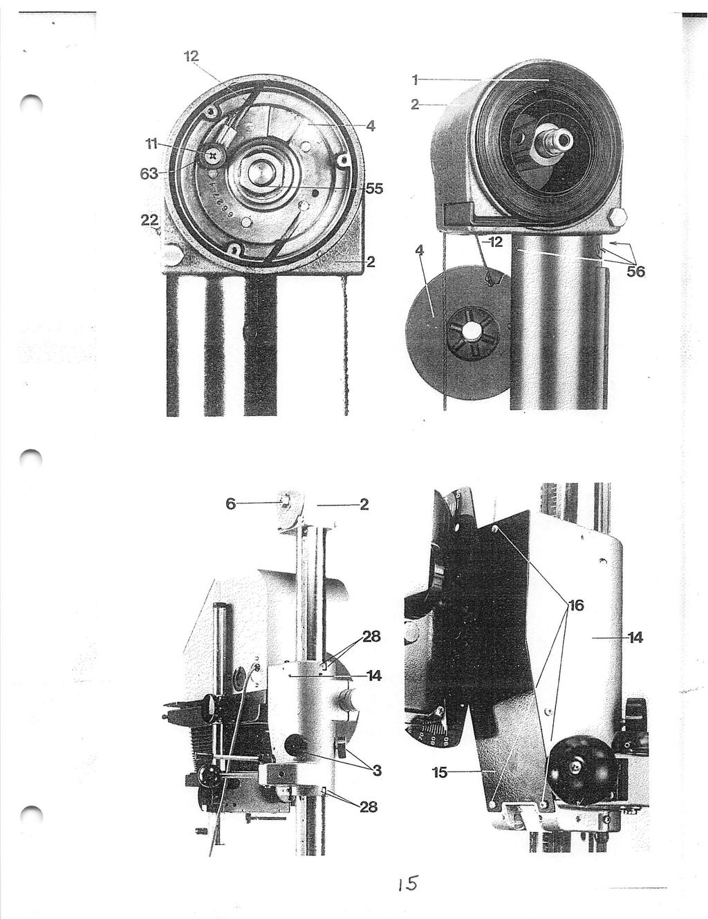
2 Durst Laborator 138 S Durst Laborator G 139 Servicing instructions L S G Replacing the counterweight spring The special tool required for this purpose is supplied to order and charged by Durst. Important: The counterweight spring (1) must always be replaced together with the column head (2). 1.) Move the enlarger head to the bottom of the column and lock it in position with the two knobs (3) on the carriage (14). 2,1 The column head (2) contains the counterweight spring (1) and the steel cable Td X

3
4 Durst Laborator 138 S Durst Laborator G 139 Servicing instructions L S - 1 G139-1 sheet 2 drum (4). Mount the special spanner (5) for tensioning the counten/veight spring on the nut (6) at the right-hand side of the column head, slightly tension, and secure the spanner (5) by engaging the hook (7). 3.) Unscrew the three cross-head screws (9) and remove the left-hand cover plate (8) of the column head (2). Tap out the locking pin (10) of the hexagonal nut (55) with a punch, and unscrew the nut. Then take out the cable drum (4). 4.) Remove the retaining hook (7) and carefully relax the spring (1) fully. Then remove the tensioning spanner (5). 5.) Unscrew the cross-head screw (11) and remove the retaining washer (63), then pull the steel cable (12) out of the column head (2). 6.) Unscrew the three screws (56) securing the column head on the column, and ^ remove the column head (2). Mount the new column head with the new counter weight spring in the same way. Again attach the tensioning spanner (5) to the right-hand side of the column head and tension the counterweight spring (1) by tuming the spanner (5) anti-clockwise through 4-6 tums. Then secure the spanner (5) with the hook (7). 7.) Draw the steel cable (12) into the new column head (2), attach to the cable daim (4) with the cross-head screw (11) and the retaining washer (63) and refit the cable drum (4). Screw in the left-hand hexagonal nut (55) and secure with the locking pin (10). Fit the left-hand cover panel (8) and ti^ten the three screws (9). 8.) Now remove the retaining hook (7) and the spanner (5)
5 12 5
6 Durst Laborator 138 S Durst Laborator G 139 Servicing instructions L S - 2 G Retensioning the counterweight spring The special tool required for this purpose is supplied to order and charged by Durst. 1.) Move the enlarger head to the bottom of the column and lock it in position on the carriage (14) with the two knobs (3). 2.) The column head (2) contains the counterweight spring (1) and the steel cable drum (4). Mount the special spanner (5) for tensioning the counterweight spring (1) on the nut (6) at the right-hand side of the column head, slightly tension, and secure by engaging the hook (7). 3.) Unscrew the three cross-head screws (9) and remove the left-hand cover plate (8) on the column head (2). Unscrew the cross-head screw {11) securing the cable and pull back the cable (12) sufficiently to allow the cable drum (4) to run past. 4.) To tension the countenrt/eight spring (1) turn the spanner (5) at the right hand side anti-clockwise as far as required and secure again with a hook (7). 5.) Secure the cable (12) again. Refit the left-hand cover plate (8) with the three crosshead screws (9). 6.) Now remove the retaining hook (7) and the tensioning spanner (5)

7
8 Durst Laborator 138 S Durst Laborator G 139 Servicing instructions L S - 3 G Replacing the steel cable The special tool required for this purpose is supplied to order and charged by Durst. 1.) Move the enlarger head to the bottom of the column and lock it in position with the two knobs (3) on the carriage. 2.) The column head (2) contains the countenveight spring (1) and the steel cable drum (4). Mount the special spanner (5) for tensioning the countena^eight spring on the nut (6) at the right-hand side of the column head, slightly tension and secure the spanner (5) by engaging the hook (7). Unscrew the three cross-head screws (9) and remove the left-hand cover plate (8) of %

9
10 V D u r s t L a b o r a t o r S L S - 3 Durst Laborator G 139 Servicing instructions g ^gg 3 sheet 2 the column head (2). Unscrew the cross-head screw (11) and remove together with the retaining washer (63). 4.) Unscrew the cross-head screws (16) and remove the cover plate (15). 5.) Hold the screw (64) and unscrew the nut (66). 6.) Release the bottom end of the cable from the screw (64) and pull out of the carriage (14) and the column head (2) from above. 7.) Pull a new cable (12) first through the column head (2) and then through the carriage (14). 8.) Place the upper end of the cable into the slot of the cable drum (4) and secure with the cross-head screw (11) and the retaining washer (63). 9.) Place the washer (66) over the screw (64), fit the lower end of the cable into the slot of the screw (64), form a loop over one half of the screw and fit the second washer (67). Push the whole assembly inside the carnage (14) and secure from above with the nut (65). 10.) Refit the cover plate (15), fit the left-hand cover plate (8) and gently release the special spanner (5) until the cable takes up the spring tension. Then unscrew the special spanner (5) and remove

11
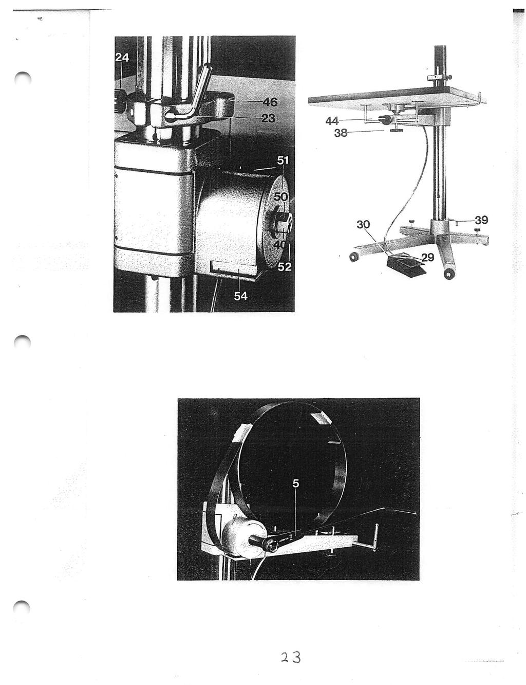
12 D u r s t L a b o r a t o r S Durst Laborator G 139 Servicing instructions L S - 4 G Retensioning the friction drive Eniargers of serial IMos. below 1363: To retension the friction drive, tighten the threaded shaft (13) on the carriage (14) by turning to the right as far as required. Eniargers of serial Nos. from 1363: Unscrew the three cross-head screws (16) and remove the black cover plate (15) of the carriage (14). Tension the spiral spring (18) by turning the square nut (17) underneath this cover plate. Eniargers of serial Nos. from 4619: Slack off the cross-head screw (19) accessible through the opening in the side. Slightly move the enlarger head up and down on the column and at the same time adjust the two cross-head screws (50) until the friction roller (21) grips correctly. Retighten the crosshead screw (19) IX
13 13
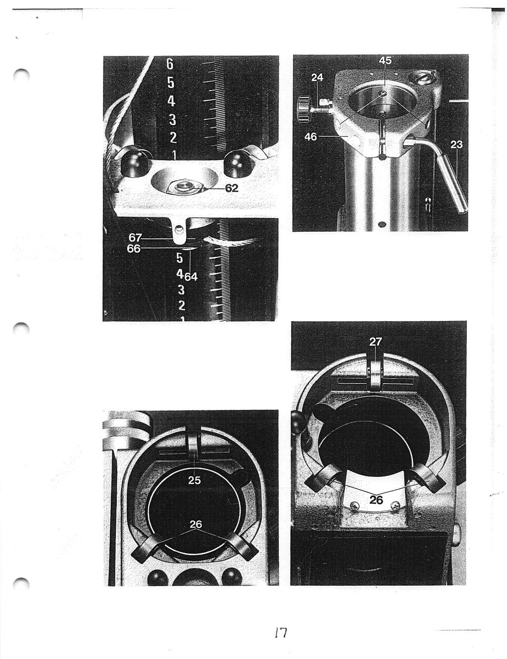
14 Durst Laborator 138 S Durst Laborator G 139 Servicing instructions Exchange of the guide rollers in the guide sleeve of the enlarger head instead of the two back rollers (upper and lower one), all Laborators 138 S and G 139 as of unit number will have two ball bearings which guarantee a sndoother movement of the enlarger head. These ball bearings can also be mounted as follows into units as of number : 1.) Block the counterweight spring (1) by tightening the threaded pin (22) on the back of the counterweight-spring housing (right-hand down). 2.) Mark the position of the enlarger head on the column and lift somewhat the head until the steel cable (12) becomes rather slack, then block the head by tightening the two set grips (3) on the sides of the guide sleeve (14) of the enlarger head. 3.) Swivel the enlarger head to the left through 90 and remove the black cover plate (15) of the sleeve (14) after loosening the three crosshead screws (16). 4.) Loosen the hexagonal nut (62) in the round cut-out on the front top side of the sleeve (14) with a spanner (18 mm) and draw out the steel cable (12). 5.) After loosening clamping lever (23) and screw (24), draw the complete upper part of the enlarger out of the lower column, place it on a table, and now, after loosening the three screws (56), draw the counterweight-spring housing out of the column- 6.) Loosen the two set grips (3) on the sleeve (14) of the enlarger head and pull out ' the enlarger head upwards until the upper back roller (25) can be removed easily and exchanged for ball bearings with pressed-in shaft. Take care that both rollers (26) and ball bearing (25) do not fall out of their mounting support. Then reinsert the enlarger head. 7.) Pull out the enlarger head just as far downwards and exchange here back roller (27) (like described under 6) for ball bearings. Then reinsert the enlarger head. 8.) Block again the enlarger head by tightening the two set grips (3) at the above designed position. Reinsert the enlarger head with column into the lower column and fix it by means of clamping lever (23) and screw (24). Mount counterweightspring housing (2), reinsert steel cable (12) into the sleeve (14) of the enlarger head and fix it. Remount black cover plate (15)
15 i5
16 D u r s t L a b o r a t o r S Durst Laborator G 139 Servicing instructions 9.) First loosen cautiously the two set grips (3) of sleeve (14} (holding the enlarger head fast by hand) and then loosen threaded pin (22) on the back of the counterweight-spring housing. Move the enlarger head up and down, taking care that all roller respect, ball bearings do rotate. If during moving it up and down the head should jam, or if one or more rollers don't rotate, the two ball bearings (25) and 27) should be adjusted by means of the two threaded pins (28) on the back of the sleeve (14), i. e. that they have to be tightened or loosened I (o
17 11
18 Durst Laborator 138 S Servicing instructions L S - 6 Retensioning the Bowden cable of the baseboard servo-adjustment 1.) Unscrew the two cross-head screws (29) and remove the rear cover panel (30) of the foot peda!. 2.) Tension the Bowden cable by turning the hexagonal nipple (31) anti-clockwise while holding the hexagonal nut (32) behind it. 3.) Replace the cover plate (30) and fix with the two cross-head screws (29). If the adjustment at the foot pedal is insufficient to retension the cable, a further nipple is provided for adjustment in the carrying arm for the baseboard: 1.) Unscrew and remove the baseboard. Pull off the circlip (34) and the washer (35) of the baseboard locking knob at the top of the carrying arm and pull out the knob (38) itself from underneath. 2.) Unscrew the six cross-head screws (37) and remove the panel (36) in the underside of the carrying arm. 3.) The end of the cable carries a further hexagonal nipple (33) for tensioning the Bowden cable in the same way as at the pedal end. 4.) The hexagonal nipple (33) must be withdrawn from the carrying arm in order to

19 19
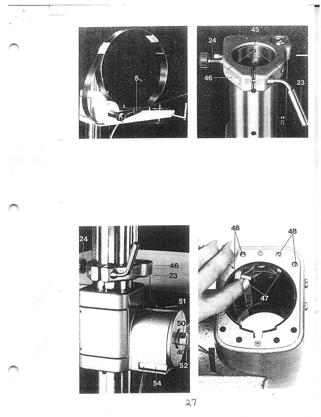
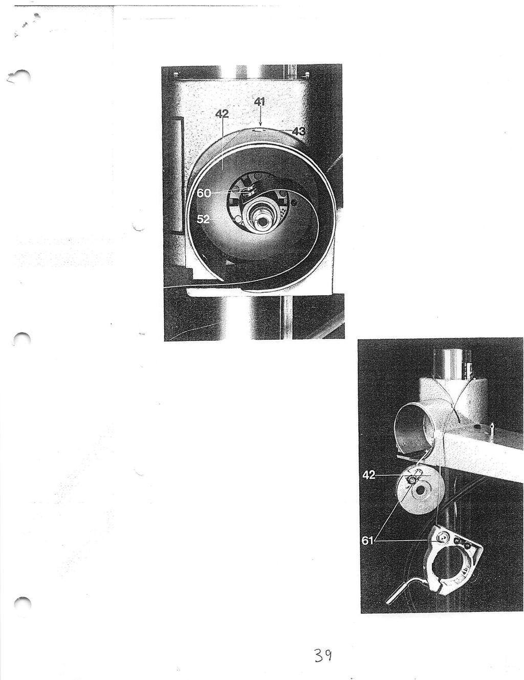
20 Durst Laborator 138 S Servicing instructions L S - 7 Retensioning the counterweight spring of the baseboard servo adjustment The special tool required for this purpose is supplied to order and charged by Durst. 1.) Release the clamping lever (23) and the milled knob (24) and lift the enlarger head with the top column out of the lower column. Unscrew the knob (38) and remove the baseboard. Place the lower half of the stand (base, lower column and baseboard carrying arm) on the work bench. Release the clamping lever (39) of the base and turn the lower column with the baseboard carrying arm clockwise through 90. Lock it in this position with the clamping lever (39). Move the carrying arm to its bottom position and lock it there by tightening the clamping knob (44). 2.) Mount the special spanner (5) for tensioning the counterweight spring on the hexagonal nut (40). Tighten the spanner (5) to allow the three grub screws (41) of

21
22 Durst Laborator 138 S Servicing instructions L S - 6 sheet 2 get at it with a spanner. To do this, unscrew the screw (57), clamp the cable with a screwdriver at the point (58) to release its tension and pull out the nipple (33) with its fitting (59). 5.) Now reassemble ail parts as described under 1. and 2. in the reverse sequence
23 a s
24 Durst Laborator 138 S Servicing instructions L138S-7 sheet 2 the steel cable dmm (42) to be slacked off in turn. These screws are accessible through the oblong opening (43) in the top of the countena/eight spring housing. These grub screws (41) secure the cable drum (42) on the shaft of the counter weight spring. 3.) To tension the counterweight spring, turn the spanner (5) anti-clockwise as far as required. 4.) To screw the grub screws (41) of the steel cable dmrn (42) into their grooves, turn the tensioning spanner (5) in either direction as required while screwing in the first grub screw, until this engages in the groove. On turning the tensioning spanner (5) the two other grub screws are then easily screwed in. 5.) Remove the tensioning gpanner (5) and release the clamping knob (44) to free the movement of the carrying arm
25 ^5
26 Durst Laborator 138 S Servicing instructions L 138 S - 8 Replacing the rollers in the baseboard carrying arm The special tool required for this purpose is supplied to order and charged by Durst. 1.) Slack off the clamping lever (23) and the shaft (24) on the clamping sleeve, and remove the upper column with the enlarger head. Unscrew the baseboard and lock its carrying arm in position with the clamping knob. 2.) Unscrew the three cross-head screws (45) of the clamping sleeve (46). 3.) Mount the special spanner (5) on the hexagonal nut (40) and tum anti-clockwise until the steel cable is slack and the clamping sleeve (46) can be pulled out from above. Carefully release the special spanner (5) so that the steel cable gets taut again and the clamping sleeve (46) contacts the counten^^eight spring housing. 4.) Release the locking knob of the carrying arm, press the foot pedal, and lift the ami off the column from above. 5.) Now replace the rollers (47) by new ones, or better still by a ball-bearing with pushed-in shaft. 6.) Press the foot pedal and refit the complete carrying arm on the column. Make sure that the rollers or ball-bearings do not drop out of their supports. Release the pedal and lock the arm by its clamping knob. 7.) Again tum the special spanner (5) anti-clockwise until the steel cable is slack and the clamping sleeve (46) can be inserted in the column. Fix the clamping sleeve to the column by tightening the three cross-head screws (45) and carefully slack off the special spanner (5) to allow the steel cable to retension itself. Remove the spanner (5) and unlock the clamping knob of the carrying arm. 8.) Mount the baseboard on the carrying arm, press the foot pedal and move the arm up and down on the column. Check that all rollers or ball-bearings are turning evenly. If the arm should jam during its up or down movement, or if one or more of the rollers or ball-bearings fail to turn, adjust the latter. To do this tighten or slack off the pairs of screw shafts (48) at the top rear and bottom front. 9.) Refit the upper column with the enlarger head and secure with the screw shaft (24) and locking lever (23) ^(o
27 X I
28 Durst Laborator 138 S Servicing instructions L S - 9 Changing the counterweight spring of the baseboard servo-adjustment The special tool required for this purpose is supplied to order and charged by Durst. 1.) Remove the upper column with the enlarger head and also the baseboard. 2.) Lock the carrying arm In position with its locking knob. Mount the special spanner (5) for tensioning the counterweight spring on the hexagonal nut (40). Tum the spanner anticlockwise to allow the three grub screws (41) of the steel cable drum (42) to be slacked off in tum. These grub screws are accessible through the oblong opening (43) In the top of the counterweight spring housing. Now carefuliy release the spanner (5) until the spring is fully relaxed. Then remove the spanner (5). 3.) Unscrew the three cross-head screws (45) and pull the clamping sleeve out of the

29
30 Durst Laborator 138 S Servicing instructions L S - 9 sheet -2-7.) Clean the entire spring housing and regrease. Remove the old spring from the core and the shaft (52) by unscrewing the two screws (60). Mount the new spring in the same way on the spring core and shaft (52). Do not screw the screws (60) tight; the spring must be able to move on the core. Lock the spring about 4 inches or 10 cm from the spring core in a vice. Mount the nut (40) and locking pin (50) on the shaft (52) and screw the special spanner (5) onto the nut (40). Turn the spanner (5) onto the nut (40). Turn the spanner (5) anti-dockwise to bend the spring and to allow it to be introduced into the housing. Push the spring with the core into the housing. Remove the carrying arm from the column to allow the shaft (52) to be fixed inside the arm with the securing cap (49). 8.) Press the foot pedal and fit the carrying arm in the column. Mount the clamping sleeve on the upper end of the column and secure with the three cross-head screws (45). 9.) Remove the nut (40) and locking pin (50), refit the cover plate (51) on the side of the spring housing, screw on the hexagonal nut (40) again and secure with the locking pin (50). Mount the special spanner (5) on the nut and slowly turn anti clockwise until the spring is fully folded up and tensioned. Thoroughly oil the spring during this operation. Hold the spanner (5) in this position and secure the angle bracket (54) at the end of the spring underneath the spring housing with the two cross-head screws (53). Turn the spanner clockwise until the spring is fully slack. 10.) Now tension the spring as required by tuming the special spanner (5) anti-clock wise through four to six turns. Move the carrying arm of the baseboard to its lowest position, and mount the steel cable drum (42) on the spring core with the three grub screws (41) which are accessible through the oblong opening in the top of the spring housing. To do this, turn the tensioning spanner (5) in either direction while screwing in the first grub screw until this can be fully screwed in. On tuming the tensioning spanner (5) in either direction the other two grub screws are then easily screwed in. Slowly release the spanner (5) until the steel cable is tensioned, then remove
31
 of the carrying arm, press the foot pedal, and lift the arm off the column from above. Remove the securing cap (49) of the counterweight spring shaft inside the arm. 4.")
32 D u r s t L a b o r a t o r S Servicing instructions L S - 9 sheet 2 upper end of the column. Slack off the locking knob (44) of the carrying arm, press the foot pedal, and lift the arm off the column from above. Remove the securing cap (49) of the counterweight spring shaft inside the arm. 4.) Refit the carrying arm on the column. Tap out the locking pin (50) of the hexagonal nut (40) with a punch and unscrew the nut (40) with a 24 mm spanner. Remove the cover plate (51) of the spring housing. Important: From this point on ail steps require two people. For safety both should wear thick leather gloves or wind thick rags round their hands for protection. 5.) Refit the hexagonal nut (40) and the locking pin (50) on the shaft (52) and screw on the special spanner (5). 6.) With extreme care first pull out the inner part of the broken spring with the aid of the special spanner (5). The important part of this operation is to have one person carefully turning the special spanner, while the second one holds back the turns of the spring so that only one turn is released at a time. After removing the first two turns, unscrew the special spanner (5) and pull out the remaining turns up to the point of fracture. During this operation hold the turns remaining rolled up in the housing alternately from above and below to prevent the spring from springing out. (See Figs, a and b.) Once the inner part of the broken spring is removed, grip the second part of the spring with a pair of heavy-duty pliers and pull them out turn by turn as described above. To remove the second part completely, unscrew the two cross-head screws (53) in the bottom of the spring housing. 30.
33 D u r s t L a b o r a t o r S Servicing instructions L S Replacing the steei cable of the baseboard servo-adjustment The special tool required for this purpose is supplied to order and charged by Durst. 1.) Remove the upper column of the enlarger head and also the baseboard. 2.) Relax the spring as described in the servicing instruction sheet 138 S - 9, step 2. 3.) Remove the spring from the housing. Remove an intact spring as follows: Unscrew the two cross-head screws (53), push a heavy-duty screwdriver between the housing and the angle bracket (54) and lever this out as far as possible. Push the screwdriver into one of the holes of the angle bracket (54) and screw the special spanner (5) onto the nut (4), Important: From this point on the operation needs two people. For safety both should wear thick leather gloves or wind thick rags round their hands for protection. 4.) One operator grips the angle bracket (54) and the screwdriver while the other turns the special spanner (5) anti-clockwise until the spring is easily pulled out by the first person. Continue pulling on the spring and gradually slack off the spring by tuming the spanner clockwise, always maintaining sufficient tension for easy
34 H

35 Durst Laborator 138 S Servicing instructions L S - 11 sheet 2 withdrawal of the spring. While the spring is being pulled, hold down the base of the enlargerwith one hand and one foot. Once the spring is fully pulled out to its stop, roll it up carefully and tie it together, placing it on the baseboard carrying a r m. Note: Never let go of the spring during rolling up and keep the spring itself always taut. (See Figs, c and d.) 5.1 Remove the special spanner (5), tap out the locking pin (50) and unscrew the nut (40). If the nut (40) is hard to unscrew, use a counter screw and nut which are screwed into the main shaft (52). 6,) Remove the cover plate (51), unscrew the three cross-head screws (45) and pull the clamping sleeve off the upper end of the column. Release the locking knob of the carrying arm, press the foot pedal, and lift the arm off the column from above. Remove the securing cap (49) of the counterweight spring shaft inside the arm. Press the pedal again and place the carrying arm on the column. Lock with its knot
36 Durst Laborator 138 S Servicing instructions L138S-11 7.) Pull the last part of the spring with the core and shaft (52) out of the housing and tie securely. Until it is secured, do not let go of this end Of the spring, either. Pull the cable drum (42) out of the housing and release both ends (61) of the cable. Replace the old cable by a new one and push the cable drum (42) back into the housing. Push the end part of the spring with the core and shaft (52) into the housing, checking that the shaft is correctly seated in the cable drum (42) and the bearing. 8.) Pull the carrying arm off the column as described before, and mount the securing cap (49) on the spring shaft (52) inside the arm. Replace the arm on the column and lock. Refit the clamping sleeve on the upper end of the column and secure with the three cross-head screws (45). Remount the cover plate (51) on the spring housing, screw in the nut (40) and tap in the locking pin (50). 9.) Mount the tensioning spanner (5), fully unroll the spring and push a heavy-duty screwdriver through one of the holes of the angle bracket (54) for an easier grip. Thoroughly oil the spring. 10.) Turn the tensioning spanner (5) anti-clockwise and wind the spring back into the housing. While one operator winds the spring, the other one holds the spring taut at the other end for easier winding up. Secure the angle bracket (54) with the two cross-head screws (53). 11.) The remaining steps of reassembly are identical with those of servicing instruction sheet L 138 S - 9, steps 10, 11 and sheet

37 Durst Laborator 138 S Servicing instructions L S - 9 sheet 3 11.) Mount the baseboard and move its carrying arm up and down the column to test the spring tension. If this is inadequate to raise the baseboard or, alternatively, if the latter shoots up too fast, readjust the tension as described in the servicing instruction sheet L 138 S ) Remount the upper column with the enlarger head. -^7
38 Durst Laborator 138 S Durst Laborator G 139 Servicing instructions L 138 S -10 G Resetting the friction coupling of the enlarger head adjustment If the friction of the enlarger head adjustment becomes insufficient after a short operating period, this is due to the need for running In the whole mechanism for optimum matching. Carry out any necessary adjustment as follows: 1.) Slightly slack off the cross-head screw (19). 2.) Evenly tighten or slack off the two screws (20) until the friction drive runs perfectly. 3.) Tighten the cross-head screw (19) again %
39 39
REPAIR INSTRUCTIONS. Cat. No Cat. No MILWAUKEE ELECTRIC TOOL CORPORATION. SDS Max Demolition Hammer. SDS Max Rotary Hammer
 Cat. No. 9-0 SDS Max Demolition Hammer Cat. No. -0 SDS Max Rotary Hammer MILWAUKEE ELECTRIC TOOL CORPORATION W. LISBON ROAD BROOKFIELD, WISCONSIN 00-0 8-9-0 d 000 8-9-0 d Special Tools Require Forcing
Replacing the Reciprocator on the SWF Compact Series Machine (601C and 1201C)
") Follow the instructions below to replace the reciprocator in the SWF Compact series machines. The tools required can be found in the tool kit that came with the machine. Preparation 1. First, place the
Follow the instructions below to replace the reciprocator in the SWF Compact series machines. The tools required can be found in the tool kit that came with the machine. Preparation 1. First, place the
REPAIR INSTRUCTIONS: CABLE
 The repair instructions describe replacing the Cable in the Easy Sun PARASOL Sunshade. These repair instructions are intended only for persons with experience of using the tools required. Please read the
Electric Skein Winder
 Electric Skein Winder Assembly and Use Package Contents 1 - Triangular Body (w/ motor) 1 - Cross Arm 1 - Left Foot (w/ yarn guide) 1 - Right Foot 1 - Adjustable Finger (w/ yarn clip) 3 - Adjustable Fingers
ELECTRIC TOOL CORPORATION
 Cat. No. -0 / Hex Demolition Hammer Cat. No. 0-0 Spline Rotary Hammer MILWAUKEE ELECTRIC TOOL CORPORATION W. LISBON ROAD BROOKFIELD, WISCONSIN 00-0 -9-00 d 000 -9-00 d SpecialTools Require Forcing discs
HDL(M)6 Nut/Screw Assembly
6 Nut/Screw Assembly") HDL(M)6 Nut/Screw Assembly Remove, repair, and reassemble the nut and screw assembly in your HDL series double lock vise. In these instructions when we refer to the front of the vise or nut/screw assembly,
HDL(M)6 Nut/Screw Assembly Remove, repair, and reassemble the nut and screw assembly in your HDL series double lock vise. In these instructions when we refer to the front of the vise or nut/screw assembly,
MS25 OPERATION MANUAL
 SAFETY INSTRUCTIONS SPECIFICATIONS OPERATING INSTRUCTIONS MAINTENANCE ADJUSTMENTS REPLACEMENT OF PARTS MS25 DIAGRAM MS25 PARTS LIST MS25 OPERATION MANUAL SAFETY INSTRUCTIONS Please read these instructions
SERIES I MILLING MACHINES
 INSTALLATION, OPERATION, MAINTENANCE, AND PARTS LIST SERIES I MILLING MACHINES TP5260 Revised: August 29, 2005 Manual No. M-450 Litho in U.S.A. Part No. M -0009500-0450 June, 2003 MAINTENANCE PROCEDURES
Before use please read & understand this manual, paying particular attention to the safety instructions.
 OPERATOR S MANUAL AND PARTS LIST 12 HAND PUSH ROLLER MOWER - THHMR Sales & Helpline 01793 333220 www.thehandy.co.uk Before use please read & understand this manual, paying particular attention to the safety
Converting the MGL SERVO to a MGL CAPSTAN SERVO.
 Parts supplied in kit Converting the MGL SERVO to a MGL CAPSTAN SERVO. 1 x bracket, 1 x bracket clamp, 4 x cap head screws M4 x 8 1 x nut M6, 1 x washer M6, 1 x drum, 1 x shear screw M3, 2 x grub screws
Replacing the Reciprocator on an SWF Multi-head.
 Replacing the Reciprocator on an SWF Multi-head. Follow the instructions below to replace the reciprocator in the SWF multi-head machines. The tools required are found in the tool kit that came with the
STEINBERGER TRANSTREM (TYPE 2) TECHNICAL DOCUMENT
 TECHNICAL DOCUMENT") STEINBERGER TRANSTREM (TYPE 2) TECHNICAL DOCUMENT These instructions apply to newer style TransTrems only (non-threaded ball type or modified threaded ball type). For purposes of discussion, these TransTrems
STEINBERGER TRANSTREM (TYPE 2) TECHNICAL DOCUMENT These instructions apply to newer style TransTrems only (non-threaded ball type or modified threaded ball type). For purposes of discussion, these TransTrems
Installation Instructions for FC2 & FC15 Forward Controls for the Super Magna
 Installation Instructions for FC2 & FC15 Forward Controls for the Super Magna It is highly recommended that you use a thread lock compound such as Loctite brand on all threads to keep them from vibrating
Top Innovations, Inc. Innovative Products to Make Your Life Easier. Model SP-402 Owner s Manual
 Top Innovations, Inc. Innovative Products to Make Your Life Easier Model SP-402 Owner s Manual THIS IS NOT A TOY! Adult supervision recommended Item contains sharp functional points and small parts Machine
Lumber Smith. Assembly Manual. If you are having problems assembling the saw and need assistance, please contact us at:
 Lumber Smith Assembly Manual If you are having problems assembling the saw and need assistance, please contact us at: 804-577-7398 info@lumbersmith.com 1 Step 1 Safety Carefully read the Owners Manual.
Cut-True 16M Manual Paper Cutter
 Cut-True 16M Manual Paper Cutter 2/2013 OPERATOR MANUAL FIRST EDITION TABLE OF CONTENTS TOPIC PAGE Specifications 1 Safety Guidelines 1 Assembly 2 Overview 3 Description of Equipment Parts 3-4 Operation
Astro-Physics Inc. 400QMD Lubrication/Maintenance Guide
 Astro-Physics Inc. 400QMD Lubrication/Maintenance Guide The following guidelines should be followed to lubricate the three main parts of the 400QMD mount. The QMD stands for Quartz Micro-Drive controller.
RTI TECHNOLOGIES, INC.
 RTI TECHNOLOGIES, INC. BRC500 & BRC550 Arbor/Spindle Mechanism Adjustment & Service Technical Instructions The arbor/spindle mechanism of the BRC500/550 is designed to be robust for long life. Occasionally
BABY WOLF LOOM. Assembly Instructions for Knocked-Down Looms
 BABY WOLF LOOM Assembly Instructions for Knocked-Down Looms BEFORE YOU BEGIN Please read through the directions before beginning to assemble your loom. Unpack the loom parts carefully. Do not throw away
No. 412, 414, 416 Operations Manual
 No. 412, 414, 416 Operations Manual CARE: Occasional oiling of moving parts with machine oil will ease operation and extend the life of the brake. Occasionally check and tighten the lower beam bracket
3.2.3 Rear Door Window and Quarter Window Carrier Assembly
 Tighten all bolts. Tighten bolts marked -1- and -2- in specified sequence. Tightening torque: 8 Nm Remaining bolts can be tightened in any sequence. Insert door window -3- through window recess without
TorqueMaster Replacement Spring
 TorqueMaster Replacement Spring Installation Instructions NOTE: Use these installation instructions in conjunction with the TorqueMaster Repair / Replacement Spring Program literature. Copyright 999 Wayne-Dalton
M14 MODULAR CHASSIS SYSTEM (MOD 1) INSTRUCTION MANUAL. West Springfield, MA Phone: (866) FAX: (413)
 INSTRUCTION MANUAL. West Springfield, MA Phone: (866) FAX: (413)") M14 MODULAR CHASSIS SYSTEM (MOD 1) INSTRUCTION MANUAL Troy Industries, Inc. WWW.TROYIND.COM West Springfield, MA 01089 Phone: (866) 788-6412 FAX: (413) 383-0339 Thank You M14/M1A MODULAR CHASSIS SYSTEM
M14 MODULAR CHASSIS SYSTEM (MOD 1) INSTRUCTION MANUAL Troy Industries, Inc. WWW.TROYIND.COM West Springfield, MA 01089 Phone: (866) 788-6412 FAX: (413) 383-0339 Thank You M14/M1A MODULAR CHASSIS SYSTEM
UNPACKING. Thank you for purchasing the Manual Capsule Filling Machine from KARISHMA PHARMA MACHINES.
 UNPACKING Thank you for purchasing the Manual Capsule Filling Machine from KARISHMA PHARMA MACHINES. Please take sufficient time and read this manual carefully before you start installation and operation
ABM International, Inc.
 ABM International, Inc. Lightning Stitch required 1 1.0: Parts List head and motor assembly (Qty. 1) Reel stand (Qty. 1) Needle bar frame clamp (Qty. 1) Motor drive (Qty. 1) 2 Cable harness with bracket
OTECO INC. MODEL ,000 PSI 4-1/16 PORT DM GATE VALVE MAINTENANCE MANUAL
 Page 1 of 7 OTECO INC. MODEL 45 4 5,000 PSI 4-1/16 PORT DM GATE VALVE MAINTENANCE MANUAL Page 2 of 7 TABLE OF CONTENTS 1. Assembly Blowout 2. Repair Kit Contents & Technical Specifications 3. Disassembly
6. Brakes. 6.1 Disc Brakes. General Notes on Disc Brakes
 6. Brakes 6.1 Disc Brakes General Notes on Disc Brakes There are a number of points to observe with disc brakes, this applies to both hydraulically and mechanically operated brakes and to those of all
Hardware and Components:
 Hardware and Components: (A) 4X 5/16 x 1 Carriage Bolt (B) 2X 5/16 x 2-1/4 Carriage Bolt (C) 2X 5/16 x 3-1/4 Hex Bolt (D) 2X 5/16 x 3/4 Hex Bolt (E) 2X 5/16 x 1-1/4 Hex Bolt (F) 5/16 x 2-1/4 Hex Bolt (G)
COMPACT 24 8 SHAFTS
 COMPACT 24 8 SHAFTS 1022-0001 1573 Savoie C. P. 4 Plessisville, Qc. Canada G6L 2Y6 TEL: 819-362-7207 FAX: 819-362-2045 www.leclerclooms.com nfo@leclerclooms.com On receiving the loom, unpack and lay out
COMPACT 24 4 SHAFTS Savoie C. P. 4 Plessisville, Qc. G6L 2Y6
 COMPACT 24 4 SHAFTS 1022-0000 1573 Savoie C. P. 4 Plessisville, Qc. G6L 2Y6 TEL: 819-362-7207 FAX: 819-362-2045 www.leclerclooms.com info@leclerclooms.com On receiving the loom, unpack and lay out the
CONTENTS PRECAUTIONS BEFORE STARTING OPERATION PREPARATION FOR OPERATION CAUTIONS ON USE OPERATION
 CONTENTS PRECAUTIONS BEFORE STARTING OPERATION ------------------------------------- 1 PREPARATION FOR OPERATION 1. Adjustment of needle bar stop position ---------------------------------------------------------
Maintenance Information
 16601023 Edition 2 January 2014 Air Impact Wrench 2705P1 Maintenance Information Save These Instructions Product Safety Information WARNING Failure to observe the following warnings, and to avoid these
Hardware and Components:
 Hardware and Components: (A) 5/16 x 2 Hex Bolt (B) 5/16 x 2-1/4 Hex Bolt (C) 5/16 x 2-1/2 Hex Bolt (D) 4X 5/16 x 3/4 Hex Bolt (E) 4X 5/16 x 1-1/4 Hex Bolt (F) 11X 5/16 Flat Washer (G) 12X 5/16 Nylock Nut
Taurean Sectional Garage Door INSTALLATION INSTRUCTIONS
 BEFORE YOU BEGIN MAKE SURE THESE INSTRUCTIONS ARE READ AND UNDERSTOOD COMPLETELY. THESE INSTRUCTIONS ARE INTENDED FOR PROFESSIONAL GARAGE DOOR INSTALLERS. ALL REFERENCES ARE TAKEN FROM THE INSIDE LOOKING
Revised
 Indentify Non-powered panels and separate from Powered panels. Non-powered panel shown at left.. Powered panel shown at left has powerway mounted at factory. Also separate panels by surface type, width
Fig Remove chain cover plate bolts. Fig Remove hammer member. Fig Loosen set screws at base of 12-tooth sprocket.
 Fig. 17.2. Remove chain cover plate bolts. Fig. 17.1. Remove hammer member. Fig. 17.3. Remove chain cover plate. Fig. 17.4. Loosen set screws at base of 12-tooth sprocket. Page 61 Fig. 17.5. Remove socket
WOLF PUP LOOM TM & WOLF PUP LT LOOM TM
 WOLF PUP LOOM TM & WOLF PUP LT LOOM TM Assembly Instructions FL3000 FL3006 FL3009 WOLF PUP WOLF PUP LT Find out more at schachtspindle.com Schacht Spindle Company 6101 Ben Place Boulder, CO 80301 p. 303.442.3212
MODEL T " SPIRAL CUTTERHEAD INSTALLATION INSTRUCTIONS
 MODEL T27449 8" SPIRAL CUTTERHEAD INSTALLATION INSTRUCTIONS The Model T27449 indexable insert spiral cutterhead is designed to replace the straightknife cutterhead on the Grizzly jointer Model G0490W/G0490XW
It is highly recommended that you use a thread lock compound such as Loctite brand on all threads to keep them from vibrating loose.
 Installation instructions for FC12 Forward Controls for Kawasaki Vulcan 750 It is highly recommended that you use a thread lock compound such as Loctite brand on all threads to keep them from vibrating
OPERATIONAL MANUAL V1.0. Removing/Replacing Blades
 OPERATIONAL MANUAL V1.0 BLUEROCK WS-212 Wire Stripper Removing/Replacing Blades CAUTION!! IMPORTANT!! DANGER!! WARNING!! DISCONNECT MACHINE FROM POWER BEFORE PROCEEDING!! Estimated Completion Time: 90
The wick in your heater needs replacing if, after repeated cleanings, any of the following conditions still exist:
 WICK REPLACEMENT The wick in your heater needs replacing if, after repeated cleanings, any of the following conditions still exist: Slow to light, hard movement of the wick adjuster knob, kerosene odor
TS4001. Model # 10 inch Table Saw addendum SETUP & OPERATION MANUAL
 SETUP & OPERATION MANUAL Features Powerful 13 amp motor Cast aluminum work table Riving knife Anti-kickback pawls Includes: 10 in. 24 tooth tungsten carbide tipped saw blade Rip fence Miter gauge Push
3D PRINTER. Pack 11. Anything you can imagine, you can make! 3D technology is now available for you at home! BUILD YOUR OWN
 BUILD YOUR OWN Pack 11 Anything you can imagine, you can make! 3D PRINTER Compatible with Windows 7 & 8 Mac OS X 3D technology is now available for you at home! BUILD YOUR OWN 3D PRINTER CONTENTS PACK
INSTALLATION TORSION SPRING FRONT OR REAR MOUNT LOW HEADROOM. 1 Cutting Vertical Track. 2 Fully Adjustable Jamb Brackets
 TORSION SPRING FRONT OR REAR MOUNT LOW HEADROOM Wayne Dalton, a division of Overhead Door Corporation P.O. Box 67, Mt. Hope, OH., 44660 Supplemental insert Copyright 2015 Wayne Dalton, a division of Part
EPPA2-KIT DUAL MONITOR ARM CONVERSION
 EPPA2-KIT DUAL MONITOR ARM CONVERSION EPPA2-KIT Rev A 10/17 Model EPPA2-KIT-XXX ASSEMBLY AND ADJUSTMENT EPPA2-KIT PARTS AND TOOLS PLEASE REVIEW these instructions before beginning the assembly and adjustment
BIFOLD FUTON FRAME TRINITY ARM. Seat Rails and Slats x 1. *Note: Use 4pc of 100mm Bolts and 4pc of 60mm Bolts to attach the arms to the Stretchers.
 1A Parts in this box. 2pc with extra holes 2pc with extra holes & plastic stoppers Arms x 2 Back Rails and Slats x 1 Full Size: Slat Supports x 6 3pc are longer for the Back deck Back Side Rails x 2 Seat
The Bowflex Revolution XP Home Gym Assembly Instructions. P/N: Rev ( /0 )
") P/N: 001-7057 Rev ( /0 ) The Bowflex Revolution XP Home Gym Assembly Instructions 2 Table of Contents Before You Start... 2 Tools You Will Need / Hardware Contents... 3 Box Contents... 6 Assembling Your
P/N: 001-7057 Rev ( /0 ) The Bowflex Revolution XP Home Gym Assembly Instructions 2 Table of Contents Before You Start... 2 Tools You Will Need / Hardware Contents... 3 Box Contents... 6 Assembling Your
LEG CURL IP-S1315 INSTALLATION INSTRUCTIONS
 LEG CURL IP-S35 INSTALLATION INSTRUCTIONS Copyright 2009. Star Trac by Unisen, Inc. All rights reserved, including those to reproduce this book or parts thereof in any form without first obtaining written
Due to possible damage in shipping, the vertical stop assembly has been removed from this machine.
 Due to possible damage in shipping, the vertical stop assembly has been removed from this machine. To assemble, insert the threaded rod through the shroud opening in the top of the machine. Start the four
SCHACHT STANDARD FLOOR LOOMTM
 SCHACHT STANDARD FLOOR LOOMTM FL3109 FL3111 FL3113 FL3115 FL3121 FL3123 FL3125 FL3127 FL3310 FL3312 FL3314 FL3316 FL3322 FL3324 FL3326 FL3328 Assembly instructions LOW CASTLE LOOM IN MAPLE Find out more
600mm COMPOUND MITRE SAW ASSEMBLY INSTRUCTIONS. MODEL NO: MBS600D Part No: GC05/12
 600mm COMPOUND MITRE SAW MODEL NO: MBS600D Part No: 6461516 ASSEMBLY INSTRUCTIONS GC05/12 INTRODUCTION Thank you for purchasing this CLARKE Mitre Saw. Before attempting to use the product, it is essential
NAMES OF PARTS. 1 Thread guide for bobbin winding 2 Take-up lever. 3 Upper thread tension dial. 4 Face cover. 5 Thread guide for upper threading
 6 Presser foot thumb screw 9 Spool pins (retractable) 8 Shuttle cover 5 Thread guide for upper threading 7 Presser foot 4 Face cover NAMES OF PARTS.r4r : VjN S* ;WWE7-17 16 15 MODEL 860.-.-.- --. :.---.-
INSTRUCTIONS FOR USE Pro-Ject 9 Pro-Ject 9c Pro-Ject 9cc Pro-Ject 10cc Pro-Ject 12cc
 INSTRUCTIONS FOR USE Pro-Ject 9 Pro-Ject 9c Pro-Ject 9cc Pro-Ject 10cc Pro-Ject 12cc 1 Finger lift * 2 Headshell 3 Tonearm tube 4 Tonearm rest 4a Removable transport lock 5 Tonearm lift lever 6 Anti-skating
Brother Industries, Ltd. Nagoya, Japan
 4. 2001. This service manual has been compiled for explaining repair procedures of the MODEL XL-6562, XL6452, XR- 46. This was produced based on up-to-date product specifications at the time of issue,
S10C. Instructions. Version S10C-V1c
 S10C Instructions Version S10C-V1c To celebrate our fortieth anniversary, we have transformed the spinning wheel it all started with: the S10. The new S10 Concept spinning wheel makes it possible to customize
Depending on the size you ordered you will have either 5 Foot sections which will build the 10 Foot frame or 6 Foot sections which will build the 12
 XL Quilting Frame 1 Depending on the size you ordered you will have either 5 Foot sections which will build the 10 Foot frame or 6 Foot sections which will build the 12 Foot frame Printed 2 June 2014 Updated
Ensat driving tools...
 nsat driving tools... On this page, you can configure the optimum tool for your application. A configuration is provided in the following as an illustrative example. The article number is composed of two
Oxford /Hoyer. Professional Series. Advance Lift SERVICE MANUAL Rev A
 Oxford /Hoyer Advance Lift Professional Series SERVICE MANUAL CONTENTS Pages 3-4 Inspection Criteria of the Oxford/Hoyer Advance Page 5 Testing of the Oxford/Hoyer Advance Pages 6-15 Service and Maintenance
1 of 2 3/3/2017 4:49 PM
 1 of 2 3/3/2017 4:49 PM Front Door Window, Assembly Overview 1 - Window guide - Inserted on flange 2 - Door 3 - Inner window recess seal - Inserted on flange 4 - Bolt - 20 Nm 5 - Carrier assembly - Window
MODEL H-9 HEAVY DUTY BENCH-TYPE UNDERCUTTER INSTRUCTIONS
 MODEL H-9 HEAVY DUTY BENCH-TYPE UNDERCUTTER INSTRUCTIONS CAPACITY: Between centers - 32" long x 12" diameter. Between roller V- supports - 35" long x 17" diameter. Maximum armature weight - 200 lbs. SAW
Side Winder R o u t e r L i f t.
 Woodpeckers PRECISION WOODWORKING TOOLS Side Winder R o u t e r L i f t. INSTALLATION INSTRUCTIONS The wrench handle must be pointing left in order to fully insert or remove it. Lift Wrench Once fully
Bunk Pod Front Entry Assembly Instructions
 Bunk Pod Front Entry Assembly Instructions www.podtime.co.uk enquiries@podtime.co.uk Working House Ltd How to assemble your pod This step by step guide will show how to assemble your pod(s) on site. It
Baby Grande or Grande Crank Shade with Cables and Housing Installation Instructions
 Baby Grande or Grande Crank Shade with Cables and Housing Installation Instructions Tools Needed Drill 3/8 Metal Drill Bit Screwdriver (Flat & Phillips) Measuring Tape Pencil 4 Level Plumb Line ¼ Masonry
OPERATING INSTRUCTIONS MODULGRAV. Tel. +49 (0) Fax +49 (0) homepage:
 Fax +49 (0) homepage:") OPERATING INSTRUCTIONS MODULGRAV Kolpingstraße -7 D-784 Singen / Htwl. Postfach 80 D-784 Singen / Htwl. Tel. +49 (0) 77 88-0 Fax +49 (0) 77 88 66 e-mail: info@elma-ultrasonic.com homepage: www.elma-ultrasonic.com
OPERATING INSTRUCTIONS MODULGRAV Kolpingstraße -7 D-784 Singen / Htwl. Postfach 80 D-784 Singen / Htwl. Tel. +49 (0) 77 88-0 Fax +49 (0) 77 88 66 e-mail: info@elma-ultrasonic.com homepage: www.elma-ultrasonic.com
LifeGear G1 /HOME GYM ITEM NO.: 63100
 LifeGear G1 /HOME GYM ITEM NO.: 63100 OWNER S MANUAL IMPORTANT: Read all instructions carefully before using this product. Retain this owner s manual for future reference. The specifications of this product
Inventory (Figure 2)
") MODEL T10127 12" SPIRAL CUTTERHEAD INSTRUCTIONS The Model T10127 indexable insert spiral cutterhead is designed to replace the straightknife cutterhead from the Grizzly jointer Model G0609. The total procedure
MODEL T10127 12" SPIRAL CUTTERHEAD INSTRUCTIONS The Model T10127 indexable insert spiral cutterhead is designed to replace the straightknife cutterhead from the Grizzly jointer Model G0609. The total procedure
S E L E C T I O N. Upper Back. User manual
 and S E L E C T I O N T H E S T R E N G T H E V O L U T I O N User manual and and The identification plate of the and manufacturer, affixed to the frame on the side opposite the padded rest, gives the
Javelin Integra Inspired Design Precision Engineering
 Javelin Integra Inspired Design Precision Engineering USER INSTRUCTIONS Thank you for choosing the Keencut Javelin Integra. Every effort has been made to bring you a precision engineered product with the
pô1e -/C INSTRUCTION MANUAL FOR SEWING MACHINE WHITE
 pô1e -/C -- INSTRUCTION MANUAL I FOR SEWING MACHINE WHITE Retain these numbers for future reference. Model No. Serial No. The Model No. is located on Rating Plate. The Serial No. is located on Bed Plate.
Replacing the build plate clamps
 Repair manual Replacing the build plate clamps Instructions The build plate clamps hold the glass plate in place on the heated bed. There are two fixed in place at the back of the heated bed and two at
5 Maintenance 5.1 Guideway and Wipers
 5 Maintenance 5.1 Guideway and Wipers 5.1 Page 26 of 41 The grinding carriage runs with hardened rollers on hardened steel straps (2). The steel straps (2) are positioned on the grinding bed (1) and tensioned
The Portable Open Source 3D Printer
 http://web.archive.org/web/201502142011/http://www.tantillus.org/build_3.html Page 1 of 12 captures 12 Oct 12 - Feb 15 The Portable Open Source 3D Printer Home Start Case X/Y Axis Extruder Z Axis Electronics
FABA. Installation Instructions. Conductor Bar System. Publication #FABA-03 3/1/04 Part Number: Copyright 2004 Electromotive Systems
 FABA Conductor Bar System Installation Instructions Publication #FABA-03 3/1/04 Part Number: 005-1062 Copyright 2004 Electromotive Systems 1S 100 Z Installation Instructions Contents: Basic Diagram - -
Basic steps to time the Gammill quilting machine s rotary sewing hook
 Basic steps to time the Gammill quilting machine s rotary sewing hook 1.) Turn the machine off and unplug it. 2.) With the needle bar in the raised position, remove the bobbin and bobbin case. 3.) Remove
Inventory (Figure 2)
") MODEL T10130/T10126 6" & 8" SPIRAL CUTTERHEAD INSTRUCTIONS The Model T10126/T10130 indexable insert spiral cutterheads are designed to replace straightknife cutterheads from the Grizzly jointer Models
MODEL T10130/T10126 6" & 8" SPIRAL CUTTERHEAD INSTRUCTIONS The Model T10126/T10130 indexable insert spiral cutterheads are designed to replace straightknife cutterheads from the Grizzly jointer Models
Installation and Assembly - Universal Articulating Swivel Double-Arm for 42" - 60" Plasma Screens
 Installation and Assembly - Universal Articulating Swivel Double-Arm for 42" - 60" Plasma Screens Models: PLAV 70-UNL, PLAV 70-UNL-S PLAV 70-UNLP, PLAV 70-UNLP-S R This product is UL Listed. It must be
NILUS II COUNTER-BALANCED
 NILUS II COUNTER-BALANCED 36" 45" 60" 1026-0000 1027-0000 1028-0000 On receiving the loom, unpack and lay out the loom components. Do NOT discard any packing material until all parts are inventoried. Check
Motorized M3 AX7200 Rotary-Style Gasket Cutter Operating Instructions
 Motorized M3 AX7200 Rotary-Style Gasket Cutter Operating Instructions INTRODUCTION Congratulations! You are the owner of the finest rotary-style gasket cutter in the world. Originally developed and patented
M4 Foot Operated Underpinner Instruction Manual
 M4 Foot Operated Underpinner Instruction Manual M4 Walker Rd, Bardon Hill, Coalville, Leicestershire LE67 1TU, England Tel. +44 (0)130 1692, Fax +44 (0)130 16929 e mail sales@framerscorner.co.uk M4 Underpinner
Hollywood Swing Away 2 and 4 Bike Racks Assembly and Installation Guide
 Hollywood Swing Away 2 and 4 Bike Racks Assembly and Installation Guide Tools Required: two adjustable wrenches, pliers, ¾ socket wrench recommended Note: please do assembly near your vehicle as you Can
SPIDA SAW OPERATIONS MANUAL
 SPIDA SAW OPERATIONS MANUAL CM SERIAL NUMBER. OCTOBER 2000 CONTENTS Page description 1.) Contents 2.) Safety First 3.) CM Overview 4.) CM Specifications 5.) CM Installation 6.) CM Operation Setting the
Castle Frame Assembly Table AT-8. Diagnostics Manual. Castle, Inc. Petaluma, CA
 Castle Frame Assembly Table AT-8 Diagnostics Manual Castle, Inc. Petaluma, CA 800-282-8338 Solutions Index Adjusting the Tabletop.. 8.01 Adjusting the Fence... 8.02 Aligning the Arm... 8.10 Adjusting Bracket..
UNDERPINNERS CS 88 & CS 89 FOOT-OPERATED PNEUMATIC. Technical and User Manual. Version 1 au 12 / 01. Cassese / Communication
 UNDERPINNERS CS 88 & CS 89 FOOT-OPERATED PNEUMATIC Technical and User Manual Version 1 au 12 / 01 Cassese / Communication CS88 / CS 89 - Technical and User Manual CONTENTS PAGE N INTRODUCTION ACCESSORIES
JVice Care and Maintenance Thanks for purchasing a Jvice. If properly looked after your Jvice will give a lifetime of tying pleasure.
 JVice Care and Maintenance Thanks for purchasing a Jvice. If properly looked after your Jvice will give a lifetime of tying pleasure. Although it is manufactured from highest quality materials any metal
PEARL DRUM PEDAL. Instruction Manual
 PEARL DRUM PEDAL Instruction Manual Congratulations on your purchase! To get optimum performance from your P-932 / P-932L / P-931 Drum Pedal, please read this Instruction Manual before playing. Assembly
Baby Grande or Grande Crank Shade with Cables and Housing Installation Instructions
 Baby Grande or Grande Crank Shade with Cables and Housing Installation Instructions Tools Needed Drill 3/8 Metal Drill Bit Screwdriver (Flat & Phillips) Measuring Tape Pencil 4 Level Plumb Line ¼ Masonry
MODEL H " BYRD SHELIX CUTTERHEAD INSTRUCTIONS
 MODEL H9291 12" BYRD SHELIX CUTTERHEAD INSTRUCTIONS The Model H9291 12" Byrd Shelix cutterhead is designed to replace the straight-knife cutterhead on the Grizzly jointer Model G0609. The total procedure
Star Trac Turbo Trainer Assembly & Setup
 Star Trac Turbo Trainer Use the following procedures to unpack and assemble your Turbo Trainer manufactured by Star Trac. UNPACKING AND PARTS LIST Position the shipping carton so the Heavy End logo is
INSTRUCTION BOOK EASILY REMOVEABLE DIES FOR YOUR BINDING NEEDS OD 4012 SHOWN WITH THE OPTIONAL PALM SWITCH FOR THE OD 4012
 RHIN- -TUFF INSTRUCTION BOOK FOR THE OD 4012 AND INTRODUCTION TO THE OD 4012 BINDING MODULES www.rhin-o-tuff.com HD 4270 OD 4300 HD 4470 HD 4171 HD 8370 PAL 14 HD 4170 PAL 14 EASILY REMOVEABLE DIES FOR
Page 1. SureMotion Quick-Start Guide: LARSACC_QS 1st Edition - Revision A 03/15/16. Standard Steel Bolt/Screw Torque Specifications
 R K C T I Repair Kit Product Compatibility Repair Kit # Linear Actuator Assembly # LARSACC-013 LARSACC-014 LARSD2-08T12BP2C (12-in travel) LARSD2-08T24BP2C (24-in travel) C P I R K 1 ea Ball Screw with
SERVICE MANUAL MODEL BLE1 AT. U.S.A. Canada EU Au. N.Z. Vol Serial Numbers. From
 SERVICE MANUAL MODEL BLE1 AT Serial Numbers From U.S.A. Canada EU Au. N.Z K6 148120 307467 7041 70771 To Vol. 3.0 1.Construction of Covers New Adjusting Gauge Distance of lower looper tip from center of
Maintenance & Parts list for:
 Maintenance & Parts list for: Industrial gun GB 2 Juni 2017 This Maintenance & Parts list for industrial gun is prepared by : Winchester Europe Service V. Parbst & Søn as a comprehensive maintenance guide
Setup & Operating INSTRUCTIONS. for (FOR PIN FITTING AND ROD RECONDITIONING)
") I-AG-400A Setup & Operating INSTRUCTIONS for SUNNEN AG-400 PRECISION GAGE (FOR PIN FITTING AND ROD RECONDITIONING) AG-400 Precision Bore Gage Range:.375 to 2.687 in. (9,5-68mm) Graduation of Dial:.0001
I-AG-400A Setup & Operating INSTRUCTIONS for SUNNEN AG-400 PRECISION GAGE (FOR PIN FITTING AND ROD RECONDITIONING) AG-400 Precision Bore Gage Range:.375 to 2.687 in. (9,5-68mm) Graduation of Dial:.0001
Installation and Assembly - Universal Articulating Swivel Double-Arm for 42" - 60" Plasma Screens
 Installation and Assembly - Universal Articulating Swivel Double-Arm for 42" - 60" Plasma Screens Models: PLAV 70-UNL, PLAV 70-UNL-S PLAV 70-UNLP, PLAV 70-UNLP-S R This product is UL Listed. It must be
SERVICE MANUAL AND PARTSLIST
 SERVICE MANUAL AND PARTSLIST Next 20 CONTENTS WHAT TO DO WHEN... 1~3 SERVICE ACCESS FACE COVER... 4 TOP COVER... 4 BASE COVER... 5 REAR COVER... 6 FRONT COVER... 7 MECHANICAL ADJUSTMENT NEEDLE THREAD TENSION...
Queen Wingback Bed King Wingback Bed
 Parts and Hardware List A. Side Rails with Attachment Hooks 2 pcs B. Foot Rail 1 pc C. Head Rail 1 pc D. Center Support Slat 1 pc E. Leg Supports 3 pcs F. Support Slats 4 pcs G. Flat Washers 8 pcs H. Lock
ASSEMBLY AND ADJUSTMENT
 EPPA MONITOR ARM EPPA Rev A 10/17 Model EPPA-XXX ASSEMBLY AND ADJUSTMENT EPPA MONITOR ARM PARTS AND TOOLS PLEASE REVIEW these instructions before beginning the assembly and adjustment procedures. Check
JOY 2 SPINNING WHEEL
 INSTRUCTIONS JOY 2 SPINNING WHEEL SINGLE & DOUBLE TREADLE WITH A SLIDING HOOK FLYER JASW110618V8 Ashford Handicrafts Limited Factory and Showroom: 415 West Street PO Box 474, Ashburton 7700 New Zealand
Hydraulic Clamp Carrier. Installation & Operation Manual
 Hydraulic Clamp Carrier Installation & Operation Manual Hydraulic Clamp Carrier Installation & Operation Manual Quick Machinery Company 8272 Peninsula Drive Kelseyville, CA 95451 phone: (707) 272-6719