INSTRUCTIONS AND PARTS LIST POWER HAMMER
|
|
|
- Nora McKenzie
- 6 years ago
- Views:
Transcription

1 INSTRUCTIONS AND PARTS LIST POWER HAMMER DAKE (Division of JSJ) 724 Robbins Road Grand Haven, Michigan Phone Fax Web: customerservice@dakecorp.com technicalsupport@dakecorp.com 1

2 Set up and Operation of the Once you remove the power hammer from the packaging you will need to install the shaping dies to be used and the wheels. WARNING!!! Unplug the power hammer from the electrical source before changing the dies. A. Remove the 6 bolts from the adjustable bottom sleeve. B. Remove the adjustable bottom sleeve from the side plates. C. Insert die holder with the desired die attached into the slider. Make sure the die holder is bottomed into the slider. D. Tighten the two hex socket set screws to secure the upper die holder. D D A A C B 2

3 Set up and Operation of the E. Rotate the adjusting screw handle to move the bottom adjustment rod down. F. Insert the die holder with the desired die attached into the adjustable bottom sleeve. Make sure the die holder is bottomed into the adjustable bottom sleeve. G. Snug up the two hex socket set screws on the adjustable bottom sleeve to hold the die holder firmly but still allow it to move up by turning the adjusting screw handle. F G E 3
4 Set up and Operation of the I. Insert adjustable bottom sleeve (B) and attach six bolts through the side plates and into the adjustable bottom sleeve. I I B 4
5 Set up and Operation of the J. Make sure the lock screw on the adjustment bottom sleeve is loose. K. Rotate adjusting screw handle to move the lower die to the upper die. WARNING!!!! For safe operation and possible die damage always adjust the gap between the upper die half and the work piece to a minimum of ¼ before starting motor. ¼ minimum gap before starting motor J K 5
6 Set up and Operation of the L. Check the two set screws on the die holder to see if they are tight. These hold the lower die firmly in place. M. The upper and lower dies need to be lined up. If they do not line up, loosen the bolts holding the dies to the die holders and align the dies. Don t forget to retighten these bolts. M L 6
7 Set up and Operation of the WARNING!!! Before turning on power to your Dake power hammer be sure to review all safety stickers and warnings. N. With the motor turned on, the upper die holder will begin to oscillate. Rotate the adjusting screw handle to move the lower die up until just before it touches the upper die. This is a good initial setting to try shaping with. O. With the die gap set to your desired setting, tighten the lock screw on the adjustable bottom sleeve to lock in the gap setting. Repeat steps N and O for any future gap adjustments, up or down. O N 7
8 8
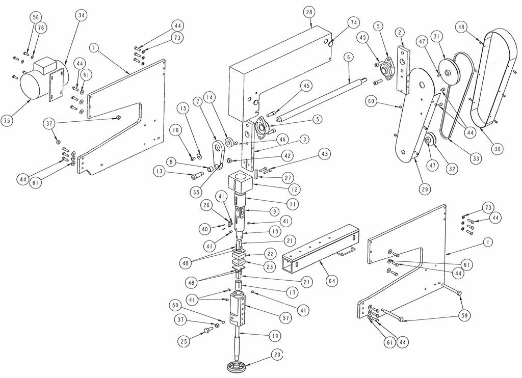
9 Item # Part description Qty Part # 1 Side Plate Rear spacer Plate Front Mount Plate Bolt Flange Bearing Offset Shaft (27 ) Connecting Rod Cast Bronze Bushing Slider Top Collet Slide Gulide & Bushing Shoulder Bolt Bearing Washer (center hole 5/16 bolt) Socket head cap screw 5/16-18UNC X Bottom Collet Bottom Adjustment Rod Hand Wheel Die Holder Upper Die 1 23 Lower Die Knurled Head Screw 1-1/ Alignment Key Support Key Top Cover (Red) Belt Cover Inner (Red) Cover Belt (Red) Top Pulley Bottom Pulley Belt 1 34 Electric Motor Grease Zerk (1/4 x 28 straight) Nut 1/2-13 UNC Socket head Cap Screw 6-32 x ½ Half Dog Hex Socket Set Screw 3/ UNC x ½ 42 Nut 5/8-11 UNC Socket Head Cap Screw 3/8-16 UNC x
10 ½ 44 Grade 8 Hex Cap Screw 3/8-16 UNC x /4 45 Grade 8 Hex Head Cap Screw 5/ UNC X 1-1/4 46 Socket Head Cap Screw ¼-20 x 3/ Key Stock 3/16 x 3/ ? 48 Socket Head Cap Screw ¼-20 x ¾ UHMW Poly Rod Grade 8 Hex Bolt 5/16-18 x Bottom Sleeve Cross Brace RivNuts ¼ Grade 8 Washer 3/ Bottom Spacer, Base Grade 8 Nut 5/ Grade 8 Hex Bolt ½-13 x Belt Grade 9 Lock Washer 3/ Finishing Plug Washer 5/16 Grade Parts Not Shown Qty Part # Stand Caster Standard 300lbs. Capacity Caster Swivel, Total Locking 300 lbs
11 You are now ready to start shaping metal Everyone has their own technique when it comes to shaping and you will need to find your own. So, practice, think, practice and think some more before practicing again. We have found that like forming by hand, it is easier to get the desired shape using the Dake power hammer by using several steps to sneak up on the final shape, versus trying to get the shape in one step. A good source of information on how to use a power hammer type machine like this, is reading any of the several books on sheet metal shaping currently available. Have fun and be safe!!!!! Dake Maintenance You need to maintain your Dake power hammer as you would any other piece of shop equipment. More use requires more maintenance. This should include, but not limited to checking and greasing bearings and bushings regularly. Check for any loose components, lines and connections and replace as needed. 11


12 Safety stickers that are located on the Dake power Hammer WARNING!!!! Review all safety stickers before operating this machine. Part number Part number Part number Part number Part number

13 110 volt Machine 13

14 220 volt single phase machine 14
ITEM NO. PART NO DESCRIPTION QTY.
 PUMP MAINTENANCE ITEM NO. PART NO DESCRIPTION QTY. 1 52002 Center Case 1 2 52052 Back End Plate 1 3 52051 Front End Plate 1 4 55090 Octagonal Nut 1 5 53001 Idler Gear 1 6 53002 Drive Gear 1 7 28062 Bushing
1. Fasten press to bench or work surface using the mounting holes provided (Item 3).
.") INSTRUCTIONS AND PARTS LIST FOR Models 1-202, 1-204, 1-210, and 1-220 Air Arbor Presses WARNING LABELS To the left is the safety Alert symbol. When you see these safety alert symbols on your press, be
INSTRUCTIONS AND PARTS LIST FOR Models 1-202, 1-204, 1-210, and 1-220 Air Arbor Presses WARNING LABELS To the left is the safety Alert symbol. When you see these safety alert symbols on your press, be
M2 Assembly. M2 Sub-Assemblies mm Belt Sub-Assembly mm Belt Sub-Assembly Spider Sub-Assembly... 4
 M2 Assembly Table of Contents M2 Sub-Assemblies... 3 630mm Belt Sub-Assembly... 3 702mm Belt Sub-Assembly... 3 Spider Sub-Assembly... 4 Idler Bolt Sub-Assembly... 8 Y Motor Sub-Assembly... 9 X Motor Sub-Assembly...
PPM-5710 JK HEAVY DUTY SKID PLATE ASSEMBLY Version 2.0
 SYNERGY MFG. 870 INDUSTRIAL WAY, SAN LUIS OBISPO, CA (805) 242-0397 PPM-5710 JK HEAVY DUTY SKID PLATE ASSEMBLY Version 2.0 GENERAL NOTES: These instructions are also available on our website; www.synergymfg.com.
It is highly recommended that you use a thread lock compound such as Loctite brand on all threads to keep them from vibrating loose.
 Installation instructions for FC12 Forward Controls for Kawasaki Vulcan 750 It is highly recommended that you use a thread lock compound such as Loctite brand on all threads to keep them from vibrating
Retro Fit Gearbox Mount. Assembly Instructions. Assembly Instructions. Before You Start. General Information. Manual No M
 Retro Fit Gearbox Mount Assembly Instructions Treker 4400NT & 4400ST Series Before You Start Assembly Instructions Manual No. 700-372M! When you see this symbol, the subsequent instructions and warnings
Removing the Z-Axis lead screw
 Page 1 of 8 TITLE: Sabre Z-Axis Lead Screw Replacement Procedure Gerber FastFact #: 5048 Supplied by: Gerber Hardware Support Last Modified: June 14, 2007 Summary: Tools used: The following procedure explains
25-200H. 12 Planer / Jointer. with Helical Cutterhead. Parts List.
 25-200H 12 Planer / Jointer with Helical Cutterhead 4001824 Parts List www.rikontools.com CABINET ASSEMBLY PARTS EXPLOSION & PARTS LIST KEY NO. DESCRIPTION KEY NO. DESCRIPTION 1 Pan Head Screw M6x12 P25-200H-1
DO35 MAINTENANCE INSTRUCTIONS
 CUSTOMER INFORMATION SHEET NO. 038 DO35 MAINTENANCE INSTRUCTIONS (DO35 V3 LAUNCHED PRODUCTION JUNE 2017) Table of Contents 1.0 Replacing Spindle Bushes V3... 22 2.0 Replacing Locking Mechanism V3... 6
INSTALLATION OF WELLS SUPER QUICK CHUCK LEFT HAND ON RED WING LATHE
 DENTAL, INC. TECHNICAL BULLETIN Q824-022510 5860 FLYNN CREEK ROAD READ ALL INSTRUCTIONS P.O. BOX 106 BEFORE PROCEEDING COMPTCHE, CALIFORNIA, U.S.A. 95427 SAVE THIS FOR FUTURE REFERENCE www.wellsdental.com
This manual will aid in the assembly of the FireBall V90 and FireBall X90. The assembly of both machines will be identical, unless specified.
 This manual will aid in the assembly of the FireBall V90 and FireBall X90. The assembly of both machines will be identical, unless specified. Step #1 Lay all parts out to verify quantities. (2) 2 x 25-1/4
RYOBI. 10 in. (254 mm) TABLE SAW MODEL NO. BTS15 REPAIR SHEET
 TABLE SAW MODEL NO. BTS15 REPAIR SHEET") RYOBI 0 in. ( mm) TABLE SAW MODEL NO. BTS REPAIR SHEET FIGURE A 0 0 0 0 The model number will be found on a plate attached to the motor housing. Always mention the model number in all correspondence regarding
RYOBI 0 in. ( mm) TABLE SAW MODEL NO. BTS REPAIR SHEET FIGURE A 0 0 0 0 The model number will be found on a plate attached to the motor housing. Always mention the model number in all correspondence regarding
Power Train Lift Max. Capacity: 1,250 lbs.
 655 EISENHOWER DRIVE OWATONNA, MN 55060 USA PHONE: (507) 455-7000 TECH. SERV.: (800) 533-6127 FAX: (800) 955-8329 ORDER ENTRY: (800) 533-6127 FAX: (800) 283-8665 INTERNATIONAL SALES: (507) 455-7223 FAX:
ABM International, Inc. Navigator Assembly Manual
 ABM International, Inc. 1 1.0: Parts List Tablet (Qty. 1) Tablet mount (Qty. 1) NOTE: Mount may appear and operate different then image below Control Box (Qty. 1) Motor Power Supply (Qty. 1) 2 X-axis motor
MODEL T21973 METAL BLADE GUIDE SET INSTRUCTIONS
 MODEL T21973 METAL BLADE GUIDE SET INSTRUCTIONS Introduction (Figure 1) These Euro-style blade guides replace the blade guides on the G0531, G0531B, G0566, G0568, and G0569 bandsaw. Tools Needed Wrench
MAG-CONV Basic, 48, 48R & Midline Front Mount
 Parts Required: Tools Used: Mag Wheels Brakes Brake Rods Mounting Bracket Anti Tippers 7/16" Wrench Screw Driver Rubber Mallet 5/8 Wrench 5mm Allen Wrench Step Execution Figures 1 Remove front 5" total
ABM International, Inc.
 ABM International, Inc. Lightning Stitch required 1 1.0: Parts List head and motor assembly (Qty. 1) Reel stand (Qty. 1) Needle bar frame clamp (Qty. 1) Motor drive (Qty. 1) 2 Cable harness with bracket
SatNOGS. SatNOGS Rotator v3 Mechanical Assembly. This is the assembly guide for the third version of the SatNOGS Rotator.
 SatNOGS SatNOGS Rotator v3 Mechanical Assembly This is the assembly guide for the third version of the SatNOGS Rotator. Written By: Pierros Papadeas 2017 satnogs.dozuki.com Page 1 of 19 INTRODUCTION Notes:
Warnings. Description. Prior to Installation Tools Needed
 Warnings Failure to act in accordance with the following may result in death or personal injury. The JT Strong Arm Stabilizer System is intended to eliminate chassis movement in travel trailers and fifth
30DC Speed Lathe Manual
 30DC Speed Lathe Manual The Crozier Model 30DC Speed Lathe is our most popular model. It has many standard features not found on any other machine in its class or price range. Standard Features 3/4 HP
RBP-1215B-RX DODGE RAM QUAD CAB RX3
 RBP-1215B-RX3 2002-2017 DODGE RAM 15-3500 QUAD CAB RX3 Passenger side RX-3 Side Step Drill Template Passenger side rear Modular Bracket (6) L Support Brackets Driver side rear Modular Bracket Driver side
METRIC BOlTS. Size Grade Torque 8mm ft/lbs. 10mm ft/lbs. 12mm ft/lbs. 14mm ft/lbs. 16mm ft/lbs.
 8/16 HJ31005,Rev 7 BOlT TORQUE SPECIfICATIONS METRIC BOlTS STANDARD BOlTS Size Grade Torque 5/16 5 18 ft/lbs. 3/8 5 30 ft/lbs. 7/16 5 50 ft/lbs. 1/2 5 75 ft/lbs. 5/8 5 150 ft/lbs. 3/4 5 290 ft/lbs. Size
Code Product Qty 1 Top Vertex 3 2 Hot End Housing 1 3 Bottom Vertex 3 4 Print Platform Lock 3 5 End Stop Holder 3 6 Filament Feeder Motor Bracket 1 7
 List of Parts Code Product Qty 1 680mm Extrusion 3 2 Power Supply 1 3 240mm Extrusion 9 4 42mm Nema 17 Stepper Motor 3 5 Slider-Hotend Connecting Rod 6 6 48mm Nema 17 Stepper Motor 1 7 Linear Rail with
AndyMark DART 12.
 AndyMark DART 12 Part Number Description QTY These Parts Are Pre-Assembled by AndyMark am-0031 Bearing, 3/16"ID (R3) 1 am-0209 Bearing, 3/8"ID 1614ZZ 2 am-1028 Screw, #10-32x3/8 Pan Head Philips 8 am-1121
STEP 1 STEP 2 LEVELER KIT OPTION MOBILE CASTER KIT OPTION
 B SERIES INDUSTRIAL BENCHES TOOLS REQUIRED FOR ASSEMBLY Socket set, Open end wrench set, Cordless drill with 3/8" socket bit (Magnetic recommended). BEFORE ASSEMBLY Read through the assembly instructions
FRAME BRACKET. Doing Our Best to Provide You the Best. Ford. Page 1. BOlT TORQUE SPECIFICATIONS HJ31000,Rev 0
 2-13 HJ31000,Rev 0 Ford BOlT TORQUE SPECIFICATIONS METRIC BOlTS Size Grade Torque 8mm 8.8 23 ft/lbs. 10mm 8.8 45 ft/lbs. 12mm 8.8 78 ft/lbs. 14mm 8.8 125 ft/lbs. STANDARD BOlTS Size Grade Torque 5/16 5
Submersible Turbine Assembly Manual
 Submersible Turbine Assembly Manual Table of Contents Submersible Turbine Kit Assembly Page Recommended Equipment... 2 Assembly Instructions...3-9 Special Tool Schematics... 10 Symbol Key Action Safety/Caution
Bead Roller Operating, Servicing, and Safety Instruction Manual
 Bead Roller Operating, Servicing, and Safety Instruction Manual CAUTION: Read and Understand These Operating, Servicing, and Safety Instructions, Before Using This Machine. 1-800-67-26 10 Cooperative Way
Gared Pro-S Portable Backstop
 Models: 9616 & 9618 Installation, Operation and Maintenance Instructions Please read all instructions before attempting installation or operation of these units SAVE THESE INSTRUCTIONS FOR FUTURE USE PUBLICATION
MODEL H " BYRD SHELIX CUTTERHEAD INSTRUCTIONS
 MODEL H9291 12" BYRD SHELIX CUTTERHEAD INSTRUCTIONS The Model H9291 12" Byrd Shelix cutterhead is designed to replace the straight-knife cutterhead on the Grizzly jointer Model G0609. The total procedure
Page 1. SureMotion Quick-Start Guide: LARSACC_QS 1st Edition - Revision A 03/15/16. Standard Steel Bolt/Screw Torque Specifications
 R K C T I Repair Kit Product Compatibility Repair Kit # Linear Actuator Assembly # LARSACC-013 LARSACC-014 LARSD2-08T12BP2C (12-in travel) LARSD2-08T24BP2C (24-in travel) C P I R K 1 ea Ball Screw with
INSTRUCTION MANUAL AND PARTS LIST MODEL 14-10
 VERTICAL BAND SAWS INSTRUCTION MANUAL AND PARTS LIST MODEL 1-10 DAKE/PARMA WHEN ORDERING PARTS GIVE COMPLETE SERIAL NUMBER OF MACHINE GIVE PART NUMBER AND NAME GIVE AMOUNT REQUIRED Unless the above data
RECOMMENDED SPARE PARTS FOR NORMAL ONE (1) YEAR OPERATION OF VD CRUSHER
 YEAR OPERATION OF VD CRUSHER") RECOMMENDED SPARE PARTS FOR NORMAL ONE (1) YEAR OPERATION OF VD CRUSHER 2 ea. VD-65 Toggle 2 ea. VD-70A Right Hand Bearing Split Bushing 2 ea. VD-70B Left Hand Bearing Split Bushing 2 ea. VD-82 Plate for
RECOMMENDED SPARE PARTS FOR NORMAL ONE (1) YEAR OPERATION OF VD CRUSHER 2 ea. VD-65 Toggle 2 ea. VD-70A Right Hand Bearing Split Bushing 2 ea. VD-70B Left Hand Bearing Split Bushing 2 ea. VD-82 Plate for
INSTALLATION INSTRUCTIONS CHEVY C-10 INDEPENDENT FRONT SUSPENSION
 INSTALLATION INSTRUCTIONS 73-87 CHEVY C-10 INDEPENDENT FRONT SUSPENSION Please read these instructions completely before starting your installation. Assemble suspension on vehicle before powder-coating
OPERATIONAL MANUAL V1.0. Removing/Replacing Blades
 OPERATIONAL MANUAL V1.0 BLUEROCK WS-212 Wire Stripper Removing/Replacing Blades CAUTION!! IMPORTANT!! DANGER!! WARNING!! DISCONNECT MACHINE FROM POWER BEFORE PROCEEDING!! Estimated Completion Time: 90
Page 1. SureMotion Quick-Start Guide: LACPACC_QS 1st Edition - Revision A 03/15/16
 R K C T I Repair Kit Product Compatibility Repair Kit # Linear Actuator Assembly # LACPACC-002 LACPACC-003 LACP-16TxxLP5 (0.5-in lead screw pitch) LACP-16TxxL1 (1-in lead screw pitch) C P I R K 4 ea Flanged
MODEL H9565 BALL BEARING GUIDE FOR G0513/G0514 INSTRUCTION SHEET
 MODEL H9565 BALL BEARING GUIDE FOR G0513/G0514 INSTRUCTION SHEET Introduction The Model H9565 replaces the upper and lower Euro-style guides on your G0513 or G0514 Bandsaw. Inventory (Figure 1) A. Upper
Parts Catalog. S-Series Slicer Manual Frozen Option S13. Model:
 , 07 995 ECN 08 Parts Catalog S S-Series Slicer Manual Frozen Option Model: S 05/0/07 Rev. G IMPORTANT! TO EXPEDITE SHIPMENT OF PARTS, ALWAYS SPECIFY MODEL, REV, PART NUMBER, AND SERIAL NUMBER OF UNIT.
Installation Instructions for FC2 & FC15 Forward Controls for the Super Magna
 Installation Instructions for FC2 & FC15 Forward Controls for the Super Magna It is highly recommended that you use a thread lock compound such as Loctite brand on all threads to keep them from vibrating
MODEL 36 Di-Acro Hand Shear
 OPERATOR S MANUAL & INSTRUCTIONS MODEL 36 Di-Acro Hand Shear Di-Acro, Incorporated PO Box 9700 Canton, Ohio 44711 3713 Progress Street N.E. Canton, Ohio 44705 330-455-1942 330-455-0220 (fax) Revised 01/02
400A 40113V, 401A 40120V, & 401AL 40120VL ALUMINUM VERTICAL 4000 LB LIFT INCLUDES SCREW LEG ASSEMBLY INSTRUCTIONS
 12/11/07 PAGE 1 OF 12 400A 40113V, 401A 40120V, & 401AL 40120VL ALUMINUM VERTICAL 4000 LB LIFT INCLUDES SCREW LEG ASSEMBLY INSTRUCTIONS Thank you for purchasing our product! *Please read these instructions
RS 34 / 36 Squeeze Roller assembly instructions
 RS 34 / 36 Squeeze Roller assembly instructions 83 259 Step 1. Assemble new bearing Make sure the tapper is going the correct direction Use fixture to press bearings into upper and lower rollers Press
MODEL T28173/T28174 ROLLER TABLES INSTRUCTIONS
 MODEL T28173/T28174 ROLLER TABLES INSTRUCTIONS FOR MODELS MFD. SINCE 10/17 For questions or help with this product contact Tech Support at (570) 546-9663 or techsupport@grizzly.com Rails Rollers Reversible
Geology, Prospectors, Mining, Metallurgy, Assaying, Environmental, Geotechnical
 LEGEND INC. Geology, Prospectors, Mining, Metallurgy, Assaying, Environmental, Geotechnical 988 Packer Way Sparks, NV 89431 Tel: (786) 786-3003 Fax: (775) 786-3613 Email: info@lmine.com Web: www.lmine.com
Astro-Physics Inc. 400QMD Lubrication/Maintenance Guide
 Astro-Physics Inc. 400QMD Lubrication/Maintenance Guide The following guidelines should be followed to lubricate the three main parts of the 400QMD mount. The QMD stands for Quartz Micro-Drive controller.
Installation instructions for FC14S Forward Controls for Shadow ACE and Aero 1100
 Installation instructions for FC14S Forward Controls for Shadow ACE and Aero 1100 It is highly recommended that you use a thread lock compound such as Loctite brand on all threads to keep them from vibrating
Referencing 0,0 position
 Page 1 of 11 TITLE: SABRE X-Axis Lead Screw Replacement Procedure Gerber FastFact #: 2013 Supplied by: Gerber Hardware Support Last Modified: March 1, 2011 Summary: The following procedure explains how
Operating Instructions
 Operating Instructions Holding the material against the angle gauge slide it into the forming head. Be sure that the material remains against the gauge until work is finished. NOTE: This machine will handle
CNC Router Parts. Standard Rack & Pinion Drive Assembly Instructions
 CNC Router Parts Standard Rack & Pinion Drive Tools List The following tools will be used for assembly and installation of the Standard Rack & Pinion Drive: Imperial Allen Wrench Set - 3/32", 5/32", 3/16",
TABLE OF CONTENTS DESCRIPTION. Safety Instructions Assembly Operation... 7
 TABLE OF CONTENTS DESCRIPTION PAGE Warranty... 1 Safety Instructions... 2 Assembly... 3 Operation... 7 #360 Grain Cleaner Drawings... 8 #360 Grain Cleaner Parts List... 10 Utility Auger Option Drawing...
OPERATION & MAINTENANCE MANUAL
 OPERATION & MAINTENANCE MANUAL AUTOMATIC PECAN CRACKER Food Processing Equipment and Machinery Specializing in the Pecan Industry Mailing: PO Box 817, Mansfield, Louisiana 71052 Located: 280 Independence
55000/55010 Installation Instructions
 A. Install 55015 B. Bolt roof rails, 55020/55025, to front hoop. C. Assemble 55026 D. To install without drilling into bumper. E. If mounting directly to bumper. A. 55015 Installation Instructions 55000/55010
OWNERS MANUAL MODEL F660 HIP SLED
 OWNERS MANUAL MODEL F HIP SLED QUESTION? As a quality home gym supplier we are committed to your complete satisfaction. If you have questions, or find missing or damaged parts, we will guarantee your complete
Number Wheeler P/N Description Set Rex P/N Notes Base 1 J Support, Right 1 J Support, Left 1 J Nut (M8)
") 1 603500 Base 1 J001 2 603501 Support, Right 1 J002 3 603502 Support, Left 1 J003 4 600328 Nut (M8) 4 5 600130 Spring Washer (8mm) 4 6 600344 Roll Pin (M6x30) 4 7 600129 Socket Hd Cap Screw (M8x25) 4 8
1 603500 Base 1 J001 2 603501 Support, Right 1 J002 3 603502 Support, Left 1 J003 4 600328 Nut (M8) 4 5 600130 Spring Washer (8mm) 4 6 600344 Roll Pin (M6x30) 4 7 600129 Socket Hd Cap Screw (M8x25) 4 8
SERIES I MILLING MACHINES
 INSTALLATION, OPERATION, MAINTENANCE, AND PARTS LIST SERIES I MILLING MACHINES TP5260 Revised: August 29, 2005 Manual No. M-450 Litho in U.S.A. Part No. M -0009500-0450 June, 2003 MAINTENANCE PROCEDURES
Assembly. Item G7 Qty 1. Item D4. M10 x 55 mm Allen Bolt. Item D5. Qty 2. Item E13 Qty 4 M10 Flat Washer. Item B18. M8 x 30 mm Allen Bolt (Black)
") ACCESSORY FITMENT LIST These are all the accessories you will need to complete the assembly of your product. The following accessories are supplied in a pack and should be checked before attempting assembly
ACCESSORY FITMENT LIST These are all the accessories you will need to complete the assembly of your product. The following accessories are supplied in a pack and should be checked before attempting assembly
TITAN2-EDGE Public Access Computer Station Dual Track
 TITAN2-EDGE Public Access Computer Station Dual Track TITAN2-EDGE Rev A 6/17 Model TITAN2-EDGE ASSEMBLY AND ADJUSTMENT TITAN2-EDGE PARTS AND TOOLS PLEASE REVIEW these instructions before beginning the
30AUTO Speed Lathe Manual
 30AUTO Speed Lathe Manual Standard Features 3/4 HP Motor Air-Collet Closure 1800 RPM, Single Speed Electric Brake Cast Housing 5C Collets 3 Phase / 240 Volts DESCRIPTION: The Crozier Model 30AUTO Automotive
FRAME BRACKET. Doing Our Best to Provide You the Best. Ford F /2, 6 1/2 & 8 Boxes. BOlT TORQUE SPECIFICATIONS. 7/17 HJ31001,Rev 3
 Ford F150 5 1/2, 6 1/2 & 8 Boxes 7/17 HJ31001,Rev 3 BOlT TORQUE SPECIFICATIONS METRIC BOlTS Size Grade Torque 8mm 8.8 23 ft/lbs. 10mm 8.8 45 ft/lbs. 12mm 8.8 78 ft/lbs. 14mm 8.8 125 ft/lbs. STANDARD BOlTS
AX1001. Smith/Functional training Combo-free weight ASSEMBLY INSTRUCTIONS
 AX1001 Smith/Functional training Combo-free weight ASSEMBLY INSTRUCTIONS EXPLODED DIAGRAM 83 84 84 85/86 87 87 88 89 90 91 62 64 64 64 64 64 64 65 65 65 65 66 66 65 66 66 65 63 63 66 67 68 55 66 66 70
Allow 60 from door face
 Setbacks Allow 60 from door face TOOLS NEEDED Tape Measure Marker or Pencil Masonry Drill Bit 3/8 Hammer Drill Hammer Socket Wrenches and Wrench: 9/16, 1/2, 7/16, 1/4 drive socket wrench and 1/2 socket
Nancy s Knit Knacks LLC 4 Yard Option Upgrade Kit Assembly Instructions and User Manual
 Nancy s Knit Knacks LLC 4 Yard Option Upgrade Kit Assembly Instructions and User Manual Thank you for purchasing our 4 Yard Option (4YO) Upgrade Kit. To install this upgrade you are simply going to assemble
Hardware and Components:
 Hardware and Components: (A) 5/16 x 2 Hex Bolt (B) 5/16 x 2-1/4 Hex Bolt (C) 5/16 x 2-1/2 Hex Bolt (D) 4X 5/16 x 3/4 Hex Bolt (E) 4X 5/16 x 1-1/4 Hex Bolt (F) 11X 5/16 Flat Washer (G) 12X 5/16 Nylock Nut
OPERATOR S MANUAL MAINTENANCE MANUAL PARTS LIST TURFCO. 60 Inch Seeder. Product Number Starting Serial Number H00801 PATENT PENDING
 0 Inch Seeder OPERATOR S MANUAL MAINTENANCE MANUAL PARTS LIST TURFCO 0 Inch Seeder Product Number 0 Starting Serial Number H000 PATENT PENDING Manual Number DANGER - IF INCORRECTLY USED THIS MACHINE CAN
Parts Manual for MODELS: ZKH52222 ZKH52252 ZKH61252
 Parts Manual for MODELS: ZKH52222 ZKH52252 ZKH61252 Professional Quality Lawn Care Equipment since 1945 THIS MANUAL INCLUDES UPDATES ON PAGES 6,10, & 20. Yazoo/Kees Power Equipment policy is to improve
J D SQUARED INC. NOTCH MASTER Tube and Pipe Notcher Operating Instructions
 Copyright (c) 2006 J D SQUARED INC. www.jd2.com NOTCH MASTER Tube and Pipe Notcher Operating Instructions Angled Notches PATENT PENDING Straight Notches Offset Notches Tube Clamp Slider Tube Clamp Exploded
Parts Sheet. RSX096 High Force, Rod Style Actuator EXPLODED VIEW - RSX _00_RSX09. * Specify stroke length when ordering A/R = As Required
 RSX0 High Force, Rod Style Actuator Parts Sheet 00_00_RSX0 EXPLODED VIEW RSX0 0 0 0 PART NO or ITEM Config. Code DESCRIPTION QTY. 0 Leadscrew/Rollerscrew (Standard) Leadscrew/Rollerscrew (TRR Option) 0
TABLE OF CONTENTS DESCRIPTION. Safety Instructions Assembly Operation... 7
 TABLE OF CONTENTS DESCRIPTION PAGE Warranty... 1 Safety Instructions... 2 Assembly... 3 Operation... 7 #360 Grain Cleaner Drawings... 8 #360 Grain Cleaner Parts List... 10 Utility Auger Option Drawing...
TO OPERATE AUTO-GUIDE POWER. 24 Gauge Pittsburgh Operating Instructions FLANGING ATTACHMENT
 24 Gauge Pittsburgh Operating Instructions Holding the material against the angle gauge slide it into the forming head. Be sure that the material remains against the gauge until work is finished. Make
PARTS LIST MS 2892-D
 PARTS LIST MS 89-D 8--00 8-0-000 KNIFE BRACE (TOP) 8--00 RIGHT KNIVE (UHMW) 8--00 LEFT KNIFE (UHMW) 8-0-00 KNIFE BRACE (UNDER) NC0-8-0 0 FLAT HEAD SOCKET CAP SCREW STAINLESS /8- X " LG NC0-9-00 0 LOCK
Tin Lizzie 18 Assembly Instructions
 Tin Lizzie 18 Assembly Instructions Revision: 07/29/16 Table of Contents Aides 3 Before You Begin 5 Aides 5 Tools 6 Perfect Stitch Parts 2 12 Modify the Machine 12 Prepare Drill Templates 12 Front Display
Parts Catalog. S-Series Slicer Smart Manual SG13. Model:
 , 07 99507 ECN 065 Parts Catalog S-Series Slicer Smart Manual Model: SG SG 0/0/07 Rev. G IMPORTANT! TO EXPEDITE SHIPMENT OF PARTS, ALWAYS SPECIFY MODEL, REV, PART NUMBER, AND SERIAL NUMBER OF UNIT. GLOBE
HYDRAULIC MOWER AHRM4H, HRM48H Parts Catalog INDEX HOME TRACTOR ATTACHMENTS APPLICATION CHART
 R Ingersoll HYDRAULIC MOWER AHRM4H, HRM48H Parts Catalog 8-3091 HOME TRACTORS ATTACHMENTS PAINT GENERAL INFO INDEX Deck. Belt and Idler Pulley...5 Mounting Bracket...7 Rear Wheels...7 Hydraulic Drive...9-13
MODEL 83 Pail Handler
 MORSE MFG. CO., INC. 727 West Manlius Street P.O. Box 518 East Syracuse, NY 13057-0518 Phone: 315-437-8475 Fax: 315-437-1029 Email: service@morsemfgco.com Website: www.morsemfgco.com COPYRIGHT 2005 MORSE
SB-32V Drill Press OWNERS MANUAL
 724 Robbins Road, Grand Haven, MI 49417 Phone: 616-842-7110 800-937-3253 Fax: 616-842-0859 800-846-3253 Web: www.dakecorp.com E-mail: customerservice@dakecorp.com SB-32V Drill Press OWNERS MANUAL FOR YOUR
Installation instructions for FC17 Forward Controls for Triumph Rocket III Roadster
 Installation instructions for FC17 Forward Controls for Triumph Rocket III Roadster It is highly recommended that you use a thread lock compound such as Loctite brand on all threads to keep them from vibrating
SUPER PRO GUN & SUPER PRO GUN II
 MAGNUM VENUS PRODUCTS Maintenance & Repair Manual Part No. M6707-1-1 Revision 04.14.01 Maintenance & Repair Corporate HQ & Mfg. Phone: (727) 573-2955 Fax: (727) 571-3636 Email: info@magind.com Web: www.magind.com
INSTALLATION OF WELLS SUPER QUICK CHUCK LEFT HAND ON BALDOR LATHE
 DENTAL, INC. TECHNICAL BULLETIN Q832-022510 5860 FLYNN CREEK ROAD READ ALL INSTRUCTIONS P.O. BOX 106 BEFORE PROCEEDING COMPTCHE, CALIFORNIA, U.S.A. 95427 SAVE THIS FOR FUTURE REFERENCE THIS PRODUCT IS
OPERATOR'S MANUAL 46" SNOW BLADE. Model Numbers OEM IMPORTANT: READ SAFETY RULES AND INSTRUCTIONS CAREFULLY
 OPERATOR'S MANUAL 46" SNOW BLADE Model Numbers 190-833-OEM IMPORTANT: READ SAFETY RULES AND INSTRUCTIONS CAREFULLY MTD PRODUCTS INC. P.O. BOX 368022 CLEVELAND, OHIO 44136-9722 PRINTED IN U.S.A. FORM NO.
OWNERS MANUAL. Model No LB. POLY PRO SPIKER/SPREADER. CAUTION: Read Rules for Safe Operation and Instructions Carefully
 OWNERS MANUAL Model No. -0301 CAUTION: Read Rules for Safe Operation and Instructions Carefully 17 LB. POLY PRO SPIKER/SPREADER Safety Assembly Operation Maintenance Parts PRINTED IN U.S.A. FORM NO. 78
FM2113PC/FM2114PC SBC Top Mount Alt, w/ A/C & Power Steering
 10) At this time assemble the power steering bracket and pump assembly from the instructions provided with the power steering bracket beginning at step 7. Return to step 10 on this sheet when complete.
EllisSaw.com. EllisSaw.com P.O. Box Verona, WI
 P.O. Box 9019 Verona, WI 9-019 GENERAL OPERATING & SAFETY INSTRUCTIONS * READ INSTRUCTIONS BEFORE USE * CAUTION: Disconnect power supply cord from power source when doing repair work or changing belt.
installation guide 1 GUIDE#: pwb-assault-001
 assault WAKEBOARD tower installation guide INSTALLATION SUPPORT 1 important information This Aerial wakeboard tower fits motor boats with 76-108 inch wide beam widths. This measurement is taken from the
3D PRINTER. Pack 11. Anything you can imagine, you can make! 3D technology is now available for you at home! BUILD YOUR OWN
 BUILD YOUR OWN Pack 11 Anything you can imagine, you can make! 3D PRINTER Compatible with Windows 7 & 8 Mac OS X 3D technology is now available for you at home! BUILD YOUR OWN 3D PRINTER CONTENTS PACK
BEAST THE. Tube and Pipe Notcher Operating Instructions. Notches In Bends Straight Notches. Angled Notches. Offset Notches
 Copyright (c) 2007 J D SQUARED INC. www.jd2.com THE BEAST Tube and Pipe Notcher Operating Instructions Notches In Bends Straight Notches Angled Notches PATENT PENDING Offset Notches Assembly After unpacking
6 BLADE CUTTER MODEL # PCC-6 OPERATION MANUAL
 4511 WAYNE AVENUE PHILADELPHIA PA 19144 TEL: 888-800-2663 FAX: 800-582-9643 6 BLADE CUTTER MODEL # PCC-6 OPERATION MANUAL CONTENTS I. INTRODUCTION TO BOND PCC-6 / MACHINE SPECIFICATIONS II. SAFETY PRECAUTIONS
MANUAL DE MONTAJE ASSEMBLY MANUAL AIREADOR DE PLUG AERATOR MODEL # AE-48T. Hardware & Parts Listing Assembly Instructions Maintenance Notes for
 ASSEMBLY MANUAL Hardware & Parts Listing Assembly Instructions Maintenance Notes for 48 PLUG AERATOR MANUAL DE MONTAJE Lista de piezas y tornillería Instrucciones de armado Notas de mantenimiento para
Parts Manual for: MODELS / I.D. : / ZTH5223A / ZTH5225A / ZTH6125A
 Parts Manual for: MODELS / I.D. : 968999153 / ZTH5223A 968999154 / ZTH5225A 969999155 / ZTH6125A Husqvarna policy is to improve its products whenever it is possible and practical to do so. In an effort
Di-Acro 18E Stylus Turret Punch Press
 OPERATOR S MANUAL & INSTRUCTIONS Di-Acro E Stylus Turret Punch Press Di-Acro, Incorporated PO Box 00 Canton, Ohio Progress Street N.E. Canton, Ohio 0 0-- 0--00 (fax) Revised 0/0 Sale or distribution of
SECTION 9: PARTS Main
 SECTION 9: PARTS Main 58 63 67 66 65 67 66 59 58 49 58 48 49 61A 61 64 62 55 50 35-3 34 35-1 57 56 41 42 151 51 50 33A 35-2 30A 30A-1 35 38 39 31 32 18 40 43 44 68 51 41 45 46 57 56 55 47 152 153 20 21
Big Block Installation Manual For Systems without A/C
 Big Block Installation Manual For Systems without A/C Billet Specialties, Inc. 500 Shawmut Ave. La Grange, IL 60526 Tech Line (708) 588-0505 Fax (708) 588-7181 Hardware List For Chevrolet Big Block Tru
Operating Instructions For Lockformer Button Punch Flanger
 Capacity: 20 to 28 Gauge Galvanize Operating Instructions For Lockformer Button Punch Flanger To satisfactorily form the 90º button punch flange on light gauge materials, it was necessary to form the metal
APS Small Seeds Box Assembly Instructions
 APS Small Seeds Box Assembly Instructions For APS15 Series All Purpose Seeder Manual No. 313-473M Before You Start! When you see this symbol, the subsequent instructions and warnings are serious - follow
THIS KIT INCLUDES: 8 M8-1.25X40MM BOLTS WITH WASHERS 8 M8-1.25X30MM BOLTS WITH WASHERS RIGHT AND LEFT HINGE
 Sal es@lambodoorscanada. com 2407A Kal adarave,ottawa,on K1V 8B9 THIS KIT INCLUDES: 8 M8-1.25X40MM BOLTS WITH WASHERS 8 M8-1.25X30MM BOLTS WITH WASHERS RIGHT AND LEFT HINGE 2 SHOCKS 565 PSI 2 SHOULDER
THE MARK OF QUALITY SINCE 1902 OPERATOR S INSTRUCTIONS AND PARTS LIST
 THE MARK OF QUALITY SINCE 1902 OPERATOR S INSTRUCTIONS AND PARTS LIST MEADOWS MILLS, INC. 1352 WEST D STREET PO BOX 1288 NORTH WILKESBORO, NC 28659 TOLL FREE: 1-800-626-2282 TELEPHONE: 336-838-2282 FAX:
PORTABLE ADJUSTABLE BASKETBALL SYSTEM
 Instruction Manual PORTABLE ADJUSTABLE BASKETBALL SYSTEM P A R T S L I S T 5 1/2 and 8 safe play clearance Item Qty Description Item Qty Description A 1 Portable Base Assembly M 4 1/2 Lock Nut B 2 Front
CRP700 Benchtop Basic CNC Machine Assembly Instructions. Updated 9/11/2014 SHEET 1 of 25
 CRP700 Benchtop Basic CNC Machine Assembly Instructions Updated 9//0 SHEET of NOTE: This piece of extrusion is mounted wide side up Quick Tip: Lay extrusion on table as shown for easy assembly BASE ASSEMBLY:.
Turret covers. Rear turret cover
 TURRET Refer to the Maintenance Manual -M-314A for more information. Introduction The turret is mounted on top of the cross slide. The turret top plate is raised (unclamped) and lowered (clamped) by pneumatic
CORVETTE CORVETTE REV: Made in USA U.S. PATENT #6,808,223; #6,845,547; #7,140,075; #7,059,655 and other patents pending.
 CORVETTE 2005-2006 CORVETTE 2005-2007 REV: 7-2-07 Made in USA U.S. PATENT #6,808,223; #6,845,547; #7,140,075; #7,059,655 and other patents pending. Page 1 of 12 CORVETTE C6 2005-2007 THIS KIT INCLUDES:
COMMERCIAL MOWERS PARTS MANUAL FOR: MODELS: ZKH52221 ZKH52251 ZKH61221 ZKH61251
 PARTS MANUAL FOR: COMMERCIAL MOWERS MODELS: ZKH52221 ZKH52251 ZKH61221 ZKH61251 FD KEES POWER EQUIPMENT, L.L.C. 700-800 PARK AVENUE BEATRICE, NEBRASKA, U.S.A. 68310 PRINTED IN USA MANUAL NO.-102935 REV.