EMC / ESD Pulse Measurements Using Oscilloscopes September /16/$ IEEE
|
|
|
- Carmel Sims
- 5 years ago
- Views:
Transcription


1 EMC / ESD Pulse Measurements Using Oscilloscopes September /16/$ IEEE
2 Contents EMC Measurement Categories and Requirements ESD Pulse Test Requirements and Measurement Thresholds Sequenced Acquisition for EFT (Electrical Fast Transient) Debug Surge Testing MIL-STD-461G Voltage Testing Below Battery Level Sample Rate and V/div Effect on ESD Pulse Measurements Level-At-Pulse, Time-To-Value, and Parameter Limiters ESD RC Time Constant Measurement Radiated Immunity Testing
3 Quadrants of EMC/ESD Testing Radiated Emissions Will the EUT create emissions that interfere with the operation of other products? Radiated Immunity Will the EUT be susceptible to emissions from other devices, either through the air or via cables? EUT = Equipment Under Test Conducted Emissions How much noise voltage is injected back into the mains by the EUT? Conducted Immunity Will the EUT be susceptible to transients generated by switching of capacitive or inductive components? Oscilloscopes are used for: Radiated Immunity Conducted Immunity Conducted Immunity Pulsed EMI tests include: ESD (Electrostatic Discharge) EFT (Electrical Fast Transient) Surge Testing
4 ESD Pulse Test Requirements


5 Conducted Immunity General Test Requirements Generate a Burst, Surge, or ESD pulse Verify the pulse shape from the generator using an oscilloscope, verifying parameters such as: Rise Time Fall Time Pulse Width Frequency Pulse Repetition interval Burst Repetition interval Ensure that the DUT still operates correctly during test, for example: Automotive engine control unit still transmits proper messages Telecom board serial data messages are uncorrupted Consumer electronics item still functions ESD Standards examples: IEC , EN , ITU, UL, FCC, Telcordia, ANSI, Bellcore, ISO10605:2001, ISO10605:2008, MIL-STD-461G, proprietary military, proprietary automotive, etc. The majority of Immunity Testing follows the IEC (CE Mark)
6 Diagram of ESD calibration using scope
7 ESD Testing Electrostatic Discharge Measurement Steps Typical Pulse Characteristics T rise = 0.7 to 1.0 ns T fall = 0.7 to 1.0 ns Measurement Needs Capture a Single Pulse Measure one pulse, verify rise time for positive pulses, verify fall time for negative pulses 1 GHz, 2 GHz, or 4 GHz+ scope depending on standard specification How is risetime measured on this ESD pulse? 10%-90% risetime measurement first requires the determination of 0% and 100% levels.
8 Pulse Measurement Definitions
9 IEEE Standard Pulse Definitions How Oscilloscopes Measure Pulse Parameters Oscilloscopes determine pulse parameters from Top and Base values
10 IEEE Pulse Definitions How Pulse Measurements Are Determined Pulse measurement definitions are defined by the IEEE Std "IEEE standard on transitions, pulses, and related waveforms" Oscilloscopes conform to the IEEE pulse measurement definitions, and Top and Base are determined statistically based on the two modes of a voltage level histogram. Top and Base form the 100% and 0% reference levels which are used for measurements such as amplitude, risetime, falltime, period, frequency, width, duty cycle, overshoot, and virtually every timing measurement. Top and Base must first be calculated correctly in order for timing and amplitude measurements to produce the correct measurement result.

11 Clock Top and Base are correctly determined from a voltage histogram Top Clock pulses with clearly delineated Top and Base Two main modes emerge from the voltage level histogram, identifying the steady state values of Top and Base Base
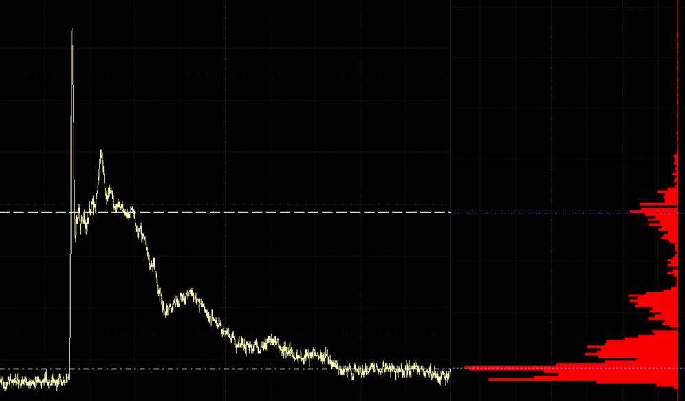
12 Top and Base are not meaningful for ESD pulse measurements What happens when standard pulse parameters are applied to an ESD waveform? Top ESD pulse A voltage level histogram of this ESD pulse does not result in the identification of two main modes. Standard pulse parameters will not yield correct results in this case. Base

13 ESD Top and Base are not meaningful for pulse measurements With Top (100%) and Base (0%) identified in the following locations, the 10%-90% risetime measurement will only encompass a very small portion of the total ESD pulse rising edge Top Base
14 ESD Pulse Rise Time Definitions Require 0% and Max Different than IEEE pulse definitions, EMC pulse definitions (for example the IEC standard) use 0% and Max, instead of Top and Base to calculate 10%-90% risetime An oscilloscope must use 0% and Max thresholds in order to perform the EMC-specific measurement EMC pulse measurements now require the use of thresholds set to 0% and Max (where Max is the peak voltage level of the waveform), instead of Top and Base, to meet the measurement specification. Modern oscilloscopes have begun to allow for EMC pulse parameter measurements using threshold settings of peak-to-peak, 0% to Max, and 0% to Min along with the standard absolute or percent levels.
15 Risetime calculated using standard IEEE pulse parameter definitions Risetime is incorrectly calculated as 494 picoseconds on this ESD pulse. Note the risetime detailed marker location.
16 Risetime calculated using EMC thresholds Max 0% Risetime is correctly calculated as 854 picoseconds on this ESD pulse
17 Effect of thresholds on the Width measurement of this ESD pulse
18 Effect of thresholds on the Width measurement of this ESD pulse
, the thresholds are set to 0% - Max, and the pulse width is measured correctly as 2.109 nanoseconds.")
19 Standard and EMC thresholds for ESD pulse width The pulse width and risetime are measured, both with and without EMC thresholds applied. In parameter 1 (P1), the thresholds are set to 0% - Max, and the pulse width is measured correctly as nanoseconds. In parameter 2 (P2), the thresholds are set to the standard scope threshold of 50% of Top and Base. In this case, the measurement is incorrectly reported as nanoseconds -- an error of 2287%. The width measurement was impacted so significantly, that the 50% threshold between Top and Base actually produced a width measurement on the wrong pulse shape. Parameter 3 (P3) is set to the correct EMC threshold of 0% to Max, producing a correct electrostatic pulse risetime measurement of 833 picoseconds. Notice that in parameter 4 (P4), the standard risetime is incorrectly reported as 873 picoseconds. When using standard pulse parameter measurements, erroneous values can be obtained. Use of standard pulse thresholds produced a 2287% measurement error on this ESD pulse. Note the threshold indicated in the width@level parameter marker for each.
20 EMC Level-At-Pulse, Time-To-Value, Parameter Limiting
21 EMC Level-At-Pulse Parameter
22 EMC Level-At-Pulse Parameter
23 EMC Level-At-Pulse Parameter
24 EMC Time-To-Half Value Parameter
25 Parameter limiting technique for ESD width measurement Because EMC pulses often have pulse perturbations on the falling edge of the pulse, these can result in false measurement readings when using standard parameters. For example, if the falling edge had ringing oscillations which repeatedly crossed the threshold, then multiple false width readings would be possible. For this reason, a measurement filtering capability which can limit the number of pulses the scope measures in an acquisition is needed. This measurement filtering capability, now available on modern scopes, allows for pulse-like perturbations on the falling edge of a pulse to be ignored and excluded from the measurement results. Parameter statistics could be accumulated on the first pulse in conjunction with parameter limiting subsequent perturbations.

26 A Parameter Limiter Is Needed To Avoid Measuring The Bounce Areas As Widths


27 Parameter Limiter Isolates Correct Width
28 ESD Verification Test Setup Example


29 Verification Of The Output Characteristics Of The Test Pulse Generator current shunt target 20 db attenuator connects to current shunt target output double shielded cable leads to 6 db attenuators on input of scope Teledyne LeCroy in cooperation with Hitachi Automotive Systems

30 Verification Of The Output Characteristics Of The Test Pulse Generator Teledyne LeCroy in cooperation with Hitachi Automotive Systems

31 Verification Of The Output Characteristics Of The Test Pulse Generator Teledyne LeCroy in cooperation with Hitachi Automotive Systems

32 Using 0% - Max Thresholds for ESD Rise Time Measurement Teledyne LeCroy in cooperation with Hitachi Automotive Systems
33 Calculating ESD Pulse Maximum (first peak current) Teledyne LeCroy in cooperation with Hitachi Automotive Systems
34 Voltage level calculation at 400 ns delay after 50% incident pulse level (current at t 1 ) Teledyne LeCroy in cooperation with Hitachi Automotive Systems
35 Voltage level calculation at 800 ns delay after 50% incident pulse level (current at t 2 ) Teledyne LeCroy in cooperation with Hitachi Automotive Systems

36 ESD pulse parameters of rise time, first peak current, and currents at t 1 and t 2 First peak current Rise time Current at t 1 Current at t 2 Teledyne LeCroy in cooperation with Hitachi Automotive Systems
37 Sample Rate's Impact On Rise Time For ESD Pulse Measurements

38 Effect of Sample Rate On ESD Rise Time Measurements ESD pulse sampled at 40 GS/s Approximately 50 sample points on rising edge ESD pulse sampled at 4 GS/s Approximately 5-6 sample points on rising edge ESD pulse sampled at 2 GS/s Not enough sample points to correctly characterize rising edge ESD pulse sampled at 1 GS/s Not enough sample points to correctly characterize rising edge


39 Effect of Sample Rate On ESD Rise Time Measurements ESD pulse sampled at 40 GS/s Measured rise time: 839 ps ESD pulse sampled at 4 GS/s Measured rise time: 865 ps (3% measurement error) ESD pulse sampled at 2 GS/s Measured rise time: ns ESD pulse sampled at 1 GS/s Measured rise time < 1.54 ns, and measurement warning is reported

40 Sample Rate Goal for ESD Pulses: Rule Of Thumb: Acquire At Least 10 Sample Points On The Rising Edge 50 sample pts on rising edge 10 sample pts on rising edge Measured risetime result is within one half of one percent (measurement result is within 0.5% of 839 ps)
41 Measurement Method Background: Sparse Math Operator Was Used To Isolate Sample Rate Effect On Same Input Waveform

42 Measurement Method Background: Sparse Math Operator Was Used To Isolate Sample Rate Effect On Same Input Waveform
43 Measurement Method Background: Sparse Math Operator Was Used To Isolate Sample Rate Effect On Same Input Waveform
44 Dynamic Range and Signal Integrity For ESD Pulse Measurements
 available at full scale or 12 vertical bits (4096 ADC levels) available at full")
45 Dynamic Range and Signal Integrity For ESD Pulse Measurements This Concept Holds True for All Digitizing Real Time Scopes 8 vertical bits (256 ADC levels) available at full scale or 12 vertical bits (4096 ADC levels) available at full scale
46 Dynamic Range and Signal Integrity For ESD Pulse Measurements This Concept Holds True for All Digitizing Real Time Scopes 7 vertical bits (128 ADC levels) available at full scale or 11 vertical bits (2048 ADC levels) available at full scale
 available at full scale or 10 vertical bits (1024 ADC levels) available at full")
47 Dynamic Range and Signal Integrity For ESD Pulse Measurements This Concept Holds True for All Digitizing Real Time Scopes 6 vertical bits (64 ADC levels) available at full scale or 10 vertical bits (1024 ADC levels) available at full scale

48 Scope Block Diagram Shows Why Maximizing Waveforms In Grid Maximizes Measurement Accuracy This Concept Holds True for All Digitizing Real Time Scopes
49 Surge Testing
50 Surge Testing General Test Requirements Pulse Characteristics T rise = typically 1.2 to 10 ms T fall = typically 20 to 10,000ms Measurement Needs Rise time Pulse Width Maximum Area Charge

51 A Surge pulse also does not have a clearly-defined Top and Base The pulse characteristics of a surge pulse also do not conform to the IEEE pulse parameter definitions, because the surge does not have high and low steady-state values. After a fast linear rise to a sharp peak, the waveform then exponentially decays toward, but does not quickly reach, an asymptote. With no steady-state values, the surge will produce indeterminate Top and Base values. Because Top and Base must be determined in order to calculate the thresholds used for risetime, falltime, and pulse width, the measurements therefore become invalid when using traditional oscilloscope clock pulse parameters.
52 Hardware Configuration for Surge Verification Teledyne LeCroy in cooperation with Hitachi Automotive Systems

53 Hardware Configuration for Surge Verification Teledyne LeCroy in cooperation with Hitachi Automotive Systems
54 Surge Verification Measurements Including Rise Time, Pulse Width, Maximum, Area, and Charge Teledyne LeCroy in cooperation with Hitachi Automotive Systems
55 Application example: The ISO10605:2008 standard requires the measurement of 10 consecutive parameter values


56 ISO10605:2008 pulse measurement statistics of 10 consecutive acquisitions Teledyne LeCroy in cooperation with Hitachi Automotive Systems


57 Histogram statistical distribution of 10 consecutive acquisitions Teledyne LeCroy in cooperation with Hitachi Automotive Systems
58 Application example: The ISO10605:2001(E) standard (pg 13) requires the measurement of the RC time constant value of the decay of an air discharge ESD pulse. A location is referenced at a stable point on the waveform, then a second point is located at 37% voltage level of the first value. The time difference between the two points is calculated to determine the RC time constant of the decay time.

59 Hardware setup for RC time constant measurement Published: /16/$ IEEE
60 ISO10605:2001(E) RC time constant measurement Published: /16/$ IEEE

61 ISO10605:2001(E) RC time constant measurement Published: /16/$ IEEE

62 ISO10605:2001(E) RC time constant measurement script Published: /16/$ IEEE
 ' waveform sample points array If (app.measure.p1.source1) <> \"F4\" Then ' if the source for P1 isn't F4 app.")
63 Script used to measure the RC Time Constant Set app = CreateObject("LeCroy.XStreamDSO") ' ActiveX COM handle numsamples = InResult1.Samples ' number of sample points in acquisition scaleddata = InResult1.DataArray(True) ' waveform sample points array If (app.measure.p1.source1) <> "F4" Then ' if the source for P1 isn't F4 app.measure.p1.source1 = "F4" ' then set it to F4 app.measure.p1.source2 = "None" ' and set the other input to be blank End If ' Force F4 to be the input source for this script at all times trigpt = app.math.f4.out.result.horizontaloffset ' Determine the trigger point / horizontal offset sampleres = app.math.f4.out.result.horizontalperstep ' Determine the spacing between sample points horzunits = app.math.f4.out.result.horizontalunits ' Query for units (e.g. Seconds, etc.) vertunits = app.math.f4.out.result.verticalunits ' Query for units (e.g. Volts, etc.) x2_array_position = numsamples ' hardcoded value for X2 that placed it on the rightmost graticule on the screen x2_time_position = trigpt + (sampleres * x2_array_position) ' calculate the rightmost falling edge value in terms of time (rather than an array index) e_constant = value from ISO spec i = x2_array_position ' counter position x1_target_value = scaleddata(x2_array_position)/(e_constant) Do While (scaleddata(i) < x1_target_value) And (i > 1) i = i - 1 Loop x1_array_position = i x1_time_position = trigpt + (sampleres * x1_array_position) x1_vertical_position = scaleddata(x1_array_position) x2_vertical_position = scaleddata(x2_array_position) labelsposition = Cstr(x1_time_position) & "," & Cstr(x2_time_position) app.math.f4.viewlabels = True ' turn label display on app.math.f4.labelsposition = labelsposition ' set position of labels app.math.f4.labelstext = "X1" & "," & "X2" ' set text of labels OutResult.VerticalResolution = ' set fine resolution of measurement output (for example, picosecond timing resolution) OutResult.VerticalUnits = "S" ' set horizontal units of measurement to be the same as the horizontal units of the input waveform (e.g. seconds) OutResult.Value = x2_time_position - x1_time_position ' time constant is reported app.measure.p2.operator.value = (x2_vertical_position / x1_vertical_position) app.measure.p1.alias="rc Time Constant" app.measure.p2.alias="y1/y2 ratio" app.measure.p3.alias="y1/y2 percent" Published: /16/$ IEEE
64 Y1/Y2 ratio is computed with a pushed parameter constant value Published: /16/$ IEEE
65 Convert Y1/Y2 to Ratio in Percent Published: /16/$ IEEE
66 ISO10605:2001(E) RC time constant on inverted pulse Published: /16/$ IEEE

67 Trend Plot Shows Data Log of RC Time Constant Values Published: /16/$ IEEE
68 Application example: Voltages Referenced Below Battery Level

69 Battery Voltage Signal From Generator Teledyne LeCroy in cooperation with Hitachi Automotive Systems
70 Method 1 to characterize voltage level: Runt Trigger on individual pulses Teledyne LeCroy in cooperation with Hitachi Automotive Systems
71 Method 1 to characterize voltage level: Runt Trigger on individual pulses Teledyne LeCroy in cooperation with Hitachi Automotive Systems
72 Method 2 to characterize voltage level: Gated Mean Measurement Teledyne LeCroy in cooperation with Hitachi Automotive Systems

73 Method 2 to characterize voltage level: Gated Mean Measurement Teledyne LeCroy in cooperation with Hitachi Automotive Systems

74 Method 2 to characterize voltage level: Gated Mean Measurement Teledyne LeCroy in cooperation with Hitachi Automotive Systems
75 Method 2 to characterize voltage level: Gated Mean Measurement Teledyne LeCroy in cooperation with Hitachi Automotive Systems
76 Dropout and Interrupt Testing Method 1 Runt / Glitch Triggering Can Also Be Used To Capture Dropouts and Interrupts Monitor AC or DC voltage line with oscilloscope during EMC testing Verify that dropout or interrupt occurred, and that device under test was unaffected
77 Electrical Fast Transient (EFT) Testing
78 Transient Testing Pulse Characteristics Capacitive load dump Inductive kickback/spike (back EMF from motor turn off) Measurement Needs Capture Time longer the better: Relay bounce (ms to ms) Transient time ms (motor) ns (FET switch) Measure MHz transient 10s capture = 2Mpts at 100 MHz Sample Rate
79 EFT Testing Electrical Fast Transient Measurement Steps Pulse Characteristics T rise = 5ns T fall = 50ns Burst of many 5x50 pulses Measurement Needs Capture 2ms of burst Measure one pulse, verify shape (rise, fall, width) Measure burst frequency ( khz) Measure Capture time of burst packet (2ms) Measure burst packet rate (300ms)

80 EFT Testing Electrical Fast Transient Measurement Statistics All-instance measurements characterizes all 76 rise times and pulse widths in this EFT burst. EFT bursts can be batch processed to determine EFT pulse characteristics, burst frequency, and packet rate (shown next).
81 Maximizing Acquisition Memory for Events Event occupies 1% of acquisition time Empty space Empty space 100 ns/div

82 Maximizing Acquisition Memory for Events Acquisition time optimized for event 1 ns/div
83 Maximizing Acquisition Memory for Events Mosaic of events is acquired while optimizing acquisition memory, and displayed without empty spaces between events

84 Maximizing Acquisition Memory for Events Mosaic of events is acquired while optimizing acquisition memory, and displayed without empty spaces between events Individual timestamps for each event listed with segment acquisition time and intersegment time. This will automatically measure the EFT burst packet rate.

85 EFT Testing Electrical Fast Transient Sequence Mode and Octal Grid Sequenced acquisition of 5 EFT bursts Zoom of EFT pulses Zoom of one EFT burst Zoom of EFT pulses Zoom of one EFT pulse Zoom of one EFT pulse Zoom of one EFT pulse FFT

86 Individual EFT Pulses Teledyne LeCroy in cooperation with Hitachi Automotive Systems
87 One EFT Burst - Acquired at 2.5 GS/s - note linear top of burst Teledyne LeCroy in cooperation with Hitachi Automotive Systems
88 One EFT Burst - Acquired at 125 MS/s - note amplitude distortion at top of burst Teledyne LeCroy in cooperation with Hitachi Automotive Systems
89 Comparison of one EFT burst captured at 1.25 GS/s and 125 MS/s 125 MS/s 2.5 GS/s Teledyne LeCroy in cooperation with Hitachi Automotive Systems
90 Effect of Sample Rate on EFT Pulse Capture Sampled at 100 MS/s vs GS/s 100 MS/s 2.5 GS/s Teledyne LeCroy in cooperation with Hitachi Automotive Systems
91 Frequency measurement parameter measures only values in the range between 9kHz and 11kHz Teledyne LeCroy in cooperation with Hitachi Automotive Systems
92 Negative width parameter calculates gap time with values in range Teledyne LeCroy in cooperation with Hitachi Automotive Systems
93 EFT Rise Time With 0-Max Thresholds Teledyne LeCroy in cooperation with Hitachi Automotive Systems
 Teledyne LeCroy in cooperation with Hitachi Automotive")
94 Note the difference between P2 Width (gap time) and P4 Width (EFT pulse width) Teledyne LeCroy in cooperation with Hitachi Automotive Systems

95 EFT Max, Area, and Energy Calculations Teledyne LeCroy in cooperation with Hitachi Automotive Systems
96 Electrical Fast Transient (EFT) Debugging Techniques Using Segmented Memory

97 20 EFT Bursts Captured Using Segmented Memory Teledyne LeCroy in cooperation with Hitachi Automotive Systems
98 Inter-burst EFT Timestamps Teledyne LeCroy in cooperation with Hitachi Automotive Systems
99 Inter-pulse EFT Timestamps: Individual EFT pulses in segmented memory Teledyne LeCroy in cooperation with Hitachi Automotive Systems

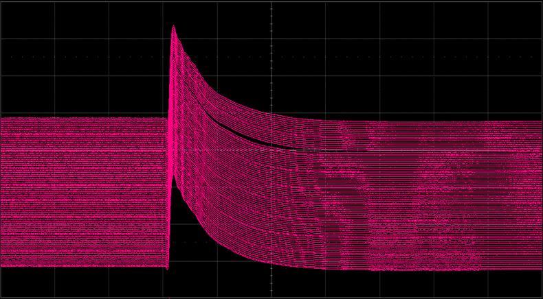
100 Overlay And Waterfall Of EFT Pulses Verifies Correct EFT Pulse Shape Characteristics Teledyne LeCroy in cooperation with Hitachi Automotive Systems

101 Segmented Overlay And Waterfall Of EFT Pulses Highlights Anomalies Reveals Possible Bad Contact Within The Transient Simulator Teledyne LeCroy in cooperation with Hitachi Automotive Systems
102 MIL-STD-461G Department of Defense Requirements for the Control of Electromagnetic Interference Characteristics of Subsystems and Equipment

103 MIL-STD-461G CS117 and CS118 are new with the G version of the standard specification Applicable to a wide variety of DoD systems CS117: Lightning strike testing CS118: ESD testing This requirement is applicable to all aircraft safety-critical equipment interconnecting cables, including complete power cables, and individual high side power leads. It is also applicable to non-safety critical equipment with interconnecting cables/electrical interfaces that are part of or connected to equipment performing safety critical functions. It may be applicable to aircraft equipment performing nonsafety critical functions when specified by the procuring activity. This requirement applies to surface ship equipment which is located above deck or has interconnecting cables which are routed above deck.

104 MIL-STD-461G CS116 damped sinusoid measurement
105 MIL-STD-461G EMC level-at-pulse and half life measurements
106 MIL-STD-461G multiple stroke and multiple burst lightning strike test
107 Surge Test example computing Rise Time, Pulse Width, Maximum, Area, and Charge
108 EMC - Radiated Immunity Testing
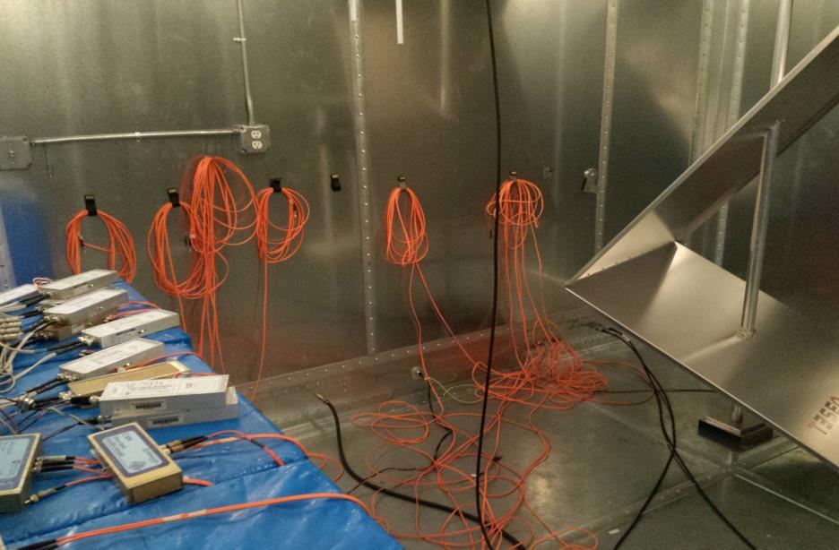
109 Radiated Immunity Testing - Real Time Functional Performance Evaluation Deviation detection of a device under test (DUT) during exposure to a disturbance Functional state of the DUT is output through non-conductive fiber optic cables Mechanical mode tuner Devices under test are exposed to electric fields high enough to effect operation of nonshielded equipment. Transmit and receive antennas generate a controlled electric field RF-hardened fiber optic transmitters Teledyne LeCroy in cooperation with Hitachi Automotive Systems


110 Outside the reverberant chamber, oscilloscope masks test for acceptance criteria Optical receiver and O/E converter 16 channels performing mask test criteria such as signal high level, signal low level, frequency, duty cycle, and other criteria fit within tolerance limits described in the test plan Teledyne LeCroy in cooperation with Hitachi Automotive Systems

111 Views from inside and outside of the reverberant chamber Teledyne LeCroy in cooperation with Hitachi Automotive Systems

112 Simulated ECU (Electronic Control Unit) outputs: Two PWM outputs, a driver actuator signal, and a CAN split signal Teledyne LeCroy in cooperation with Hitachi Automotive Systems

113 Mask testing ECU outputs: example with passing results Teledyne LeCroy in cooperation with Hitachi Automotive Systems
114 Mask testing ECU outputs exceeding the tolerance mask criteria Teledyne LeCroy in cooperation with Hitachi Automotive Systems

115 Special Thanks To: Special thanks to Hitachi Automotive Systems (an ISO accredited lab) for providing access to EMC test setups, equipment, expertise and insight. Teledyne LeCroy in cooperation with Hitachi Automotive Systems
116 Questions?
EMC Pulse Measurements
 EMC Pulse Measurements and Custom Thresholding Presented to the Long Island/NY IEEE Electromagnetic Compatibility and Instrumentation & Measurement Societies - May 13, 2008 Surge ESD EFT Contents EMC measurement
Switched Mode Power Supply Measurements
 Power Analysis 1 Switched Mode Power Supply Measurements AC Input Power measurements Safe operating area Harmonics and compliance Efficiency Switching Transistor Losses Measurement challenges Transformer
Measurement and Analysis for Switchmode Power Design
 Measurement and Analysis for Switchmode Power Design Switched Mode Power Supply Measurements AC Input Power measurements Safe operating area Harmonics and compliance Efficiency Switching Transistor Losses
CHAPTER 6 EMI EMC MEASUREMENTS AND STANDARDS FOR TRACKED VEHICLES (MIL APPLICATION)
") 147 CHAPTER 6 EMI EMC MEASUREMENTS AND STANDARDS FOR TRACKED VEHICLES (MIL APPLICATION) 6.1 INTRODUCTION The electrical and electronic devices, circuits and systems are capable of emitting the electromagnetic
147 CHAPTER 6 EMI EMC MEASUREMENTS AND STANDARDS FOR TRACKED VEHICLES (MIL APPLICATION) 6.1 INTRODUCTION The electrical and electronic devices, circuits and systems are capable of emitting the electromagnetic
EMC standards. Presented by: Karim Loukil & Kaïs Siala
 Training Course on Conformity and Interoperability on Type Approval testing for Mobile Terminals, Homologation Procedures and Market Surveillance, Tunis-Tunisia, from 20 to 24 April 2015 EMC standards
Immunity Testing for the CE Mark
 Immunity Testing for the CE Mark Summary The European Union (EU) currently has 25 member countries with 2 additional countries to be added in 2007. The total population at that time will be nearly a half
Appendix A: Specifications
 All specifications apply to the TDS 200-Series Digital Oscilloscopes and a P2100 probe with the Attenuation switch set to 10X unless noted otherwise. To meet specifications, two conditions must first be
Harmonizing the ANSI-C12.1(2008) EMC Tests. Harmonizing the ANSI-C12.1(2008) EMC Tests
 EMC Tests. Harmonizing the ANSI-C12.1(2008) EMC Tests") Harmonizing the ANSI-C12.1(2008) EMC Tests Subcommittee 1 (Emissions) Subcommittee 5 (Immunity) Joint Task Force on C12.1 June 17, 2013 1 The Accredited Standards Committee C63 presents Harmonizing the
Harmonizing the ANSI-C12.1(2008) EMC Tests Subcommittee 1 (Emissions) Subcommittee 5 (Immunity) Joint Task Force on C12.1 June 17, 2013 1 The Accredited Standards Committee C63 presents Harmonizing the
Advanced Test Equipment Rentals ATEC (2832)
") Established 1981 Advanced Test Equipment Rentals www.atecorp.com 800-404-ATEC (2832) Downloaded from http://www.everyspec.com DEPARTMENT OF DEFENSE INTERFACE STANDARD METRIC 22 MARCH 2013 SUPERSEDING MIL-STD-1275D
Established 1981 Advanced Test Equipment Rentals www.atecorp.com 800-404-ATEC (2832) Downloaded from http://www.everyspec.com DEPARTMENT OF DEFENSE INTERFACE STANDARD METRIC 22 MARCH 2013 SUPERSEDING MIL-STD-1275D
A Comparison Between MIL-STD and Commercial EMC Requirements Part 2. By Vincent W. Greb President, EMC Integrity, Inc.
 A Comparison Between MIL-STD and Commercial EMC Requirements Part 2 By Vincent W. Greb President, EMC Integrity, Inc. OVERVIEW Compare and contrast military (i.e., MIL-STD) and commercial EMC immunity
2620 Modular Measurement and Control System
 European Union (EU) Council Directive 89/336/EEC Electromagnetic Compatibility (EMC) Test Report 2620 Modular Measurement and Control System Sensoray March 31, 2006 April 4, 2006 Tests Conducted by: ElectroMagnetic
An Introduction to EMC Testing (what can be done with scopes) Vincent Lascoste EMC Product Manager - RSF
 Vincent Lascoste EMC Product Manager - RSF") An Introduction to EMC Testing (what can be done with scopes) Vincent Lascoste EMC Product Manager - RSF Definition of ElectroMagnetic Compatibility (EMC) EMC is defined as: "The ability of devices and
An Introduction to EMC Testing (what can be done with scopes) Vincent Lascoste EMC Product Manager - RSF Definition of ElectroMagnetic Compatibility (EMC) EMC is defined as: "The ability of devices and
Test and Measurement for EMC
 Test and Measurement for EMC Bogdan Adamczyk, Ph.D., in.c.e. Professor of Engineering Director of the Electromagnetic Compatibility Center Grand Valley State University, Michigan, USA Ottawa, Canada July
Scale Manufacturers Association (SMA) Recommendation on. Electrical Disturbance
 Recommendation on. Electrical Disturbance") Scale Manufacturers Association (SMA) Recommendation on Electrical Disturbance (SMA RED-0499) Provisional First Edition Approved by SMA Pending Final Comment April 24, 1999 Copyright: SMA, April, 1999
Scale Manufacturers Association (SMA) Recommendation on Electrical Disturbance (SMA RED-0499) Provisional First Edition Approved by SMA Pending Final Comment April 24, 1999 Copyright: SMA, April, 1999
Understanding Design, Installation, and Testing Methods That Promote Substation IED Resiliency for High-Altitude Electromagnetic Pulse Events
 Understanding Design, Installation, and Testing Methods That Promote Substation IED Resiliency for High-Altitude Electromagnetic Pulse Events Tim Minteer, Travis Mooney, Sharla Artz, and David E. Whitehead
N acquisitions, all channels simultaneously, N is selectable from 4, 16, 64, and 128 Inputs
 With compliments All specifications apply to the TDS 200-Series Digital Real-Time Oscilloscope with a P2100 probe with the Attenuation switch set to 10X unless noted otherwise. To meet specifications,
Contents. 1 Introduction. 2 System-Level Electrostatic Discharge (ESD) and Electrical Fast Transient. 3 Electromagnetic Interference
 and Electrical Fast Transient. 3 Electromagnetic Interference") Issue 3, October 2002 Electromagnetic Compatibility and Electrical Safety Contents Telcordia GR-1089 - Documentation Information Generic Requirements Notice Of Disclaimer................. iii Contents.......................................
Issue 3, October 2002 Electromagnetic Compatibility and Electrical Safety Contents Telcordia GR-1089 - Documentation Information Generic Requirements Notice Of Disclaimer................. iii Contents.......................................
MIL Standard 461 G. final release December 11 th, EMC PARTNER - Largest range of impulse test equipment up to 100kV and 100kA
 MIL Standard 461 G final release December 11 th, 2015 EMC PARTNER - Largest range of impulse test equipment up to 100kV and 100kA CDN-UTP8 Ed. 3 - Universal The Swiss CDN company for data EMC and telecom
Table of Contents. 1 Introduction. 2 System-Level Electrostatic Discharge (ESD) and Electrical Fast Transient (EFT) 3 Electromagnetic Interference
 and Electrical Fast Transient (EFT) 3 Electromagnetic Interference") Electromagnetic Compatibility and Electrical Safety GR-1089-CORE Table of Contents Table of Contents 1 Introduction 1.1 Purpose and Scope.................................. 1 1 1.2 Items Not Covered in
Electromagnetic Compatibility and Electrical Safety GR-1089-CORE Table of Contents Table of Contents 1 Introduction 1.1 Purpose and Scope.................................. 1 1 1.2 Items Not Covered in
Mil Std 461E CS-115 CS-115 MIL STD 461E CS-115 CS-116 RS-105
 Mil Std 461E CS-115 CS-116 RS-105 Bruce Harlacher Fischer Custom Communications, Inc. MIL STD 461E CS-115 CS-116 RS-105 Purpose of Test History Type of Test What Is To Be Tested Calibration Setup Calibration
DRAFT REGULATORY GUIDE DG-1029
 123-0079.htm at ruleforum.llnl.gov Page 1 of 31 U.S. NUCLEAR REGULATORY COMMISSION February 1998 OFFICE OF NUCLEAR REGULATORY RESEARCH Division 1 Draft DG-1029 DRAFT REGULATORY GUIDE Contact: C.E. Antonescu
One-day Conference 18 March Power Supply, EMC and Signalling, in Railway Systems
 One-day Conference 18 March 2017 Power Supply, EMC and Signalling, in Railway Systems EMC Management and Related Technical Aspects in Railway Systems By Dr Peter S W LEUNG http://www.ee.cityu.edu.hk/~pswleung/
LeCroy 9304A, 9304AM Digital Oscilloscopes 200 MHz Bandwidth, 100 MS/s. Main Features
 LeCroy 9304A, 9304AM Digital Oscilloscopes 200 MHz Bandwidth, 100 MS/s Main Features Four Channels 50k and 200k Point Records DOS Compatible Floppy Disk, PCMCIA portable hard drive and Memory Card Options
EN61326 EMC COMPLIANCE REPORT on the LP Series Ultrasonic Transmitter Remote Amplifier and Transducer for Hawk Measurement Systems Pty Ltd
 Page 1 of 15 EMC Technologies Pty Ltd ABN 82 057 105 549 57 Assembly Drive Tullamarine Victoria Australia 3043 Ph: + 613 9335 3333 Fax: + 613 9338 9260 email: melb@emctech.com.au EN61326 EMC COMPLIANCE
FISCHER CUSTOM COMMUNICATIONS, INC.
 FISCHER CUSTOM COMMUNICATIONS, INC. Current Probe Catalog FISCHER CUSTOM COMMUNICATIONS, INC. Fischer Custom Communications, Inc., is a manufacturer of custom electric and magnetic field sensors for military
Downloaded from 1. THE FOLLOWING PAGES OF MIL-STD-462D HAVE BEEN REVISED AND SUPERSEDE THE PAGES LISTED:
 NOTICE OF CHANGE METRIC 10 April 1995 MILITARY STANDARD MEASUREMENT OF ELECTROMAGNETIC INTERFERENCE CHARACTERISTICS TO ALL HOLDERS OF : 1. THE FOLLOWING PAGES OF HAVE BEEN REVISED AND SUPERSEDE THE PAGES
Schedule of Accreditation issued by United Kingdom Accreditation Service 2 Pine Trees, Chertsey Lane, Staines-upon-Thames, TW18 3HR, UK
 2 Pine Trees, Chertsey Lane, Staines-upon-Thames, TW18 3HR, UK Caddsdown Industrial Estate Clovelly Road Bideford Devon EX39 3DX Contact: Becky Scott Tel: +44 (0)1237 423388 Fax: +44 (0)1237 423434 E-Mail:
BS EN TESTS ON THE IT TOXIC GAS DETECTOR MODULE
 Page 1 of 18 Interference Testing And Consultancy Services (Pty) Ltd ITC SERVICES (PTY) LTD Reg 88/002032/07 Plot 44 Kameeldrift East, Pretoria Private Bag X13 Lynn East 0039 Republic of South Africa Tel
EMC TEST REPORT For MPP SOLAR INC Inverter/ Charger Model Number : PIP 4048HS
 EMC-E20130903E EMC TEST REPORT For MPP SOLAR INC Inverter/ Charger Model Number : PIP 4048HS Prepared for : MPP SOLAR INC Address : 4F, NO. 50-1, SECTION 1, HSIN-SHENG S. RD. TAIPEI, TAIWAN Prepared by
~W~~~ Laboratory Accreditation Program
 ~ ~.en) National Voluntary ~W~~~ Laboratory Accreditation Program SCOPE OF ACCREDITATION TO ISO/IEC 17025:2005 Dayton T. Brown, Inc. 1195 Church Street Bohemia, NY 11716 Ms. Mary Alice Der Aris Phone:
Overview of EMC Regulations and Testing. Prof. Tzong-Lin Wu Department of Electrical Engineering National Taiwan University
 Overview of EMC Regulations and Testing Prof. Tzong-Lin Wu Department of Electrical Engineering National Taiwan University What is EMC Electro-Magnetic Compatibility ( 電磁相容 ) EMC EMI (Interference) Conducted
Rohde & Schwarz EMI/EMC debugging with modern oscilloscope. Ing. Leonardo Nanetti Rohde&Schwarz
 Rohde & Schwarz EMI/EMC debugging with modern oscilloscope Ing. Leonardo Nanetti Rohde&Schwarz EMI debugging Agenda l The basics l l l l The idea of EMI debugging How is it done? Application example What
Digital Debug With Oscilloscopes Lab Experiment
 Digital Debug With Oscilloscopes A collection of lab exercises to introduce you to digital debugging techniques with a digital oscilloscope. Revision 1.0 Page 1 of 23 Revision 1.0 Page 2 of 23 Copyright
TEST REPORT FROM RADIO FREQUENCY INVESTIGATION LTD.
 TEST REPORT FROM RADIO FREQUENCY INVESTIGATION LTD. Test Of: Wood & Douglas Ltd ST500 Transmitter Test Report Serial No: RFI/EMCB2/RP39403B This Test Report supersedes RFI Test Report No.: RFI/EMCB1/RP39403B
EN 55015: 2013 Clause Pass. EN 55015: 2013 Clause Pass. EN 55015: 2013 Clause Pass
 Reference No.: WTD15S0730643E Page 2 of 42 1 Test Summary Test Item Conducted Disturbance at Mains Terminal, 9kHz to 30MHz Radiation electromagnetic disturbance, 9kHz to 30MHz Radiation Emission, 30MHz
Test Specification for Type Approval
 A2 (1991) (Rev.1 1993) (Rev.2 1997) (Rev. 2.1 July 1999) (Rev.3 May 2001) (Corr.1 July 2003) (Rev.4 May 2004) (Rev.5 Dec 2006) (Rev.6 Oct 2014) Test Specification for Type Approval.1 General This Test
System description 4. SERVICES ONSITE INSTALLATION AND TRAINING SYSTEM ACCEPTANCE MAINTENANCE... 7
 Ultra Wide Band test setup System description 1. UWB TEST SYSTEM DESCRIPTION... 2 2. SYSTEM MONITORING... 5 3. OTHER MEASUREMENT SYSTEMS & ACCESSORIES... 6 3.1 OSCILLOSCOPE & SHIELDED ENCLOSURE... 6 3.2
Schlöder GmbH - EMC Test and Measurement Systems Model #
 Schlöder GmbH - EMC Test and Measurement Systems Model # Product Description IEC / EN 61000-4 - 2 ESD SESD 216 ESD generator 10 kv CON / 16,5 kv AIR acc. to IEC 61000-4-2, 150 pf / 330 ohm SESD 230 ESD
LeCroy 9384 Series Digital Oscilloscope 1 GHz Bandwidth, 1-4 GS/s
 LeCroy 9384 Series Digital Oscilloscope 1 GHz Bandwidth, 1-4 GS/s Main Features 1 GHz Bandwidth Sample rates to 4 Gigasamples/second Memory lengths to 8M points 8-bit vertical resolution, 11 with ERES
Future In Radiated Immunity Testing
 Future In Radiated Immunity Testing Flynn Lawrence Flynn Lawrence is an Applications Engineer for AR RF/Microwave Instrumentation. At AR, Flynn is actively engaged in new application and product development
TEST REPORT... 1 CONTENT...
 CONTENT TEST REPORT... 1 CONTENT... 2 1 TEST RESULTS SUMMARY... 3 2 EMC RESULTS CONCLUSION... 4 3 LABORATORY MEASUREMENTS... 6 4 EMI TEST... 7 4.1 CONTINUOUS CONDUCTED DISTURBANCE VOLTAGE TEST... 7 4.2
This annex is valid from: to Replaces annex dated: Locations where activities are performed under accreditation
 Annex to declaration accreditation (scope accreditation) Locations where activities are performed under accreditation Location Abbreviation/ location code Head Location Vijzelmolenlaan 5 & 7 3447 GX oerden
Techniques to reduce electromagnetic noise produced by wired electronic devices
 Rok / Year: Svazek / Volume: Číslo / Number: Jazyk / Language 2016 18 5 EN Techniques to reduce electromagnetic noise produced by wired electronic devices - Tomáš Chvátal xchvat02@stud.feec.vutbr.cz Faculty
Partners for HV and EMC Solutions MIL-STD-461 G. Partners for HV and EMC Solutions
 MIL-STD-461 G 1 MIL-STD-461 G 2 MIL-STD-461 G 2015 Current Version Superseding Back Ground MIL-STD-461F (2007) MIL-STD-461E (1999) Test Methods and Limits MIL-STD-461D (1993) Test Limits MIL-STD-462D (1993)
EMC Seminar Series All about EMC Testing and Measurement Seminar 1
 EMC Seminar Series All about EMC Testing and Measurement Seminar 1 Introduction to EMC Conducted Immunity Jeffrey Tsang Organized by : Department of Electronic Engineering 1 Basic Immunity Standards: IEC
Surge Generator for MIL-STD 1275
 Surge Generator for MIL-STD 1275 This generator PG1275 is specially designed for the test of the susceptibility to surges and spikes of military 28 Vdc electric circuits. The equipment allows performing
Transient Data Acquisition System, TAS 4-40 Potential-free measurement of fast rise pulses:
 Transient Data Acquisition System, TAS 4-40 Potential-free measurement of fast rise pulses: High precision measurement of fast rising voltages and currents causes considerable problems in many spheres
EN 55022: 2010+AC:2011 Clause 6.1 Pass. Harmonic Current EN :2006+A1:2009+A2:2009 Class A N/A
 Reference No.: WT12106773-N-S-E Page 2 of 33 1 Test Summary Test Item Mains Terminal Disturbance Voltage, 150KHz to 30MHz Radiation Emission, 30MHz to 1000MHz EMISSION Test Standard Class / Severity Result
Combination Wave Test System
 Immunity Tests Combination Wave Test System Brief Overview of Phenomena............... 2 Applicable Standards................... 3 Test System Overview.................. 4 Generator Specifications.................
Test Plan for Hearing Aid Compatibility
 Test Plan for Hearing Aid Compatibility Version Number 3.1 February 2017 2017 CTIA - The Wireless Association. All rights reserved. CTIA hereby grants to CTIA Authorized Testing Laboratories (CATLs), and
Contents. ZT530PCI & PXI Specifications. Arbitrary Waveform Generator. 16-bit, 400 MS/s, 2 Ch
 ZT530PCI & PXI Specifications Arbitrary Waveform Generator 16-bit, 400 MS/s, 2 Ch Contents Outputs... 2 Digital-to-Analog Converter (DAC)... 3 Internal DAC Clock... 3 Spectral Purity... 3 External DAC
MAKING TRANSIENT ANTENNA MEASUREMENTS
 MAKING TRANSIENT ANTENNA MEASUREMENTS Roger Dygert, Steven R. Nichols MI Technologies, 1125 Satellite Boulevard, Suite 100 Suwanee, GA 30024-4629 ABSTRACT In addition to steady state performance, antennas
Keysight Technologies Essential Capabilities of EMI Receivers. Application Note
 Keysight Technologies Essential Capabilities of EMI Receivers Application Note Contents Introduction... 3 CISPR 16-1-1 Compliance... 3 MIL-STD-461 Compliance... 4 Important features not required by CISPR
Jitter Analysis Techniques Using an Agilent Infiniium Oscilloscope
 Jitter Analysis Techniques Using an Agilent Infiniium Oscilloscope Product Note Table of Contents Introduction........................ 1 Jitter Fundamentals................. 1 Jitter Measurement Techniques......
Correct Measurement of Timing and Synchronisation Signals - A Comprehensive Guide
 Correct Measurement of Timing and Synchronisation Signals - A Comprehensive Guide Introduction This document introduces the fundamental aspects of making valid timing and synchronisation measurements and
Harmonic Current emission EN :2014 Class A Pass. Voltage Fluctuation and Flicker EN :2013 Clause 5 Pass
 Reference No.: WTS15F0323845E Page 2 of 33 1 Test Summary Test Item Mains Terminal Disturbance Voltage, 148.5kHz to 30MHz Disturbance Power, 30MHz to 300MHz Discontinuous Disturbance (Click) Radiated Emission,
Testing Sensors & Actors Using Digital Oscilloscopes
 Testing Sensors & Actors Using Digital Oscilloscopes APPLICATION BRIEF February 14, 2012 Dr. Michael Lauterbach & Arthur Pini Summary Sensors and actors are used in a wide variety of electronic products
Analogue circuit design for RF immunity
 Analogue circuit design for RF immunity By EurIng Keith Armstrong, C.Eng, FIET, SMIEEE, www.cherryclough.com First published in The EMC Journal, Issue 84, September 2009, pp 28-32, www.theemcjournal.com
Discontinuous Disturbance (Click) EN :2006+A1:2009+A2:2011 Clause N/A** Radiated Emission, 30MHz to 1000MHz
 EN :2006+A1:2009+A2:2011 Clause N/A** Radiated Emission, 30MHz to 1000MHz") Reference No.: WTN13F0706038E Page 2 of 40 1 Test Summary Test Item Mains Terminal Disturbance Voltage, 148.5kHz to 30MHz Disturbance Power, 30MHz to 300MHz EMISSION Test Standard Class / Severity Result
Reference No.: WTN13F0706038E Page 2 of 40 1 Test Summary Test Item Mains Terminal Disturbance Voltage, 148.5kHz to 30MHz Disturbance Power, 30MHz to 300MHz EMISSION Test Standard Class / Severity Result
2 Operation. Operation. Getting Started
 2 Operation Operation Getting Started Access the Ethernet Package by pressing the ANALYSIS PACKAGES button (MATH on LC scopes). A menu showing all the packages installed on the DSO is displayed. Select
High precision measurement system for current and voltage IHC-A/B-RM01/03
 Measurement Offset-free and low-noise 16 bit data acquisition system ISA-ASIC Internal sample rate 3,500 Hz Communication Standard RS232- or RS485 interface Advantages Direct measurement on the bus bar
Advanced Test Equipment Rentals ATEC (2832)
") Established 1981 Advanced Test Equipment Rentals www.atecorp.com 800-404-ATEC (2832) Page 1 of 8 9350A Family Digital Oscilloscopes 500 MHz Bandwidth, 2 GS/s Main Features Two and Four Channel versions
Established 1981 Advanced Test Equipment Rentals www.atecorp.com 800-404-ATEC (2832) Page 1 of 8 9350A Family Digital Oscilloscopes 500 MHz Bandwidth, 2 GS/s Main Features Two and Four Channel versions
WaveAce 1000 and 2000 Oscilloscopes
 1000 and 2000 Oscilloscopes 40 MHz 300 MHz Key Features Sample rates up to 2 GS/s 1 Mpts/ch memory, 2 Mpts interleaved 7" color display on all models 32 automatic measurements Multi-language user interface
9 Specifications. Specifications NOMINAL CHARACTERISTICS
 9 Specifications Specifications NOMINAL CHARACTERISTICS WARRANTED CHARACTERISTICS Nominal characteristics describe parameters and attributes that are guaranteed by design, but do not have associated tolerances.
Notes on OR Data Math Function
 A Notes on OR Data Math Function The ORDATA math function can accept as input either unequalized or already equalized data, and produce: RF (input): just a copy of the input waveform. Equalized: If the
What the LSA1000 Does and How
 2 About the LSA1000 What the LSA1000 Does and How The LSA1000 is an ideal instrument for capturing, digitizing and analyzing high-speed electronic signals. Moreover, it has been optimized for system-integration
Application Note 5044
 HBCU-5710R 1000BASE-T Small Form Pluggable Low Voltage (3.3V) Electrical Transceiver over Category 5 Unshielded Twisted Pair Cable Characterization Report Application Note 5044 Summary The Physical Medium
EMC Test report for LED Panel Light Models , , , , ,
 4326247.50 EMC Test report for LED Panel Light Models 000529, 000530, 000531, 000532, 000535, 000536 Guangzhou, date of issue: 2016-02-24 Author:Jazz Liang By order of Marvo Verlichting B.V. at Hoogeveen,
Surge Coupling Decoupling Network (S-CDN) Considerations
 Considerations") Surge Coupling Decoupling Network (S-CDN) Considerations Introduction Surge Coupling-Decoupling Networks (SCDN) are used to couple the surge specified in IEC 61000-4-5 onto active telecom lines to determine
Surge Coupling Decoupling Network (S-CDN) Considerations Introduction Surge Coupling-Decoupling Networks (SCDN) are used to couple the surge specified in IEC 61000-4-5 onto active telecom lines to determine
CS114 + CS115 + CS116
 System description Test Setup for MIL-STD-461 D, E&F CS114 + CS115 + CS116 1. MONTENA EMC... 2 1.1 PRODUCTS... 3 1.2 TURN KEY MIL STD 461 TEST INSTALLATIONS... 3 2. TEST SETUP DESCRIPTION... 4 2.1 TEST
Immunity Test System RIS 3000 / RIS 6000 acc. to IEC/EN
 Description The setup of a radiated immunity test system can be done in the conventional way with many separate instruments or in a more comfortable and less risky way with our new EMC control unit, type
For the National Voluntary Laboratory Accreditation Program
 SCOPE OF ACCREDITATION TO ISO/IEC 17025:2005 Intertek Japan K.K. Calibration Laboratory 3-2 Sunayama Kamisu Ibaraki 314-0255 JAPAN Ms. Masako Oyamada Phone: 81-465 89 2316 Fax: 81-465 89 2160 E-mail: masako.oyamada@intertek.com
Voltage Transient Emission Test
 Manual For Operation AN 200 Series Voltage Transient Emission Test AN 200 AN 200B The AN 200 is used to evaluate automotive electrical and electronic components for conducted emissions of transients along
DTE Power via MDI Task Force P802.3af
 DTE Power via MDI Task Force P802.3af AC Disconnect Detection Ad Hoc EN55024 Test Results A.1.4.3 Paul Scott, Norbert Kukta, Scott Burton 10 May 2002 Objectives Determine which EN55024 tests are relevant
Signal and Noise Measurement Techniques Using Magnetic Field Probes
 Signal and Noise Measurement Techniques Using Magnetic Field Probes Abstract: Magnetic loops have long been used by EMC personnel to sniff out sources of emissions in circuits and equipment. Additional
MSO Supplied with a full SDK including example programs Software compatible with Windows XP, Windows Vista and Windows 7 Free Technical Support
 PicoScope 2205 MSO USB-POWERED MIXED SIGNAL OSCILLOSCOPE Think logically... 25 MHz analog bandwidth 100 MHz max. digital input frequency 200 MS/s mixed signal sampling Advanced digital triggers SDK and
DIGITAL OSCILLOSCOPES & DIGITAL SCOPES
 7004 Digital Oscilloscopes DL4100 (700430) 38 220 427mm 15kg ( 15-11/16 8-11/16 16-7/8" 33.1 lbs) YOKOGAWA introduces a brand new digital oscilloscope with outstanding performance. The DL4100 / DL4200
TEST REPORT. Power Spout PLT V. tested to the specification
 EMC Technologies (NZ) Ltd PO Box 68-307 Newton, Auckland 1145 New Zealand Phone 09 360 0862 Fax 09 360 0861 E-Mail Address: aucklab@ihug.co.nz Web Site: www.emctech.com.au TEST REPORT Power Spout PLT 100
M Hewitson, K Koetter, H Ward. May 20, 2003
 A report on DAQ timing for GEO 6 M Hewitson, K Koetter, H Ward May, Introduction The following document describes tests done to try and validate the timing accuracy of GEO s DAQ system. Tests were done
Training Course on Conformity and Interoperability, Tunis-Tunisia, from 14 to 18 December EMC standards
 Training Course on Conformity and Interoperability, Tunis-Tunisia, from 14 to 18 December 2015 EMC standards Presented by: Karim Loukil & Kaïs Siala Kaim.wakil@cert.mincom.tn Kais.siala@cert.mincom.tn
Debugging EMI Using a Digital Oscilloscope. Dave Rishavy Product Manager - Oscilloscopes
 Debugging EMI Using a Digital Oscilloscope Dave Rishavy Product Manager - Oscilloscopes 06/2009 Nov 2010 Fundamentals Scope Seminar of DSOs Signal Fidelity 1 1 1 Debugging EMI Using a Digital Oscilloscope
Training Course on Conformity and Interoperability, Tunis-Tunisia, from 11 to 15 April EMC standards
 Training Course on Conformity and Interoperability, Tunis-Tunisia, from 11 to 15 April 2016 EMC standards Presented by: Karim Loukil & Kaïs Siala Karim.wakil@cert.mincom.tn Kais.siala@cert.mincom.tn Page
BS EN TESTS ON THE RS-485 FFP2 THE BRAIN REVISION C
 Page 1 of 23 Interference Testing And Consultancy Services (Pty) Ltd ITC SERVICES (PTY) LTD Reg 88/002032/07 Plot 44 Kameeldrift East, Pretoria Private Bag X13 Lynn East 0039 Republic of South Africa Tel
Combinational logic: Breadboard adders
 ! ENEE 245: Digital Circuits & Systems Lab Lab 1 Combinational logic: Breadboard adders ENEE 245: Digital Circuits and Systems Laboratory Lab 1 Objectives The objectives of this laboratory are the following:
EMC Test Report. Report Number: M030826
 Page 1 of 36 EMC Technologies Pty Ltd ABN 82 057 105 549 57 Assembly Drive Tullamarine Victoria Australia 3043 Ph: + 613 9335 3333 Fax: + 613 9338 9260 email: melb@emctech.com.au EMC Test Report Report
EMC aspects associated to 5G networks
 EMC aspects associated to 5G networks ETSI TC-EE/ITU-T SG5 Workshop on Towards Setting Environmental Requirements for 5G Beniamino Gorini 23-11-2017 1 Outline 1. Scenario of present EMC requirements 2.
DesignCon Noise Injection for Design Analysis and Debugging
 DesignCon 2009 Noise Injection for Design Analysis and Debugging Douglas C. Smith, D. C. Smith Consultants [Email: doug@dsmith.org, Tel: 408-356-4186] Copyright! 2009 Abstract Troubleshooting PCB and system
E M C T E S T Y O U R SOURCE FOR TOP Q U A L I T Y TEST EQUIPMENT & E M C. w w w. h v t e c h n o l o g i e s. c o m
 E M C T E S T S O L U T I O N S P A R T N E R S F O R H V & E M C S O L U T I O N S Y O U R SOURCE FOR TOP Q U A L I T Y TEST EQUIPMENT w w w. h v t e c h n o l o g i e s. c o m Transient Immunity Generators
Measuring Power Supply Switching Loss with an Oscilloscope
 Measuring Power Supply Switching Loss with an Oscilloscope Our thanks to Tektronix for allowing us to reprint the following. Ideally, the switching device is either on or off like a light switch, and instantaneously
DS 6000 Specifications
 DS 6000 Specifications All the specifications are guaranteed except the parameters marked with Typical and the oscilloscope needs to operate for more than 30 minutes under the specified operation temperature.
This annex is valid from: to Replaces annex dated: Location(s) where activities are performed under accreditation
 where activities are performed under accreditation") Location(s) where activities are performed under accreditation Head Office Vijzelmolenlaan 5 & 7 3447 GX oerden The Netherlands Location Abbreviation/ location code Vijzelmolenlaan 5 & 7 3447 GX oerden
Location(s) where activities are performed under accreditation Head Office Vijzelmolenlaan 5 & 7 3447 GX oerden The Netherlands Location Abbreviation/ location code Vijzelmolenlaan 5 & 7 3447 GX oerden
Emerging Standards for EMC Emissions & Immunity
 Emerging Standards for EMC Emissions & Immunity Requirements for Industrial, Scientific, Medical & Information Technology Equipment CE Marking requirements are the path to increased market access Powerful
CONFORMANCE TEST REPORT FOR EN /-6
 CONFORMANCE TEST REPORT FOR EN 301489-1/-6 Client: Product: Model: Manufacturer/supplier: Aztech Systems Limited DECT Phone H315-S1 (FP) Aztech Systems Limited Date test item received: 2006/05/09 Date
Getting Started. MSO/DPO Series Oscilloscopes. Basic Concepts
 Getting Started MSO/DPO Series Oscilloscopes Basic Concepts 001-1523-00 Getting Started 1.1 Getting Started What is an oscilloscope? An oscilloscope is a device that draws a graph of an electrical signal.
Getting the most out of your Measurements Workshop. Mike Schnecker
 Getting the most out of your Measurements Workshop Mike Schnecker Agenda Oscilloscope Basics Using a RTE1000 Series Oscilloscope. Probing Basics Passive probe compensation Ground lead effects Vertical
Test Report. Guangdong East Power Co., Ltd. Fully Automatic AC Voltage Regulator. Brand Name:
 Test Report Applicant: Product Name: Brand Name: Model No.: Guangdong East Power Co., Ltd. Fully Automatic AC Voltage Regulator EAST ZTY-30KVA Date of Receipt : Aug. 30, 2013 Date of Test: Sep. 03, 2013
TEST SUMMARY. Prüfbericht - Nr.: Test Report No.: Seite 2 von 27. Page 2 of 27
 15072768 001 Seite 2 von 27 Page 2 of 27 TEST SUMMARY 4.1.1 HARMONICS ON AC MAINS 4.1.2 VOLTAGE CHANGES, VOLTAGE FLUCTUATIONS AND FLICKER ON AC MAINS 4.1.3 MAINS TERMINAL CONTINUOUS DISTURBANCE VOLTAGE
EMC TEST REPORT for LEDELS LIGHTING CO., LTD. LED module Model No. : LL-F12T4815X6B
 Page 1 of 27 Report No. R011412016E-1 EMC TEST REPORT for LEDELS LIGHTING CO., LTD LED module Model No. : LL-F12T4815X6B Prepared for : LEDELS LIGHTING CO., LTD Address : 5F, Block C, Mingjinhai Ind. Park,
An Analysis of the Fields on the Horizontal Coupling Plane in ESD testing
 An Analysis of the Fields on the Horizontal Coupling Plane in ESD testing Stephan Frei David Pommerenke Technical University Berlin, Einsteinufer 11, 10597 Berlin, Germany Hewlett Packard, 8000 Foothills
By order of American Power Conversion Holdings Inc. at New Taipei City, Taiwan
 4322705.50 EMC Test report for Plug-in adaptor Models PM1W-IT, PM1WU2-IT, PM1W-GR, PM1W-SP, PM1W-RS, PM1WB-RS, PM1WU2-GR, PM1WU2-SP, PM1WU2-RS, PM1WBU2-RS, PM1W-UK, PM1WU2-UK, PM1W-FR, PM1WU2-FR Guangzhou,