Getting Started. MSO/DPO Series Oscilloscopes. Basic Concepts
|
|
|
- Julius Lee Higgins
- 6 years ago
- Views:
Transcription
1 Getting Started MSO/DPO Series Oscilloscopes Basic Concepts
2 Getting Started 1.1 Getting Started What is an oscilloscope? An oscilloscope is a device that draws a graph of an electrical signal. In most applications, the graph shows how signals change over time: the vertical (Y) axis represents voltage and the horizontal (X) axis represents time. The intensity or brightness of a waveform is sometimes called the Z axis.

3 Z (intensity) Y (voltage) X (time)
4 Getting Started 1.2 How does a digital oscilloscope work? The signal travels through the probe to the vertical amplifier. Next, an analog-to-digital converter (A/D) digitizes the signal by sampling the signal at discrete points in time and converting the signal s voltage at these points into digital values called sample points. The sample points from the A/D are stored in acquisition memory as waveform points. Together, the waveform points comprise one waveform record. The number of waveform points used to create a waveform is called the record length. The trigger determines the start and stop points of the record. The signal path includes a microprocessor, which measures the signal and formats it for display. The signal then passes through the display memory and is displayed on the oscilloscope display.
5 Amp A/D Acquisition Micro- Display Memory processor Memory Display

 A DPO has only one")
6 Getting Started 1.3 What are the differences between an MSO and a DPO Oscilloscope? Digital Phosphor Oscilloscope (DPO) A DPO has only one type of input - typically two or four analog channels. Analog inputs only Typically two or four
7 Mixed Signal Oscilloscope (MSO) An MSO has two kinds of inputs - typically two or four analog channels, and a larger number (typically sixteen) of digital channels for advanced digital measurements. Applications include characterization and debugging of analog-to-digital converters (ADCs), digital-to-analog converters (DACs), and control systems. Digital inputs Typically sixteen + Analog inputs Typically two or four

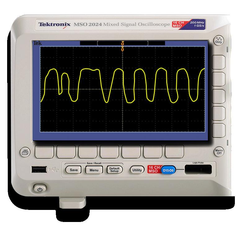
8 Getting Started 1.4 Acquisition readout Trigger status Analog baseline indicator Digital channels (MSO) Channel readout Horizontal scale readout

9 Expansion point Trigger position FilterVu indicator Vertical Trigger level Trigger readout Measurement readout Horizontal position readout
10 Vertical 2.1 Vertical What are Vertical Controls used for? You can change the vertical position of waveforms by moving them up or down on the display. To compare data, you can align a waveform above another or you can align waveforms on top of each other. You can change the vertical scale of a waveform. The waveform display will contract or expand around the ground reference level.

11 Vertical Controls 1 2
 Varies the size of the waveform on the screen.")
12 Vertical Position knob Moves the waveform up and down on the display. Before After 2 Scale (volts-per-division) Varies the size of the waveform on the screen. Before After


13 The volts/div setting is a scale factor. If the volts/div setting is 5 volts, then each vertical division represents 5 volts and an entire screen of 8 divisions can display 40 volts from top to bottom. } } } } } } } } 5 volts 5 volts 5 volts 5 volts 5 volts 5 volts 5 volts 5 volts x 8div = 40 volts from top to bottom
14 Vertical/FFT 2.3 What is Fast Fourier Transform (FFT) used for? You can use the FFT Math mode to convert a time-domain signal into its frequency components (spectrum). You can use FFT for the following kinds of analysis: analyzing harmonics, characterizing noise, testing impulse response, and analyzing vibration. The MSO/DPO2000 Series FFT is calculated from 5000 points on the display. The resulting FFT spectrum goes from DC (0 Hz) to onehalf the sample rate.

15 Frequency component Horizontal Additional information in about FFT Horizontal scale in frequency per division Frequency at the center graticule Window type: Allows you to trade off the frequency resolution and amplitude accuracy that you will see in the FFT spectrum. Vertical scale in db per division (0 db = 1VRMS)
16 Horizontal Controls 3.1 What are Horizontal Controls used for? You can adjust the Horizontal Position control to view waveform data before the trigger, after the trigger, or some of each. Horizontal When you change the horizontal position of a waveform you are changing the time between the trigger and the center of the display. This moves the waveform to the right or left on the display.
17 Horizontal Controls 1 2 3
18 Horizontal Controls Position knob Adjusts the horizontal position of all channel and math waveforms. The resolution of this control varies with the time base setting. Before Example: Post trigger acquisition After Example: Pre-trigger acquisition


19 2 Acquire button Determines how the oscilloscope processes the digitized signal before displaying it. There are two acquisition modes: Sample and Average. Sample mode: Samples are taken in evenly-spaced intervals to construct the waveform. This mode accurately represents signals most of the time. Average mode: Several waveforms are acquired and averaged point-by-point to obtain the average voltage at each time sample in the acquisition. This mode is used to reduce random noise.
20 Horizontal Controls Scale knob The scale knob (sec/div) setting varies the rate at which the waveform is drawn across the screen. Before Example: 1 sec After Example: 10 sec The sec/div setting is a scale factor. If the sec/div setting is 1 second, then each horizontal division represents 1 division and an entire screen of 10 divisions can display 10 seconds from left to right.


21 Trigger } } } } } } } } } } 1 sec 1 sec 1 sec 1 sec 1 sec 1 sec 1 sec 1 sec 1 sec 1 sec x 10 div = 10 seconds from left to right
22 Trigger Controls 4.1 What are Trigger Controls used for? Trigger controls allow you to capture single-shot waveforms and stabilize repetitive waveforms. Trigger Imagine the jumble on the screen that would result if each time the waveform was drawn across the screen, the drawing began at a different part of the signal. The trigger ensures the same part of the waveform is drawn each time, making repetitive waveforms appear stationary.
23 Trigger Controls 1 2a 3 2b

24 Trigger Controls 4.2 What does a Trigger do? When the signal matches the trigger setting, the oscilloscope captures the signal and displays it around the trigger point. Edge triggering is used most often; it captures the signal as it passes through a specified voltage level on a rising or falling edge. Untriggered display Triggered display

25 1 Trig Menu Displays the Trigger Menu 5a 5b 5c 5f 5a Type Cycles through different trigger types Edge triggers are the simplest and most commonly used trigger type, with both analog and digital signals. An edge trigger event occurs when the trigger source passes through a specified voltage level in the specified direction. Pulse width triggering, allows you to monitor a signal indefinitely and trigger on the first occurrence of a pulse with a duration (pulse width) that is outside the specified limits. Runt triggering allows you to define two levels (or thresholds). A trigger occurs when a pulse crosses one, but not both thresholds. Logic triggering allows you to trigger on any logical combination of available input channels especially useful in verifying the operation of digital logic. Setup-and Hold triggering allows you to capture setup and hold violations. Rise/Fall Time Triggering allows you to selectively trigger on fast or slow edges. Video trigger on specified fields or lines of a composite video signal. Bus trigger is used when there are various parallel or serial bus conditions.

26 Trigger Controls 4.3 5b Source Determines which signal is compared to the trigger settings. Analog channels Aux In channel AC Line Digital channels (MSO) 5d


27 5c Coupling High frequency, low frequency, and noise rejection trigger coupling are useful for eliminating noise from the trigger signal to prevent false triggering. DC Passes all components of the signal HF Reject attenuates the high frequency components of the signal LF Reject attenuates the low frequency components of the signal Noise Reject adds hysteresis to the trigger circuitry to reduce the chance of falsely triggering on noise 5d Mode Determines whether or not the oscilloscope draws a waveform based on a signal condition. In Auto mode the scope displays a signal, even without a trigger. In Normal mode the scope only displays a signal if the input signal reaches the set trigger point; otherwise the last acquired waveform remains on the display. After a trigger is detected, the scope acquires and displays one waveform.

28 Trigger Controls 4.4 2a Level When you use an Edge or Pulse trigger, the Level knob sets the amplitude level that the signal must cross to acquire a waveform. Before After 2b Set to 50% (Push to Set) The trigger level is set to the vertical midpoint between the peaks of the trigger signal. Before After
29 3 Force Trig Completes an acquisition regardless of an adequate trigger signal. This button has no effect if the acquisition is already stopped. Before After Probing
30 Probing 5.1 Probing basics Choose a probe that exceeds the signal s bandwidth by 5 times for accurate reconstruction of the signal. Probing Remember to connect the probe s ground clip to a known ground in the circuit under test. Measuring a signal requires two connections: the probe tip connection and the ground connection. Don t forget to compensate passive voltage probes to the oscilloscope.
31 Probe connections 1 2

32 Probing CH1 BNC To connect the probe, align the slot in the probe connector with key on the BNC, push to connect and twist to the right to lock the probe in place. 2 Probe comp connector Connect the probe tip to the bottom connector and the ground to the top connector labeled ground. Verify your probe is compensated correctly Check the shape of the displayed waveform. Overcompensated Undercompensated Compensated Correctly


33 Standard P2221 MSO/DPO Analog Probe Probe tip Adjustment tool Retractable hook tip BNC connector Ground lead Measurements
34 Measurements 6.1 Measurements The oscilloscope can help you to analyze your waveform through measurements. There are several ways to take measurements. You can use the graticule, the cursors, or automatic measurements. Automatic measurements use on-screen readouts to show measurement results. These readouts are updated periodically as the oscilloscope acquires new data. Measurements
35 1 Measure button
 = t Period is the time required to complete the first cycle.")
36 Measurements 6.2 The following automatic measurements are available: ( ) 1 Frequency (Hertz) = t Frequency is the reciprocal of Period. Frequency is measured over the first cycle. Period (seconds) = t Period is the time required to complete the first cycle. The first cycle is the time between the first two positive crossings, or the first two negative crossings, at the Mid Reference level. Rise Time (seconds) = t Rise Time is the time required for the first rising edge to rise from the Low Reference level to the High Reference level. Fall Time (seconds) = t Fall Time is the time required for the first falling edge to fall from the High Reference level to the Low Reference level.

 to the Period of the source (t2) waveform.")
 = t Positive Pulse Width is the time between the Mid Reference")
 = t Negative Pulse Width is the time between the Mid Reference")
37 Delay (seconds) = t Delay is the time between the first occurrences of the specified Mid Reference crossings of two waveforms. ( ) t1 Phase ( ) = t2 x 360 Phase is the ratio of the Delay between the first Mid Reference crossings of two waveforms (t1) to the Period of the source (t2) waveform. Phase is expressed in degrees. 360 degrees comprise one cycle. Positive Pulse Width (seconds) = t Positive Pulse Width is the time between the Mid Reference crossings of the first positive pulse. Negative Pulse Width (seconds) = t Negative Pulse Width is the time between the Mid Reference crossings of the first negative pulse. ( ) t1 Positive Duty Cycle (%) = t2 x 100% Positive Duty Cycle is the ratio of the Positive Pulse Width (t1) to the Period (t2). Positive Duty Cycle is measured over the first cycle.
 t1 Negative Duty Cycle (%) = t2 x 100% Negative Duty Cycle is the ratio of the")


38 Measurements 6.3 ( ) t1 Negative Duty Cycle (%) = t2 x 100% Negative Duty Cycle is the ratio of the Negative Pulse Width (t1) to the Period (t2). Negative Duty Cycle is measured over the first cycle. Burst Width (seconds) = t Burst Width is the time from the first Mid Reference crossing to the last Mid Reference crossing. Peak-to-peak (Volts) = a Peak-to-peak is the difference between the Max value and the Min value. Amplitude (Volts) = a Amplitude is the difference between the High value and the Low value. Max (Volts) Max is the maximum value.


39 Min (Volts) Min is the minimum value. High (Volts) If the High-Low Method is Histogram, High is the highest density of points above the midpoint of the waveform. If the High-Low Method is Min-Max, High is equal to Max. Low (Volts) If the High-Low Method is Histogram, Low is the highest density of points below the midpoint of the waveform. If the High-Low Method is Min-Max, Low is equal to Min. a1 Positive Overshoot (%) = ( a2) x 100% Positive Overshoot is the difference between Max and High (a1), divided by Amplitude (a2). a1 Negative Overshoot (%) = ( a2) x 100% Negative Overshoot is the difference between Min and Low (a1), divided by Amplitude (a2).
 RMS (Volts) = n RMS is the true Root Mean Square value over the entire record.")

40 Measurements 6.4 ( S0 + S Sn ) Mean (Volts) = n Mean is the arithmetic mean value over the entire record. ( S0 + S Sn ) Cycle Mean (Volts) = n Cycle Mean is the arithmetic mean value. Cycle Mean is calculated over the first cycle. ( S0 2 + S Sn 2 ) RMS (Volts) = n RMS is the true Root Mean Square value over the entire record. ( S0 2 + S Sn 2 ) Cycle RMS (Volts) = n Cycle RMS is the true Root Mean Square value. Cycle RMS is calculated over the first cycle. Positive Pulse Count = n Positive Pulse Count is the number of positive pulses that rise above the Mid Reference level.

 = ( S0 + S1 +... + Sn ) x (sample interval) Area is the area under the curve, calculated by integrating the samples.")
 x (sample interval) Cycle Area is the area under the curve, calculated by integrating the samples in the first cycle.")
41 Negative Pulse Count = n Negative Pulse Count is the number of negative pulses that fall below the Mid Reference level. Rising Edge Count = n Rising Edge Count is the number of positive transitions from the Low Reference value to the High Reference value. Falling Edge Count = n Falling Edge Count is the number of negative transitions from the High Reference value to the Low Reference value. Area (Volt-seconds) = ( S0 + S Sn ) x (sample interval) Area is the area under the curve, calculated by integrating the samples. The area measured above ground is positive. The area measured below ground is negative. Cycle Area (Volt-seconds) = ( S0 + S Sn ) x (sample interval) Cycle Area is the area under the curve, calculated by integrating the samples in the first cycle. The area measured above ground is positive. The area measured below ground is negative.
42 For the most current information visit our website at tektronix.com/oscilloscopes Copyright Tektronix
Introduction to Oscilloscopes Instructor s Guide
 Introduction to Oscilloscopes A collection of lab exercises to introduce you to the basic controls of a digital oscilloscope in order to make common electronic measurements. Revision 1.0 Page 1 of 25 Copyright
Faculty of Engineering, Thammasat University
 Faculty of Engineering, Thammasat University Experiment 6: Oscilloscope (For room 506) Objectives: 1. To familiarize you with the Oscilloscope and Function Generator User Manual: Oscilloscope 1 5 9 4 7
Digital Debug With Oscilloscopes Lab Experiment
 Digital Debug With Oscilloscopes A collection of lab exercises to introduce you to digital debugging techniques with a digital oscilloscope. Revision 1.0 Page 1 of 23 Revision 1.0 Page 2 of 23 Copyright
MSO-5000B Mixed Storage Oscilloscope User Manual
 MSO-5000B Mixed Storage Oscilloscope User Manual Contents Contents CONTENTS... I COPYRIGHT DECLARATION... IV CHAPTER 1 SAFETY TIPS... 1 1.1 GENERAL SAFETY SUMMARY... 1 1.2 SAFETY TERMS AND SYMBOLS... 2
DSO5000P Series Digital Storage Oscilloscope User Manual. (Version 1.1)
") DSO5000P Series Digital Storage Oscilloscope User Manual (Version 1.1) Contents Contents Contents... i Chapter 1 Safety Tips... 1 1.1 General Safety Summary... 1 1.2 Safety Terms and Symbols... 2 1.3 Terms
DSO5000P Series Digital Storage Oscilloscope User Manual (Version 1.1) Contents Contents Contents... i Chapter 1 Safety Tips... 1 1.1 General Safety Summary... 1 1.2 Safety Terms and Symbols... 2 1.3 Terms
DST Series B Type Digital Storage Oscilloscope User Manual
 DST Series B Type Digital Storage Oscilloscope User Manual Contents Contents Contents... i Copyright Declaration... iv Chapter 1 Safety Tips... 1 1.1 General Safety Summary... 1 1.2 Safety Terms and Symbols...
DSO1000E/F Series Digital Storage Oscilloscope User Manual. (Version 1.3)
") DSO1000E/F Series Digital Storage Oscilloscope User Manual (Version 1.3) Copyright Declaration All rights reserved; no part of this document may be reproduced or transmitted in any form or by any means,
DSO1000E/F Series Digital Storage Oscilloscope User Manual (Version 1.3) Copyright Declaration All rights reserved; no part of this document may be reproduced or transmitted in any form or by any means,
Specifications for DS1000CA Series
 Revised December, 2009 RIGOL Specifications for DS1000CA Series All specifications apply to the DS1000CA Series Oscilloscopes unless noted otherwise. To meet these specifications, two conditions must first
User Manual Series. Digital Storage Oscilloscope 6810, 6806, March Copyright Protek Test & Measurement 2005 All Rights Reserved
 User Manual March 2005 6800 Series Digital Storage Oscilloscope 6810, 6806, 6804 Copyright Protek Test & Measurement 2005 All Rights Reserved Copyright Protek Test & Measurement 2005 All Rights Reserved.
DSO4000BC Series Digital Storage Oscilloscope User Manual
 DSO4000BC Series Digital Storage Oscilloscope User Manual (V1.3) Copyright Declaration All rights reserved; no part of this document may be reproduced or transmitted in any form or by any means, electronic
Chapter 5 : Specifications
 Chapter 5 : Specifications All specifications apply to the DS1000B Series Oscilloscopes and a probe with the Attenuation switch set to 10X unless noted otherwise. To meet these specifications, two conditions
Appendix A: Specifications
 All specifications apply to the TDS 200-Series Digital Oscilloscopes and a P2100 probe with the Attenuation switch set to 10X unless noted otherwise. To meet specifications, two conditions must first be
Reference. TDS6000 Series Digital Storage Oscilloscopes
 Reference TDS6000 Series Digital Storage Oscilloscopes 07-703-0 077030 To Use the Front Panel You can use the dedicated, front-panel knobs and buttons to do the most commonly performed operations. Turn
DSO4000 Series Digital Storage Oscilloscope User Manual. (Version 1.3)
") DSO4000 Series Digital Storage Oscilloscope User Manual (Version 1.3) Contents Contents... i Safety Tips... 1 General Safety Summary... 1 Safety Terms and Symbols... 2 Product Scrapping... 2 Brief Introduction
DSO4000 Series Digital Storage Oscilloscope User Manual (Version 1.3) Contents Contents... i Safety Tips... 1 General Safety Summary... 1 Safety Terms and Symbols... 2 Product Scrapping... 2 Brief Introduction
RIGOL Data Sheet. DS1000E, DS1000D Series Digital Oscilloscopes DS1102E, DS1052E, DS1102D, DS1052D. Product Overview. Easy to Use Design.
 RIGOL Data Sheet DS1000E, DS1000D Series Digital Oscilloscopes DS1102E, DS1052E, DS1102D, DS1052D Product Overview The DS1000E, DS1000D series instruments are economical, high-performance digital oscilloscopes.
Measurement Bench. Accessories. Power supply. Wave form generator. Multimetre. Oscilloscope. Dr. L.Scucchia
 Measurement Bench Accessories Power supply Wave form generator Multimetre Oscilloscope OSCILLOSCOPE Oscilloscope (1) The oscilloscope allows to display a voltage (vertical axis - Y axis) versus time (horizontal
N acquisitions, all channels simultaneously, N is selectable from 4, 16, 64, and 128 Inputs
 With compliments All specifications apply to the TDS 200-Series Digital Real-Time Oscilloscope with a P2100 probe with the Attenuation switch set to 10X unless noted otherwise. To meet specifications,
Oscilloscope Fundamentals. For Electrical Engineering and Physics Undergraduate Students
 Oscilloscope Fundamentals For Electrical Engineering and Physics Undergraduate Students Agenda What is an oscilloscope? Probing basics (low-frequency model) Making voltage and timing measurements Properly
UNIVERSITY OF CALIFORNIA, SANTA BARBARA Department of Electrical and Computer Engineering. ECE 2A & 2B Laboratory Equipment Information
 UNIVERSITY OF CALIFORNIA, SANTA BARBARA Department of Electrical and Computer Engineering ECE 2A & 2B Laboratory Equipment Information Table of Contents Digital Multi-Meter (DMM)... 1 Features... 1 Using
DS1000B Series Digital Oscilloscopes
 Product Overview DS1000B series oscilloscopes are designed with four analog channels and 1 external trigger channel, which can capture multi-channel signal simultaneously and meet industrial needs. The
EENG-201 Experiment # 4: Function Generator, Oscilloscope
 EENG-201 Experiment # 4: Function Generator, Oscilloscope I. Objectives Upon completion of this experiment, the student should be able to 1. To become familiar with the use of a function generator. 2.
ECE65 Introduction to the Function Generator and the Oscilloscope Created by: Eldridge Alcantara (Spring 2007)
") ECE65 Introduction to the Function Generator and the Oscilloscope Created by: Eldridge Alcantara (Spring 2007) I. Getting Started with the Function Generator OUTPUT Red Clip Small Black Clip 1) Turn on
ECE65 Introduction to the Function Generator and the Oscilloscope Created by: Eldridge Alcantara (Spring 2007) I. Getting Started with the Function Generator OUTPUT Red Clip Small Black Clip 1) Turn on
TDS1000B and TDS2000B Series Oscilloscopes Operator Training Kit Manual
 TDS1000B and TDS2000B Series Oscilloscopes Operator Training Kit Manual 071-2199-00 www.tektronix.com Copyright Tektronix. All rights reserved. Licensed software products are owned by Tektronix or its
The oscilloscope is an essential tool if you plan to design or repair electronic equipment. It lets you "see" electrical signals.
 XYZs/intro.html Introduction The oscilloscope is an essential tool if you plan to design or repair electronic equipment. It lets you "see" electrical signals. Energy, vibrating particles, and other invisible
Advanced Lab LAB 6: Signal Acquisition & Spectrum Analysis Using VirtualBench DSA Equipment: Objectives:
 Advanced Lab LAB 6: Signal Acquisition & Spectrum Analysis Using VirtualBench DSA Equipment: Pentium PC with National Instruments PCI-MIO-16E-4 data-acquisition board (12-bit resolution; software-controlled
54645D. Mixed Signal Oscilloscope
 54645D Mixed Signal Oscilloscope Page 1 of 42 Instructions for the use of the 54645D Mixed Signal Oscilloscope This pamphlet is intended to give you (the student) an overview on the use of the 54645D Mixed
Department of Electrical & Computer Engineering OSCILLOSCOPE GUIDE. Tektronix TDS2000 Series
 OSCILLOSCOPE Department of Electrical & Computer Engineering GUIDE Tektronix TDS2000 Series Contents 1 INTRODUCTION... 2 2 OSCILLOSCOPE OVERVIEW... 2 3 INSTRUMENT FRONT PANEL... 3 Power Switch... 3 USB
DSO8000E SERIES HANDHELD OSCILLOSCOPE
 DSO8000E SERIES HANDHELD OSCILLOSCOPE USER S MANUAL 8072E/8102E/8152E/8202E (V1.0.1) Contents Contents Contents... i Copyright Declaration... iii Chapter 1 Safety Tips... 1 1.1 General Safety Summary...
LAB #7: Digital Signal Processing
 LAB #7: Digital Signal Processing Equipment: Pentium PC with NI PCI-MIO-16E-4 data-acquisition board NI BNC 2120 Accessory Box VirtualBench Instrument Library version 2.6 Function Generator (Tektronix
Experiment #2: Introduction to Lab Equipment: Function Generator, Oscilloscope, and Multisim
 SCHOOL OF ENGINEERING AND APPLIED SCIENCE DEPARTMENT OF ELECTRICAL AND COMPUTER ENGINEERING ECE 2110: CIRCUIT THEORY LABORATORY Experiment #2: Introduction to Lab Equipment: Function Generator, Oscilloscope,
XYZs of Oscilloscopes. Primer
 XYZs of Oscilloscopes Primer Primer Table of Contents Introduction................................. 4 Signal Integrity............................ 5-6 The Significance of Signal Integrity................
PHYSICS 171 UNIVERSITY PHYSICS LAB II. Experiment 4. Alternating Current Measurement
 PHYSICS 171 UNIVERSITY PHYSICS LAB II Experiment 4 Alternating Current Measurement Equipment: Supplies: Oscilloscope, Function Generator. Filament Transformer. A sine wave A.C. signal has three basic properties:
Department of Electrical and Computer Engineering. Laboratory Experiment 1. Function Generator and Oscilloscope
 Department of Electrical and Computer Engineering Laboratory Experiment 1 Function Generator and Oscilloscope The purpose of this first laboratory assignment is to acquaint you with the function generator
B. Equipment. Advanced Lab
 Advanced Lab Measuring Periodic Signals Using a Digital Oscilloscope A. Introduction and Background We will use a digital oscilloscope to characterize several different periodic voltage signals. We will
DS1102E, DS1052E, DS1102D, DS1052D
 RIGOL Data Sheet DS1000E, DS1000D Series Digital Oscilloscopes DS1102E, DS1052E, DS1102D, DS1052D Product Overview DS1000E, DS1000D series are kinds of economical digital oscilloscope with high-performance.
USER S MANUAL 1062S/1122S/1152S/1202S
 DSO1000S SERIES HANDHELD OSCILLOSCOPE USER S MANUAL 1062S/1122S/1152S/1202S (V 1.0.1) Contents Contents Contents... i Copyright Declaration... iii Chapter 1 Safety Tips... 1 1.1 General Safety Summary...
EXPERIMENT NUMBER 2 BASIC OSCILLOSCOPE OPERATIONS
 1 EXPERIMENT NUMBER 2 BASIC OSCILLOSCOPE OPERATIONS The oscilloscope is the most versatile and most important tool in this lab and is probably the best tool an electrical engineer uses. This outline guides
TDS1000 & TDS2000 Series Oscilloscopes Operator Training Kit Manual
 TDS1000 & TDS2000 Series Oscilloscopes Operator Training Kit Manual 071-1151-00 www.tektronix.com This product training document file is protected by Copyright Tektronix, Inc. All rights reserved. End
RIGOL Data Sheet. DS1000E, DS1000D Series Digital Oscilloscopes DS1102E, DS1052E, DS1102D, DS1052D. Product Overview. Applications. Easy to Use Design
 RIGOL Data Sheet DS1000E, DS1000D Series Digital Oscilloscopes DS1102E, DS1052E, DS1102D, DS1052D Product Overview DS1000E, DS1000D series are kinds of economical digital oscilloscope with high-performance.
XYZs of Oscilloscopes PRIMER
 XYZs of Oscilloscopes PRIMER Primer Table of Contents Introduction...4 Signal Integrity...5-6 The Significance of Signal Integrity...5 Why is Signal Integrity a Problem?...5 Viewing the Analog Origins
Data Sheet. Digital Storage Oscilloscope. Features & Benefits. Applications. Ease-of-Use Feature DSO5202BMT DSO5102BMT DSO5062BMT
 Data Sheet Digital Storage Oscilloscope DSO5202BMT DSO5102BMT DSO5062BMT Features & Benefits 200/100/60MHz Bandwidths 1GSa/s Real Time Sample Rate 2M Memory Depth Trigger mode: Edge, Pulse Width, Video,
AE Agricultural Customer Services Play-by-Play Tekscope Manual
 1 2012 AE Agricultural Customer Services Play-by-Play Tekscope Manual TABLE OF CONTENTS I. Definitions II. Waveform Properties 1 III. Scientific Notation... 2 IV. Transient Levels of Concern a. ASAE Paper
P a g e 1 ST985. TDR Cable Analyzer Instruction Manual. Analog Arts Inc.
 P a g e 1 ST985 TDR Cable Analyzer Instruction Manual Analog Arts Inc. www.analogarts.com P a g e 2 Contents Software Installation... 4 Specifications... 4 Handling Precautions... 4 Operation Instruction...
How to Setup and Use an Oscilloscope
 How to Setup and Use an Oscilloscope An oscilloscope is a device that is used to measure voltage with respect to time. Oscilloscopes are essential pieces of test equipment used in the development and testing
LAB I. INTRODUCTION TO LAB EQUIPMENT
 1. OBJECTIVE LAB I. INTRODUCTION TO LAB EQUIPMENT In this lab you will learn how to properly operate the oscilloscope Agilent MSO6032A, the Keithley Source Measure Unit (SMU) 2430, the function generator
Digital Fundamentals 8/25/2016. Summary. Summary. Floyd. Chapter 1. Analog Quantities
 8/25/206 Digital Fundamentals Tenth Edition Floyd Chapter Analog Quantities Most natural quantities that we see are analog and vary continuously. Analog systems can generally handle higher power than digital
LAB 7: THE OSCILLOSCOPE
 LAB 7: THE OSCILLOSCOPE Equipment List: Dual Trace Oscilloscope HP function generator HP-DMM 2 BNC-to-BNC 1 cables (one long, one short) 1 BNC-to-banana 1 BNC-probe Hand-held DMM (freq mode) Purpose: To
Artisan Technology Group is your source for quality new and certified-used/pre-owned equipment
 Artisan Technology Group is your source for quality new and certified-used/pre-owned equipment FAST SHIPPING AND DELIVERY TENS OF THOUSANDS OF IN-STOCK ITEMS EQUIPMENT DEMOS HUNDREDS OF MANUFACTURERS SUPPORTED
Introduction to Lab Instruments
 ECE316, Experiment 00, 2017 Communications Lab, University of Toronto Introduction to Lab Instruments Bruno Korst - bkf@comm.utoronto.ca Abstract This experiment will review the use of three lab instruments
ENGR 210 Lab 6 Use of the Function Generator & Oscilloscope
 ENGR 210 Lab 6 Use of the Function Generator & Oscilloscope In this laboratory you will learn to use two additional instruments in the laboratory, namely the function/arbitrary waveform generator, which
DPO3PWR, MDO3PWR and DPO4PWR Power Analysis Modules ZZZ User Manual
 x DPO3PWR, MDO3PWR and DPO4PWR Power Analysis Modules ZZZ User Manual *P071263101* 071-2631-01 xx DPO3PWR, MDO3PWR and DPO4PWR Power Analysis Modules ZZZ User Manual www.tektronix.com 071-2631-01 Copyright
Combinational logic: Breadboard adders
 ! ENEE 245: Digital Circuits & Systems Lab Lab 1 Combinational logic: Breadboard adders ENEE 245: Digital Circuits and Systems Laboratory Lab 1 Objectives The objectives of this laboratory are the following:
Getting the most out of your Measurements Workshop. Mike Schnecker
 Getting the most out of your Measurements Workshop Mike Schnecker Agenda Oscilloscope Basics Using a RTE1000 Series Oscilloscope. Probing Basics Passive probe compensation Ground lead effects Vertical
DSO 3000 Series Oscilloscope
 Key Features 200 / 100 / 70MHz bandwidths Arbitrary/Function Waveform Generator + Synchronizing Signal + External Trigger 1GSa/s Real Time sample rate 7 large color display, WVGA (800x480) 2 Channels,
Testing Sensors & Actors Using Digital Oscilloscopes
 Testing Sensors & Actors Using Digital Oscilloscopes APPLICATION BRIEF February 14, 2012 Dr. Michael Lauterbach & Arthur Pini Summary Sensors and actors are used in a wide variety of electronic products
2 Oscilloscope Familiarization
 Lab 2 Oscilloscope Familiarization What You Need To Know: Voltages and currents in an electronic circuit as in a CD player, mobile phone or TV set vary in time. Throughout the course you will investigate
DSOXEDK Educator s Oscilloscope Training Kit. Lab Guide and Tutorial for Agilent 4000 X-Series Oscilloscopes
 DSOXEDK Educator s Oscilloscope Training Kit Lab Guide and Tutorial for Agilent 4000 X-Series Oscilloscopes s1 Notices Agilent Technologies, Inc. 2008-2012 The copyright on this instructional material
Sampling and Reconstruction
 Experiment 10 Sampling and Reconstruction In this experiment we shall learn how an analog signal can be sampled in the time domain and then how the same samples can be used to reconstruct the original
How to Setup a Real-time Oscilloscope to Measure Jitter
 TECHNICAL NOTE How to Setup a Real-time Oscilloscope to Measure Jitter by Gary Giust, PhD NOTE-3, Version 1 (February 16, 2016) Table of Contents Table of Contents... 1 Introduction... 2 Step 1 - Initialize
Tektronix MDO3000 Series Oscilloscope. Demonstration Guide
 Tektronix MDO3000 Series Oscilloscope 2 www.tektronix.com/mdo3000 Table of Contents Tektronix MDO3000 Series Oscilloscope... 4 About This Guide... 6 Powering on the Board... 8 MDO3000 Series Front Panel
WELCOME TO PHYC 307L Junior Lab II
 WELCOME TO PHYC 307L Junior Lab II Spring Semester 2019 Instructor: Dr Michael Hasselbeck Challenging Modern Physics experiments Require independent problem solving harder than intro physics labs 10 experiments
UCE-DSO210 DIGITAL OSCILLOSCOPE USER MANUAL. FATIH GENÇ UCORE ELECTRONICS REV1
 UCE-DSO210 DIGITAL OSCILLOSCOPE USER MANUAL FATIH GENÇ UCORE ELECTRONICS www.ucore-electronics.com 2017 - REV1 Contents 1. Introduction... 2 2. Turn on or turn off... 3 3. Oscilloscope Mode... 3 3.1. Display
What the LSA1000 Does and How
 2 About the LSA1000 What the LSA1000 Does and How The LSA1000 is an ideal instrument for capturing, digitizing and analyzing high-speed electronic signals. Moreover, it has been optimized for system-integration
Signal Processing for Digitizers
 Signal Processing for Digitizers Modular digitizers allow accurate, high resolution data acquisition that can be quickly transferred to a host computer. Signal processing functions, applied in the digitizer
Sonoma State University Department of Engineering Science Spring 2017
 EE 110 Introduction to Engineering & Laboratory Experience Saeid Rahimi, Ph.D. Lab 4 Introduction to AC Measurements (I) AC signals, Function Generators and Oscilloscopes Function Generator (AC) Battery
DS1052E, DS1102D, DS1052D
 RIGOL Data Sheet Product Overview DS1000E, DS1000D series are kinds of economical digital oscilloscope with high-performance. DS1000E series are designed with dual channels and 1 external trigger channel.
Digital Fundamentals
 Digital Fundamentals Tenth Edition Floyd Chapter 1 2009 Pearson Education, Upper 2008 Pearson Saddle River, Education NJ 07458. All Rights Reserved Objectives After completing this unit, you should be
UTD4000 Four-channel User Manual. Safety Instructions
 Safety Instructions This unit is designed and manufactured strictly in accordance with GB4793 safety requirements for electronic testing meters and IEC61010-1 safety standards. It fully meets CAT II 600V
Help Volume Agilent Technologies. All rights reserved. Instrument: Agilent Technologies 16533/34A Digitizing Oscilloscope
 Help Volume 1992-2002 Agilent Technologies. All rights reserved. Instrument: Agilent Technologies 16533/34A Digitizing Oscilloscope Agilent Technologies 16533/34A Digitizing Oscilloscope The Agilent Technologies
Exercise 4 - THE OSCILLOSCOPE
 Exercise 4 - THE OSCILLOSCOPE INTRODUCTION You have been exposed to analogue oscilloscopes in the first year lab. As you are probably aware, the complexity of the instruments, along with their importance
The Oscilloscope. Vision is the art of seeing things invisible. J. Swift ( ) OBJECTIVE To learn to operate a digital oscilloscope.
 OBJECTIVE To learn to operate a digital oscilloscope.") The Oscilloscope Vision is the art of seeing things invisible. J. Swift (1667-1745) OBJECTIVE To learn to operate a digital oscilloscope. THEORY The oscilloscope, or scope for short, is a device for drawing
The Oscilloscope Vision is the art of seeing things invisible. J. Swift (1667-1745) OBJECTIVE To learn to operate a digital oscilloscope. THEORY The oscilloscope, or scope for short, is a device for drawing
LABORATORY 4. Palomar College ENGR210 Spring 2017 ASSIGNED: 3/21/17
 LABORATORY 4 ASSIGNED: 3/21/17 OBJECTIVE: The purpose of this lab is to evaluate the transient and steady-state circuit response of first order and second order circuits. MINIMUM EQUIPMENT LIST: You will
Fourier Theory & Practice, Part II: Practice Operating the Agilent Series Scope with Measurement/Storage Module
 Fourier Theory & Practice, Part II: Practice Operating the Agilent 54600 Series Scope with Measurement/Storage Module By: Robert Witte Agilent Technologies Introduction: This product note provides a brief
Laboratory Equipment Instruction Manual 2011
 University of Toronto Department of Electrical and Computer Engineering Instrumentation Laboratory GB341 Laboratory Equipment Instruction Manual 2011 Page 1. Wires and Cables A-2 2. Protoboard A-3 3. DC
ECE 480: SENIOR DESIGN LABORATORY
 ECE 480: SENIOR DESIGN LABORATORY DEPARTMENT OF ELECTRICAL AND COMPUTER ENGINEERING MICHIGAN STATE UNIVERSITY I. TITLE: Lab I - Introduction to the Oscilloscope, Function Generator, Digital Multimeter
OL-612 PORTABLE MIXED SIGNAL DIGITAL STORAGE OSCILLOSCOPE
 OL-612 PORTABLE MIXED SIGNAL DIGITAL STORAGE OSCILLOSCOPE Version Date Software Version 1.0 October 2014 4.2-0 MI2012-99 Washington Street Melrose, MA 02176 Phone 781-665-1400 Toll Free 1-800-517-8431
User s Guide RIGOL. DS1000E, DS1000D Series Digital Oscilloscopes DS1102E, DS1052E, DS1102D, DS1052D. Publication number UGA July 2009
 User s Guide RIGOL Publication number UGA07111-1110 July 2009 DS1000E, DS1000D Series Digital Oscilloscopes DS1102E, DS1052E, DS1102D, DS1052D All Rights Reserved 1. All Rights Reserved 2. RIGOL products
Dr. Cahit Karakuş ANALOG SİNYALLER
 Dr. Cahit Karakuş ANALOG SİNYALLER Sinusoidal Waveform Mathematically it is represented as: Sinusoidal Waveform Unit of measurement for horizontal axis can be time, degrees or radians. Sinusoidal Waveform
PeakTech 1210/1215. Bedienungsanleitung / operation manual. Digital Oszilloskop mit Farbdisplay Digital Oscilloscope / with colour display
 PeakTech 1210/1215 Bedienungsanleitung / operation manual Digital Oszilloskop mit Farbdisplay Digital Oscilloscope / with colour display 1. Safety Precautions This product complies with the requirements
Name EET 1131 Lab #2 Oscilloscope and Multisim
 Name EET 1131 Lab #2 Oscilloscope and Multisim Section 1. Oscilloscope Introduction Equipment and Components Safety glasses Logic probe ETS-7000 Digital-Analog Training System Fluke 45 Digital Multimeter
Oscilloscope Operation. Visualizing Signals and Making Measurements
 Oscilloscope Operation Visualizing Signals and Making Measurements Set Up Oscilloscope Start with the oscilloscope off, with the input plugged into channel one. Press the power button to turn the scope
Cornerstone Electronics Technology and Robotics Week 21 Electricity & Electronics Section 10.5, Oscilloscope
 Cornerstone Electronics Technology and Robotics Week 21 Electricity & Electronics Section 10.5, Oscilloscope Field trip to Deerhaven Generation Plant: Administration: o Prayer o Turn in quiz Electricity
Elizabethtown College Department of Physics and Engineering PHY104. Lab # 9- Oscilloscope and RC Circuit
 Elizabethtown College Department of Physics and Engineering PHY104 Lab # 9- Oscilloscope and RC Circuit Introduction This lab introduces you to very important tools, the oscilloscope and the waveform generator.
EE 3302 LAB 1 EQIUPMENT ORIENTATION
 EE 3302 LAB 1 EQIUPMENT ORIENTATION Pre Lab: Calculate the theoretical gain of the 4 th order Butterworth filter (using the formula provided. Record your answers in Table 1 before you come to class. Introduction:
Announcement. Copyright. Trademark Logo. Declaration
 Announcement The content in this manual could be changed without prior notice. NANJING GLARUN-ATTEN TECHNOLOGY CO. LTD provides no warranty of any kind to this manual and assumes no liability or responsibility
Multiple Instrument Station Module
 Multiple Instrument Station Module Digital Storage Oscilloscope Vertical Channels Sampling rate Bandwidth Coupling Input impedance Vertical sensitivity Vertical resolution Max. input voltage Horizontal
Laboratory 1 Generating and viewing signals rev. 20e. Oscilloscope Settings
 1 2 Laboratory 1 Generating and viewing signals rev. 20e Purpose: Familiarization with the basic functions of an oscilloscope and of a signal generator. Adjusting and measuring specific parameters of signals.
Sirindhorn International Institute of Technology Thammasat University at Rangsit
 Sirindhorn International Institute of Technology Thammasat University at Rangsit School of Information, Computer and Communication Technology COURSE : ECS 210 Basic Electrical Engineering Lab INSTRUCTOR
DSOXEDK Educator s Oscilloscope Training Kit
 DSOXEDK Educator s Oscilloscope Training Kit Lab Guide and Tutorial for Keysight 4000 X-Series Oscilloscopes Notices Keysight Technologies, Inc. 2008-2012 No part of this manual may be reproduced in any
ENGR 1110: Introduction to Engineering Lab 7 Pulse Width Modulation (PWM)
") ENGR 1110: Introduction to Engineering Lab 7 Pulse Width Modulation (PWM) Supplies Needed Motor control board, Transmitter (with good batteries), Receiver Equipment Used Oscilloscope, Function Generator,
ENGR 1110: Introduction to Engineering Lab 7 Pulse Width Modulation (PWM) Supplies Needed Motor control board, Transmitter (with good batteries), Receiver Equipment Used Oscilloscope, Function Generator,
Tektronix digital oscilloscope, BK Precision Function Generator, coaxial cables, breadboard, the crystal earpiece from your AM radio kit.
 Experiment 0: Review I. References The 174 and 275 Lab Manuals Any standard text on error analysis (for example, Introduction to Error Analysis, J. Taylor, University Science Books, 1997) The manual for
Lab 6 Instrument Familiarization
 Lab 6 Instrument Familiarization What You Need To Know: Voltages and currents in an electronic circuit as in a CD player, mobile phone or TV set vary in time. Throughout todays lab you will investigate
Cleverscope Model CS320A - CS328A Data Sheet
 Cleverscope Model CS320A - CS328A Data Sheet Summary Cleverscope Model CS320A or CS328A is a USB or Ethernet connected, PC hosted oscilloscope and spectrum analyser. It s easy to use Windows program integrates
PeakTech 1190/1230. Operation manual. Digital Oscilloscope / with 16-CH logic analyzer
 PeakTech 1190/1230 Operation manual Digital Oscilloscope / with 16-CH logic analyzer 1. Safety Precautions This product complies with the requirements of the following European Community Directives: 2004/108/EC
University of California, San Diego Department of Electrical and Computer Engineering
 University of California, San Diego Department of Electrical and Computer Engineering Part One: Introduction of Lab TAs ECE65, Spring 2007 Lab 0, ECE 65 Lab Orientation 1) James Liao, geniojames@yahoo.com
HDSO1000 Series Handheld Oscilloscope User Manual
 HDSO1000 Series Handheld Oscilloscope User Manual Saluki Technology Inc. The document applies to the handheld oscilloscopes of the following models: HDSO1072 Handheld Oscilloscope HDSO1102 Handheld Oscilloscope
OD-610 OD-620 DIGITAL OSCILLOSCOPE
 OD-610 OD-620 DIGITAL OSCILLOSCOPE Version Date Software Version 1.1 September 2014 2.1.0.3-0 MI2010-99 Washington Street Melrose, MA 02176 Phone 781-665-1400 Toll Free 1-800-517-8431 Visit us at www.testequipmentdepot.com
Introduction to Basic Laboratory Instruments
 Introduction to Contents: 1. Objectives... 2 2. Laboratory Safety... 2 3.... 2 4. Using a DC Power Supply... 2 5. Using a Function Generator... 3 5.1 Turn on the Instrument... 3 5.2 Setting Signal Type...
LeCroy 9304A, 9304AM Digital Oscilloscopes 200 MHz Bandwidth, 100 MS/s. Main Features
 LeCroy 9304A, 9304AM Digital Oscilloscopes 200 MHz Bandwidth, 100 MS/s Main Features Four Channels 50k and 200k Point Records DOS Compatible Floppy Disk, PCMCIA portable hard drive and Memory Card Options
U1571A Ni-MH Battery Pack for U1600A Handheld Oscilloscopes
 United States Home >... > Oscilloscope Accessories > U1600 Series Oscilloscope Accessories > U1571A Ni-MH Battery Pack for U1600A Handheld Oscilloscopes Key Specifications Features Ni-MH Battery Pack,