EMC Pulse Measurements
|
|
|
- Augustine Sparks
- 6 years ago
- Views:
Transcription


1 EMC Pulse Measurements and Custom Thresholding Presented to the Long Island/NY IEEE Electromagnetic Compatibility and Instrumentation & Measurement Societies - May 13, 2008 Surge ESD EFT
2 Contents EMC measurement requirements How thresholds affect pulse measurement definitions and why standard pulse parameters will not work for EMC pulses Measurement thresholds for ESD pulses Sequenced acquisition for EFT (Electrical Fast Transient) pulses Parameter limiters applied to filter EMC pulse statistics Custom measurements
3 EMC Measurement Requirements
4 4 Quadrants of EMC/ESD Testing Radiated Emissions Will the EUT create emissions that interfere with the operation of other products? Radiated Immunity Will the EUT be susceptible to emissions from other devices, either through the air or via cables? EUT = Equipment Under Test Conducted Emissions How much noise voltage is injected back into the mains by the EUT? Conducted Immunity Will the EUT be susceptible to transients generated by switching of capacitive or inductive components? Oscilloscopes used for Radiated Immunity Conducted Immunity "Pulsed EMI tests: ESD (Electrostatic Discharge) EFT (Electrical Fast Transient) Surge

, etc.")
5 Test Requirements Generate a Burst, Surge, or ESD pulse (for example, with an ESD gun) Verify the pulse shape(s) from the generator with an oscilloscope before each test Rise Time Fall Time Width Ensure that the DUT still operates correctly during test, for example: Automotive engine control unit still transmits proper messages Telecom board serial data messages are uncorrupted Consumer electronics item still functions ESD Standards: IEC , EN , ITU, UL, FCC, Telcordia, ANSI, Bellcore, Proprietary (Military, Automotive), etc. The majority of Immunity Testing follows the IEC (CE Mark)
6 ESD Testing Electrostatic Discharge Measurement Steps Pulse Characteristics T rise = 0.7 to 1.0 ns T fall = 0.7 to 1.0 ns Measurement Needs Capture a Single Pulse Measure one pulse, verify rise time for positive pulses, verify fall time for negative pulses 1 GHz, 2 GHz, or 3 GHz+ scope depending on standard specification How is risetime defined on this ESD pulse? 10%-90% risetime is only meaningful if 0% and 100% levels exist and have been defined on the pulse.
7 Pulse Measurement Definitions
8 IEEE Standard Pulse Definitions How Oscilloscopes Measure Pulse Parameters Oscilloscopes determine pulse parameters from Top and Base values
9 IEEE Pulse Definitions How Pulse Measurements Are Determined Pulse measurement definitions are defined by the IEEE Std "IEEE standard on transitions, pulses, and related waveforms" Oscilloscopes conform to the IEEE pulse measurement definitions, and Top and Base are determined statistically based on the two modes of a voltage level histogram. Top and Base form the 100% and 0% reference levels which are used for measurements such as amplitude, risetime, falltime, period, frequency, width, duty cycle, overshoot, and virtually every timing measurement. Top and Base must first be calculated correctly in order for timing and amplitude measurements to produce the correct measurement result.
10 Clock Top and Base correctly determined from voltage histogram Top Clock pulses with clearly delineated Top and Base Two main modes emerge from the voltage level histogram, identifying the steady state values of Top and Base Base


11 ESD Top and Base are not meaningful for pulse measurements What happens when standard pulse parameters are applied to an ESD waveform? A voltage level histogram of this ESD pulse does not result in the identification of two main modes. Standard pulse parameters will not be meaningful in this case. Top ESD pulse Base

12 ESD Top and Base are not meaningful for pulse measurements With Top (100%) and Base (0%) identified in the following locations, the 10%-90% risetime measurement will only encompass a very small portion of the total ESD pulse rising edge Top Base
 use 0% and Max, instead of Top and Base to calculate 10%-90% risetime EMC pulse measurements now require the use of thresholds set to 0% and Max, (where Max")
13 EMC Risetime Definitions use 0% and Max An oscilloscope must use 0% and Max thresholds in order to perform the EMC-specific measurement Differing from IEEE pulse definitions, EMC pulse definitions (for example the IEC standard) use 0% and Max, instead of Top and Base to calculate 10%-90% risetime EMC pulse measurements now require the use of thresholds set to 0% and Max, (where Max is the peak voltage level of the waveform), instead of Top and Base, to meet the measurement specification. Within the past few years, modern oscilloscopes have begun to allow for EMC pulse parameter measurements using threshold settings of peak-to-peak, 0% to Max, and 0% to Min along with the standard absolute or percent levels.
14 Risetime calculated using standard IEEE pulse parameter definitions Top Base Risetime is incorrectly calculated as 494 picoseconds on this ESD pulse. Note the risetime detailed marker location.
15 Risetime calculated using EMC thresholds Max 0% Risetime is correctly calculated as 854 picoseconds on this ESD pulse

16 A Surge pulse does not have a clearly-defined Top and Base The pulse characteristics of a surge pulse do not conform to the IEEE pulse parameter definitions, because the surge does not have high and low steady-state values. After a fast linear rise to a sharp peak, the waveform then exponentially decays toward, but does not quickly reach, an asymptote. With no steady-state values, the surge will produce indeterminate Top and Base values. Because Top and Base must be determined in order to calculate the thresholds used for risetime, falltime, and pulse width, the measurements therefore become invalid when using traditional oscilloscope pulse parameters.
, the thresholds are set to 0% - Max, and the pulse width is measured correctly as 2.109 nanoseconds.")
17 Standard and EMC thresholds for ESD pulse width The pulse width and risetime are measured, both with and without EMC thresholds applied. In parameter 1 (P1), the thresholds are set to 0% - Max, and the pulse width is measured correctly as nanoseconds. In parameter 2 (P2), the thresholds are set to the standard scope threshold of 50% of Top and Base. In this case, the measurement is incorrectly reported as nanoseconds -- an error of 2287%. The width measurement was impacted so significantly, that the 50% threshold between Top and Base actually produced a width measurement on the wrong pulse shape. Parameter 3 (P3) is set to the correct EMC threshold of 0% to Max, producing a correct electrostatic pulse risetime measurement of 833 picoseconds. Notice that in parameter 4 (P4), the standard risetime is incorrectly reported as 873 picoseconds. When using standard pulse parameter measurements, erroneous values can be obtained. Use of standard pulse thresholds produced a 2287% measurement error on this ESD pulse. Note the threshold indicated in the width@level parameter marker for each.
18 EFT Testing Electrical Fast Transient Measurement Steps Pulse Characteristics T rise = 5ns T fall = 50ns Burst of many 5x50 pulses Measurement Needs Capture 2ms of burst Measure one pulse, verify shape (rise, fall, width) Measure burst frequency ( khz) Measure Capture time of burst packet (2ms) Measure burst packet rate (300ms)

19 EFT Testing Electrical Fast Transient Measurement Statistics All-instance measurements characterizes all 76 risetimes and pulse widths in this EFT burst. EFT bursts can be batch processed to determine EFT pulse characteristics, burst frequency, and packet rate (shown next).
20 Maximizing Acquisition Memory for Events Event occupies 1% of acquisition time Empty space Empty space 100 ns/div

21 Maximizing Acquisition Memory for Events Event occupies 10% of acquisition time Empty space Empty space 10 ns/div
22 Maximizing Acquisition Memory for Events Event optimized for acquisition time 1 ns/div
23 Maximizing Acquisition Memory for Events Mosaic of events is acquired while optimizing acquisition memory, and displayed without empty spaces between events
24 Maximizing Acquisition Memory for Events Mosaic of events is acquired while optimizing acquisition memory, and displayed without empty spaces between events Individual timestamps for each event listed with segment acquisition time and intersegment time. This will automatically measure the EFT burst packet rate.

25 Maximizing Acquisition Memory for Events Mosaic of events is acquired while optimizing acquisition memory, and displayed without empty spaces between events 19,876th event selected

26 Sequence Waterfall shows anomaly Waterfall of separate, consecutive events shows anomalous waveform activity

27 Sequence Perspective shows contour of acquired pulses Perspective of separate, consecutive events shows anomlous waveform activity

28 EFT Testing Electrical Fast Transient Sequence Mode and Octal Grid Sequenced acquisition of 5 EFT bursts Zoom of EFT burst 1 EFT burst Zoom of EFT burst Zoom of one EFT pulse Zoom of one EFT pulse Zoom of one EFT pulse FFT
29 Parameter limiting technique for ESD width measurement Because EMC pulses often have pulse perturbations on the falling edge of the pulse, these can result in false measurement readings when using standard parameters. For example, if the falling edge had ringing oscillations which repeatedly crossed the threshold, then multiple false width readings would be possible. For this reason, a measurement filtering capability which can limit the number of pulses the scope measures in an acquisition is needed. This measurement filtering capability, now available on modern scopes, allows for pulse-like perturbations on the falling edge of a pulse to be ignored and excluded from the measurement results. Parameter statistics could be accumulated on the first pulse in conjunction with parameter limiting subsequent perturbations.

30 Inline Custom Measurement Custom EMC measurements can be user-defined Custom MATLAB parameter finds the time elapsed for half-life of the damped sine The value is the number of cycles that have occurred when the signal reaches 50% of its peak amplitude

31 Real-Time Modification of Custom Measurement Real-time modification of custom algorithm MATLAB dialog box displays MATLAB responses

32 EMC Risetime Custom Definition Custom risetime measurement was implemented on an oscilloscope before EMC measurement packages were designed
33 Summary EMC/ESD test specifications require verification of rise times, fall times, pulse widths and pulse shapes Standard oscilloscope pulse parameter measurements are based on IEEE pulse definitions EMC engineers use different pulse definitions which oscilloscopes are not designed to use Non-standard measurement setups are required to perform accurate pulse parameter measurements of electrostatic discharge, electrical fast transients, and surges. Selecting the correct measurement threshold can make a significant difference in the measurement accuracy of these signals. During acquisition of EMC pulses, vertical channel scaling affects signal integrity (shown next)
34 Vertical Scaling of EMC pulses affects Signal Integrity
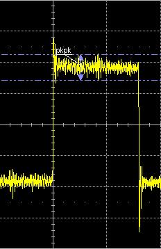
35 A series of pulses is captured on Channel 1, with vertical scaling set to 1 V/div. With 8 vertical divisions in the graticule, the screen displays 8 Volts full scale.
36 The peak-to-peak (pkpk) parameter measurement shows a value of 6.41 V for this waveform. The waveform is occupying (6.41V)/(8V) = 80.1% of full scale.
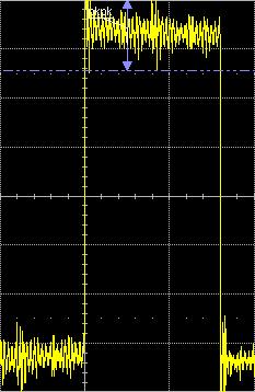
37 The noise riding on the top of the pulse can be isolated and monitored, by adjusting the measurement gates to measure pkpk on the top of the pulse only.

38 Parameter 1 (pkpk of Channel 1) is now measuring only the noise riding on the top of the pulse shown above.

39 To ensure statistical accuracy, 1000 acquisitions are taken, and the pkpk of the top of the pulse is measured each time. With vertical scaling of 1 V/div, the mean value of noise on the pulse is mv.
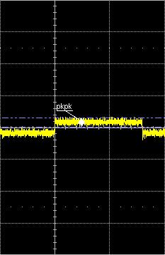
40 Changing vertical scaling to 5 V/div, the mean value of pkpk noise has now changed to V.
41 Further adjusting vertical scaling shows that channel vertical scaling significantly affects the measured noise level. At 550 mv/div, the mean noise level is 821 mv; at 2 V/div, the noise level is 1.02 V, and at 10 V/div, the noise level is 3.06V. Between 2 V/div and 10 V/div, the measured noise level tripled (factor of 3x) when changing the V/div by a factor of 5x.

42 Dynamic range also affects timing measurements. Note below the standard deviation of risetime, falltime, pulse width, and period measurements.

43 Note how changing V/div settings has affected standard deviation of timing measurements.


44 Summary: Adjusting the vertical scaling of waveforms also affects the accuracy of timing measurements.
45 Why does measurement accuracy vary with changes in V/div setting?

46 Dynamic Range When high-performance oscilloscopes acquire an input signal, the output of the amplifier is digitized by an 8-bit analog-to-digital converter (ADC). The dynamic range of the oscilloscope is the range of signal amplitudes that the ADC can process effectively. The minimum of the range occurs where signal power equals noise power. The maximum of the range occurs at or near full scale where maximum counts of the ADC are used while digitizing the waveform, while distortion is minimized. Analog-to-Digital Converter Acquisition Memory Display Amp A D C Analog Waveform Digitized Waveform Processing Trigger Circuit Oscilloscope Block Diagram
47 Practical Application: Using Multiple Channels While Maximizing Dynamic Range

48 Practical Example: Using Multiple Channels Probing four pins of a counter circuit

49 With one channel active, pulse shape view is clear
50 With two channels active, waveforms become overlapped on the display

51 With three channels overlapped in one grid, waveform shapes become difficult to distinguish
52 With four channels overlapped in one grid, waveform shapes become very difficult to distinguish
53 What happens if vertical scaling is reduced, to fit all of the waveforms into a single grid?

54 only 6 bits (64 ADC levels) used when acquiring Channel 1 8 bits (256 ADC levels) available at full scale Dynamic Range Because Channel 1 is only using ¼ of the display, only ¼ of the dynamic range of Channel 1's ADC is used when digitizing Channel 1's signal. An 8-bit ADC has 2^8 = 256 quantization levels. When using ¼ of the dynamic range, only a maximum of 64 of the 256 quantization levels are used for acquiring Channel 1. Using ¼ of quantization levels results in a maximum of 6-bit resolution on the acquired channel (2^6 = 64). This loss of resolution causes an increase in quantization noise.
55 Each channel has a separate ADC. However, because Channel 2 is only using ¼ of the display, then only ¼ of the dynamic range of Channel 2's ADC is used when digitizing Channel 2's signal. This acquisition is only using 6 bits of Channel 2's ADC, and results in a large increase in quantization noise. Dynamic Range

56 The same applies to Channels 3 and 4. When vertical scaling is reduced to fit four signals into the same grid, then each channel is only using ¼ of its dynamic range, which results in loss of vertical resolution and the addition of significant quantization noise.
57 How can the compromise between maximizing dynamic range, and clearly viewing multiple signals, be resolved? Maximize dynamic range Clearly view all signals
58 Solution: Multigrid Displays

59 Full Dynamic Range Full Dynamic Range Full Dynamic Range Multigrid Displays Using Multigrid displays, each channel is contained within a separate grid. Note that Channel 1 is fully contained within an independent grid that contains the full dynamic range of Channel 1's ADC. The same is true for Channels 2, 3, and 4. Using Multigrid, dynamic range can be optimized while all signals are clearly viewed. Full Dynamic Range

60 Selecting Multigrid Displays Signals are displayed in a single grid Signals are displayed in two grids, each with full dynamic range Signals are displayed in four grids, each with full dynamic range Signals are displayed in eight grids, each with full dynamic range Autogrid will select the optimal number of grids for the signals displayed Multigrid displays eliminate the compromise between clearly viewing multiple channels and maximizing dynamic range.

61 Single Grid Display: When using the full dynamic range, measurements are more accurate, but waveform view is not clear
62 Multigrid Display: All channels are acquired with full dynamic range. Note that measurement results have identical resolution as when using single grid display, and waveform view is much more clear.


63 Comparing Single Grid and Multigrid: Shown below, the difference in noise level is apparent when acquiring the identical signal using Single Grid and Multigrid settings. The dynamic range improvement of Multigrid significantly reduces quantization noise. Multigrid Display Single grid display
64 Viewing Quantization Noise

65 Quantization error shown when zooming at 50 mv/div. The acquired signal uses ¼ of dynamic range. Persistence is turned on, to show quantization levels
66 Quantization error shown when zooming at 50 mv/div. The acquired signal uses full dynamic range.

67 Alternately, with persistence on, acquire the signal using ¼ of the full dynamic range.
68 Then without reacquiring, change V/div setting to full dynamic range (200 mv/div). Note the quantization error shown by the persistence display.
69 Clear sweeps, then continue acquiring at with full dynamic range (200 mv/div). Note that quantization error is significantly reduced. This is because the signal is now acquired with 4x the vertical resolution, by maximizing use of the ADC's dynamic range.

70 Note statistical measurement results of pkpk, risetime, and pulse width measurements.

71 Now, change display mode to Octal Grid,

72 Measurement result accuracy remains identical when using Octal Grid. In both cases, dynamic range and vertical resolution are maximized.

73 Real Application: Using Octal Grid to View Multizoomed Data Burst at a 250,000:1 ratio CDMA Burst Zoom 1,000:1 Zoom 10:1 Zoom 5,000:1 Zoom 50:1 Zoom 50,000:1 Zoom 500:1 Zoom 250,000:1
74 Reference Slides
75 Transient Testing (Automotive) Pulse Characteristics Capacitive load dump Inductive kickback/spike (back EMF from motor turn off) Measurement Needs Capture Time longer the better: Relay bounce (µs to ms) Transient time µs (motor) ns (FET switch) Measure MHz transient 10s capture = 2Mpts at 100 MHz Sample Rate
76 Dropout and Interrupt Testing Monitor AC or DC voltage line with oscilloscope during EMC testing Verify that dropout or interrupt occurred, and that device under test was unaffected
77 Surge Testing Pulse Characteristics T rise = typically 1.2 to 10 µs T fall = typically 20 to 10,000µs Measurement Needs Capture a Single Pulse Measure one pulse, verify rise and fall time
78 Standard scope measurements revert to peak-to-peak if Top and Base are not found. (Compare risetime value below to risetime value in next slide.)
79 Standard scope measurements revert to peak-to-peak if Top and Base are not found. (Compare risetime value below to risetime value in previous slide.)
80 Effect of thresholds on the Width measurement of this ESD pulse
81 Effect of thresholds on the Width measurement of this ESD pulse
82 Effect of thresholds on the Width measurement of this ESD pulse
83 The pulse width and risetime are measured, both with and without EMC thresholds applied. In parameter 1 (P1), the thresholds are set to 0% - Max, and the pulse width is measured correctly as nanoseconds. In parameter 2 (P2), the thresholds are set to the standard scope threshold of 50% of Top and Base. In this case, the measurement is incorrectly reported as nanoseconds -- an error of 2287%. The width measurement was impacted so significantly, that the 50% threshold between Top and Base actually produced a width measurement on the wrong pulse shape. Parameter 3 (P3) is set to the correct EMC threshold of 0% to Max, producing a correct electrostatic pulse risetime measurement of 833 picoseconds. Notice that in parameter 4 (P4), the standard risetime is incorrectly reported as 873 picoseconds. When using standard pulse parameter measurements, erroneous values can be obtained.
, the thresholds are set to the standard scope threshold of 50% of Top and Base. In this case, the measurement is incorrectly reported as 50.")
84 The pulse width and risetime are measured, both with and without EMC thresholds applied. In parameter 1 (P1), the thresholds are set to 0% - Max, and the pulse width is measured correctly as nanoseconds. In parameter 2 (P2), the thresholds are set to the standard scope threshold of 50% of Top and Base. In this case, the measurement is incorrectly reported as nanoseconds -- an error of 2287%. The width measurement was impacted so significantly, that the 50% threshold between Top and Base actually produced a width measurement on the wrong pulse shape. Parameter 3 (P3) is set to the correct EMC threshold of 0% to Max, producing a correct electrostatic pulse risetime measurement of 833 picoseconds. Notice that in parameter 4 (P4), the standard risetime is incorrectly reported as 873 picoseconds. When using standard pulse parameter measurements, erroneous values can be obtained.
85 The pulse width and risetime are measured, both with and without EMC thresholds applied. In parameter 1 (P1), the thresholds are set to 0% - Max, and the pulse width is measured correctly as nanoseconds. In parameter 2 (P2), the thresholds are set to the standard scope threshold of 50% of Top and Base. In this case, the measurement is incorrectly reported as nanoseconds -- an error of 2287%. The width measurement was impacted so significantly, that the 50% threshold between Top and Base actually produced a width measurement on the wrong pulse shape. Parameter 3 (P3) is set to the correct EMC threshold of 0% to Max, producing a correct electrostatic pulse risetime measurement of 833 picoseconds. Notice that in parameter 4 (P4), the standard risetime is incorrectly reported as 873 picoseconds. When using standard pulse parameter measurements, erroneous values can be obtained.
86 The pulse width and risetime are measured, both with and without EMC thresholds applied. In parameter 1 (P1), the thresholds are set to 0% - Max, and the pulse width is measured correctly as nanoseconds. In parameter 2 (P2), the thresholds are set to the standard scope threshold of 50% of Top and Base. In this case, the measurement is incorrectly reported as nanoseconds -- an error of 2287%. The width measurement was impacted so significantly, that the 50% threshold between Top and Base actually produced a width measurement on the wrong pulse shape. Parameter 3 (P3) is set to the correct EMC threshold of 0% to Max, producing a correct electrostatic pulse risetime measurement of 833 picoseconds. Notice that in parameter 4 (P4), the standard risetime is incorrectly reported as 873 picoseconds. When using standard pulse parameter measurements, erroneous values can be obtained.
, the thresholds are set to the standard scope threshold of 50% of Top and Base. In this case, the measurement is incorrectly reported as 50.")
87 The pulse width and risetime are measured, both with and without EMC thresholds applied. In parameter 1 (P1), the thresholds are set to 0% - Max, and the pulse width is measured correctly as nanoseconds. In parameter 2 (P2), the thresholds are set to the standard scope threshold of 50% of Top and Base. In this case, the measurement is incorrectly reported as nanoseconds -- an error of 2287%. The width measurement was impacted so significantly, that the 50% threshold between Top and Base actually produced a width measurement on the wrong pulse shape. Parameter 3 (P3) is set to the correct EMC threshold of 0% to Max, producing a correct electrostatic pulse risetime measurement of 833 picoseconds. Notice that in parameter 4 (P4), the standard risetime is incorrectly reported as 873 picoseconds. When using standard pulse parameter measurements, erroneous values can be obtained.
EMC / ESD Pulse Measurements Using Oscilloscopes September /16/$ IEEE
 EMC / ESD Pulse Measurements Using Oscilloscopes September 2016 978-1-5090-1416-3/16/$31.00 2016 IEEE Contents EMC Measurement Categories and Requirements ESD Pulse Test Requirements and Measurement Thresholds
Appendix A: Specifications
 All specifications apply to the TDS 200-Series Digital Oscilloscopes and a P2100 probe with the Attenuation switch set to 10X unless noted otherwise. To meet specifications, two conditions must first be
N acquisitions, all channels simultaneously, N is selectable from 4, 16, 64, and 128 Inputs
 With compliments All specifications apply to the TDS 200-Series Digital Real-Time Oscilloscope with a P2100 probe with the Attenuation switch set to 10X unless noted otherwise. To meet specifications,
SiTime University Turbo Seminar Series
 SiTime University Turbo Seminar Series How to Measure Clock Jitter Part I Principle and Practice April 8-9, 2013 Agenda Jitter definitions and terminology Who cares about jitter How to measure clock jitter
Immunity Testing for the CE Mark
 Immunity Testing for the CE Mark Summary The European Union (EU) currently has 25 member countries with 2 additional countries to be added in 2007. The total population at that time will be nearly a half
EMC standards. Presented by: Karim Loukil & Kaïs Siala
 Training Course on Conformity and Interoperability on Type Approval testing for Mobile Terminals, Homologation Procedures and Market Surveillance, Tunis-Tunisia, from 20 to 24 April 2015 EMC standards
2620 Modular Measurement and Control System
 European Union (EU) Council Directive 89/336/EEC Electromagnetic Compatibility (EMC) Test Report 2620 Modular Measurement and Control System Sensoray March 31, 2006 April 4, 2006 Tests Conducted by: ElectroMagnetic
Rohde & Schwarz EMI/EMC debugging with modern oscilloscope. Ing. Leonardo Nanetti Rohde&Schwarz
 Rohde & Schwarz EMI/EMC debugging with modern oscilloscope Ing. Leonardo Nanetti Rohde&Schwarz EMI debugging Agenda l The basics l l l l The idea of EMI debugging How is it done? Application example What
2 Operation. Operation. Getting Started
 2 Operation Operation Getting Started Access the Ethernet Package by pressing the ANALYSIS PACKAGES button (MATH on LC scopes). A menu showing all the packages installed on the DSO is displayed. Select
Jitter Analysis Techniques Using an Agilent Infiniium Oscilloscope
 Jitter Analysis Techniques Using an Agilent Infiniium Oscilloscope Product Note Table of Contents Introduction........................ 1 Jitter Fundamentals................. 1 Jitter Measurement Techniques......
2520 Pulsed Laser Diode Test System
 Complete pulse test of laser diode bars and chips with dual photocurrent measurement channels 0 Pulsed Laser Diode Test System Simplifies laser diode L-I-V testing prior to packaging or active temperature
Advanced Test Equipment Rentals ATEC (2832)
") Established 1981 Advanced Test Equipment Rentals www.atecorp.com 800-404-ATEC (2832) Downloaded from http://www.everyspec.com DEPARTMENT OF DEFENSE INTERFACE STANDARD METRIC 22 MARCH 2013 SUPERSEDING MIL-STD-1275D
Established 1981 Advanced Test Equipment Rentals www.atecorp.com 800-404-ATEC (2832) Downloaded from http://www.everyspec.com DEPARTMENT OF DEFENSE INTERFACE STANDARD METRIC 22 MARCH 2013 SUPERSEDING MIL-STD-1275D
A Comparison Between MIL-STD and Commercial EMC Requirements Part 2. By Vincent W. Greb President, EMC Integrity, Inc.
 A Comparison Between MIL-STD and Commercial EMC Requirements Part 2 By Vincent W. Greb President, EMC Integrity, Inc. OVERVIEW Compare and contrast military (i.e., MIL-STD) and commercial EMC immunity
Contents. ZT530PCI & PXI Specifications. Arbitrary Waveform Generator. 16-bit, 400 MS/s, 2 Ch
 ZT530PCI & PXI Specifications Arbitrary Waveform Generator 16-bit, 400 MS/s, 2 Ch Contents Outputs... 2 Digital-to-Analog Converter (DAC)... 3 Internal DAC Clock... 3 Spectral Purity... 3 External DAC
Contents. 1 Introduction. 2 System-Level Electrostatic Discharge (ESD) and Electrical Fast Transient. 3 Electromagnetic Interference
 and Electrical Fast Transient. 3 Electromagnetic Interference") Issue 3, October 2002 Electromagnetic Compatibility and Electrical Safety Contents Telcordia GR-1089 - Documentation Information Generic Requirements Notice Of Disclaimer................. iii Contents.......................................
Issue 3, October 2002 Electromagnetic Compatibility and Electrical Safety Contents Telcordia GR-1089 - Documentation Information Generic Requirements Notice Of Disclaimer................. iii Contents.......................................
An Introduction to EMC Testing (what can be done with scopes) Vincent Lascoste EMC Product Manager - RSF
 Vincent Lascoste EMC Product Manager - RSF") An Introduction to EMC Testing (what can be done with scopes) Vincent Lascoste EMC Product Manager - RSF Definition of ElectroMagnetic Compatibility (EMC) EMC is defined as: "The ability of devices and
An Introduction to EMC Testing (what can be done with scopes) Vincent Lascoste EMC Product Manager - RSF Definition of ElectroMagnetic Compatibility (EMC) EMC is defined as: "The ability of devices and
Transient Data Acquisition System, TAS 4-40 Potential-free measurement of fast rise pulses:
 Transient Data Acquisition System, TAS 4-40 Potential-free measurement of fast rise pulses: High precision measurement of fast rising voltages and currents causes considerable problems in many spheres
54645D. Mixed Signal Oscilloscope
 54645D Mixed Signal Oscilloscope Page 1 of 42 Instructions for the use of the 54645D Mixed Signal Oscilloscope This pamphlet is intended to give you (the student) an overview on the use of the 54645D Mixed
Characterizing High-Speed Oscilloscope Distortion A comparison of Agilent and Tektronix high-speed, real-time oscilloscopes
 Characterizing High-Speed Oscilloscope Distortion A comparison of Agilent and Tektronix high-speed, real-time oscilloscopes Application Note 1493 Table of Contents Introduction........................
Measurement and Analysis for Switchmode Power Design
 Measurement and Analysis for Switchmode Power Design Switched Mode Power Supply Measurements AC Input Power measurements Safe operating area Harmonics and compliance Efficiency Switching Transistor Losses
Contents. M-Class Oscilloscope Specifications PCI, PXI, VXI, & LAN. ZT4610 Series: 8-bit, 4 GS/s, 1 GHz, 2 or 4 Ch
 M-Class Oscilloscope Specifications PCI, PXI, VXI, & LAN ZT4610 Series: 8-bit, 4 GS/s, 1 GHz, 2 or 4 Ch ZT4210 Series: 8-bit, 1 GS/s, 300 MHz, 2 or 4 Ch Contents Acquisition...2 Vertical...3 Horizontal...7
HP 16533A 1-GSa/s and HP 16534A 2-GSa/s Digitizing Oscilloscope
 User s Reference Publication Number 16534-97009 February 1999 For Safety Information, Warranties, and Regulatory Information, see the pages behind the Index Copyright Hewlett-Packard Company 1991 1999
CHAPTER 6 EMI EMC MEASUREMENTS AND STANDARDS FOR TRACKED VEHICLES (MIL APPLICATION)
") 147 CHAPTER 6 EMI EMC MEASUREMENTS AND STANDARDS FOR TRACKED VEHICLES (MIL APPLICATION) 6.1 INTRODUCTION The electrical and electronic devices, circuits and systems are capable of emitting the electromagnetic
147 CHAPTER 6 EMI EMC MEASUREMENTS AND STANDARDS FOR TRACKED VEHICLES (MIL APPLICATION) 6.1 INTRODUCTION The electrical and electronic devices, circuits and systems are capable of emitting the electromagnetic
Switched Mode Power Supply Measurements
 Power Analysis 1 Switched Mode Power Supply Measurements AC Input Power measurements Safe operating area Harmonics and compliance Efficiency Switching Transistor Losses Measurement challenges Transformer
Table of Contents. 1 Introduction. 2 System-Level Electrostatic Discharge (ESD) and Electrical Fast Transient (EFT) 3 Electromagnetic Interference
 and Electrical Fast Transient (EFT) 3 Electromagnetic Interference") Electromagnetic Compatibility and Electrical Safety GR-1089-CORE Table of Contents Table of Contents 1 Introduction 1.1 Purpose and Scope.................................. 1 1 1.2 Items Not Covered in
Electromagnetic Compatibility and Electrical Safety GR-1089-CORE Table of Contents Table of Contents 1 Introduction 1.1 Purpose and Scope.................................. 1 1 1.2 Items Not Covered in
FISCHER CUSTOM COMMUNICATIONS, INC.
 FISCHER CUSTOM COMMUNICATIONS, INC. Current Probe Catalog FISCHER CUSTOM COMMUNICATIONS, INC. Fischer Custom Communications, Inc., is a manufacturer of custom electric and magnetic field sensors for military
DesignCon Noise Injection for Design Analysis and Debugging
 DesignCon 2009 Noise Injection for Design Analysis and Debugging Douglas C. Smith, D. C. Smith Consultants [Email: doug@dsmith.org, Tel: 408-356-4186] Copyright! 2009 Abstract Troubleshooting PCB and system
EMC TEST REPORT For MPP SOLAR INC Inverter/ Charger Model Number : PIP 4048HS
 EMC-E20130903E EMC TEST REPORT For MPP SOLAR INC Inverter/ Charger Model Number : PIP 4048HS Prepared for : MPP SOLAR INC Address : 4F, NO. 50-1, SECTION 1, HSIN-SHENG S. RD. TAIPEI, TAIWAN Prepared by
Testing Sensors & Actors Using Digital Oscilloscopes
 Testing Sensors & Actors Using Digital Oscilloscopes APPLICATION BRIEF February 14, 2012 Dr. Michael Lauterbach & Arthur Pini Summary Sensors and actors are used in a wide variety of electronic products
How to Setup a Real-time Oscilloscope to Measure Jitter
 TECHNICAL NOTE How to Setup a Real-time Oscilloscope to Measure Jitter by Gary Giust, PhD NOTE-3, Version 1 (February 16, 2016) Table of Contents Table of Contents... 1 Introduction... 2 Step 1 - Initialize
LeCroy 9304A, 9304AM Digital Oscilloscopes 200 MHz Bandwidth, 100 MS/s. Main Features
 LeCroy 9304A, 9304AM Digital Oscilloscopes 200 MHz Bandwidth, 100 MS/s Main Features Four Channels 50k and 200k Point Records DOS Compatible Floppy Disk, PCMCIA portable hard drive and Memory Card Options
EMC Seminar Series All about EMC Testing and Measurement Seminar 1
 EMC Seminar Series All about EMC Testing and Measurement Seminar 1 Introduction to EMC Conducted Immunity Jeffrey Tsang Organized by : Department of Electronic Engineering 1 Basic Immunity Standards: IEC
Arbitrary/Function Waveform Generators 4075B Series
 Data Sheet Arbitrary/Function Waveform Generators Point-by-Point Signal Integrity The Arbitrary/Function Waveform Generators are versatile high-performance single- and dual-channel arbitrary waveform generators
High precision measurement system for current and voltage IHC-A/B-RM01/03
 Measurement Offset-free and low-noise 16 bit data acquisition system ISA-ASIC Internal sample rate 3,500 Hz Communication Standard RS232- or RS485 interface Advantages Direct measurement on the bus bar
Scale Manufacturers Association (SMA) Recommendation on. Electrical Disturbance
 Recommendation on. Electrical Disturbance") Scale Manufacturers Association (SMA) Recommendation on Electrical Disturbance (SMA RED-0499) Provisional First Edition Approved by SMA Pending Final Comment April 24, 1999 Copyright: SMA, April, 1999
Scale Manufacturers Association (SMA) Recommendation on Electrical Disturbance (SMA RED-0499) Provisional First Edition Approved by SMA Pending Final Comment April 24, 1999 Copyright: SMA, April, 1999
DTE Power via MDI Task Force P802.3af
 DTE Power via MDI Task Force P802.3af AC Disconnect Detection Ad Hoc EN55024 Test Results A.1.4.3 Paul Scott, Norbert Kukta, Scott Burton 10 May 2002 Objectives Determine which EN55024 tests are relevant
Application Note 5044
 HBCU-5710R 1000BASE-T Small Form Pluggable Low Voltage (3.3V) Electrical Transceiver over Category 5 Unshielded Twisted Pair Cable Characterization Report Application Note 5044 Summary The Physical Medium
z475 Remote DC Power Supply Preliminary
 TECHNICAL SPECIFICATIONS z475 Remote DC Power Supply Preliminary 2018 LitePoint, A Teradyne Company. All rights reserved. Overview The z475 remote DC Power supply can provide a stable VCC voltage for PA/FEM/SW
Emerging Standards for EMC Emissions & Immunity
 Emerging Standards for EMC Emissions & Immunity Requirements for Industrial, Scientific, Medical & Information Technology Equipment CE Marking requirements are the path to increased market access Powerful
Techniques to reduce electromagnetic noise produced by wired electronic devices
 Rok / Year: Svazek / Volume: Číslo / Number: Jazyk / Language 2016 18 5 EN Techniques to reduce electromagnetic noise produced by wired electronic devices - Tomáš Chvátal xchvat02@stud.feec.vutbr.cz Faculty
Device Detection and Monitoring of Unintentional Radiated Emissions
 Clemson Vehicular Electronics Laboratory Automotive EMC Workshop Capable and Reliable Electronic Systems Design October 5, 212 Device Detection and Monitoring of Unintentional Radiated Emissions Todd Hubing
LeCroy 9384 Series Digital Oscilloscope 1 GHz Bandwidth, 1-4 GS/s
 LeCroy 9384 Series Digital Oscilloscope 1 GHz Bandwidth, 1-4 GS/s Main Features 1 GHz Bandwidth Sample rates to 4 Gigasamples/second Memory lengths to 8M points 8-bit vertical resolution, 11 with ERES
Multi-function (MI, ME, M2, M1) 2 NO (2 SPST-NO) 12 / / 400 3,000 1, / 0.3 / (5 / 5) AgNi
 2 NO (2 SPST-NO) 12 / / 400 3,000 1, / 0.3 / (5 / 5) AgNi") Features Special relay for alternating loads, for applications with pumps, compressors, air conditioning or refrigeration units 2 independent NO output, 12 A 4 functions 2 independent control signals,
Features Special relay for alternating loads, for applications with pumps, compressors, air conditioning or refrigeration units 2 independent NO output, 12 A 4 functions 2 independent control signals,
MSO Supplied with a full SDK including example programs Software compatible with Windows XP, Windows Vista and Windows 7 Free Technical Support
 PicoScope 2205 MSO USB-POWERED MIXED SIGNAL OSCILLOSCOPE Think logically... 25 MHz analog bandwidth 100 MHz max. digital input frequency 200 MS/s mixed signal sampling Advanced digital triggers SDK and
Partners for HV and EMC Solutions MIL-STD-461 G. Partners for HV and EMC Solutions
 MIL-STD-461 G 1 MIL-STD-461 G 2 MIL-STD-461 G 2015 Current Version Superseding Back Ground MIL-STD-461F (2007) MIL-STD-461E (1999) Test Methods and Limits MIL-STD-461D (1993) Test Limits MIL-STD-462D (1993)
One-day Conference 18 March Power Supply, EMC and Signalling, in Railway Systems
 One-day Conference 18 March 2017 Power Supply, EMC and Signalling, in Railway Systems EMC Management and Related Technical Aspects in Railway Systems By Dr Peter S W LEUNG http://www.ee.cityu.edu.hk/~pswleung/
Chapter 2 Analog-to-Digital Conversion...
 Chapter... 5 This chapter examines general considerations for analog-to-digital converter (ADC) measurements. Discussed are the four basic ADC types, providing a general description of each while comparing
Correlation Considerations: Real HBM to TLP and HBM Testers
 Correlation Considerations: Real HBM to TLP and HBM Testers Jon Barth, John Richner Barth Electronics, Inc., 1589 Foothill Drive, Boulder City, NV 89005 USA tel.: (702)- 293-1576, fax: (702)-293-7024,
Advanced Test Equipment Rentals ATEC (2832)
") Established 1981 Advanced Test Equipment Rentals www.atecorp.com 800-404-ATEC (2832) Page 1 of 8 9350A Family Digital Oscilloscopes 500 MHz Bandwidth, 2 GS/s Main Features Two and Four Channel versions
Established 1981 Advanced Test Equipment Rentals www.atecorp.com 800-404-ATEC (2832) Page 1 of 8 9350A Family Digital Oscilloscopes 500 MHz Bandwidth, 2 GS/s Main Features Two and Four Channel versions
MIL-STD-883E METHOD 3024 SIMULTANEOUS SWITCHING NOISE MEASUREMENTS FOR DIGITAL MICROELECTRONIC DEVICES
 SIMULTANEOUS SWITCHING NOISE MEASUREMENTS FOR DIGITAL MICROELECTRONIC DEVICES 1. Purpose. This method establishes the procedure for measuring the ground bounce (and V CC bounce) noise in digital microelectronic
Harmonizing the ANSI-C12.1(2008) EMC Tests. Harmonizing the ANSI-C12.1(2008) EMC Tests
 EMC Tests. Harmonizing the ANSI-C12.1(2008) EMC Tests") Harmonizing the ANSI-C12.1(2008) EMC Tests Subcommittee 1 (Emissions) Subcommittee 5 (Immunity) Joint Task Force on C12.1 June 17, 2013 1 The Accredited Standards Committee C63 presents Harmonizing the
Harmonizing the ANSI-C12.1(2008) EMC Tests Subcommittee 1 (Emissions) Subcommittee 5 (Immunity) Joint Task Force on C12.1 June 17, 2013 1 The Accredited Standards Committee C63 presents Harmonizing the
Surge Coupling Decoupling Network (S-CDN) Considerations
 Considerations") Surge Coupling Decoupling Network (S-CDN) Considerations Introduction Surge Coupling-Decoupling Networks (SCDN) are used to couple the surge specified in IEC 61000-4-5 onto active telecom lines to determine
Surge Coupling Decoupling Network (S-CDN) Considerations Introduction Surge Coupling-Decoupling Networks (SCDN) are used to couple the surge specified in IEC 61000-4-5 onto active telecom lines to determine
CONNECTING THE PROBE TO THE TEST INSTRUMENT
 2SHUDWLRQ 2SHUDWLRQ Caution The input circuits in the AP034 Active Differential Probe incorporate components that protect the probe from damage resulting from electrostatic discharge (ESD). Keep in mind
Today most of engineers use oscilloscope as the preferred measurement tool of choice when it comes to debugging and analyzing switching power
 Today most of engineers use oscilloscope as the preferred measurement tool of choice when it comes to debugging and analyzing switching power supplies. In this session we will learn about some basics of
EMC Test report for LED Panel Light Models , , , , ,
 4326247.50 EMC Test report for LED Panel Light Models 000529, 000530, 000531, 000532, 000535, 000536 Guangzhou, date of issue: 2016-02-24 Author:Jazz Liang By order of Marvo Verlichting B.V. at Hoogeveen,
AC Current Probes CT1 CT2 CT6 Data Sheet
 View at www.testequipmentdepot.com AC Current Probes CT1 CT2 CT6 Data Sheet Features & Benefits High Bandwidth Ultra-low Inductance Very Small Form Factor Characterize Current Waveforms up to
Harmonic Current emission EN :2014 Class A Pass. Voltage Fluctuation and Flicker EN :2013 Clause 5 Pass
 Reference No.: WTS15F0323845E Page 2 of 33 1 Test Summary Test Item Mains Terminal Disturbance Voltage, 148.5kHz to 30MHz Disturbance Power, 30MHz to 300MHz Discontinuous Disturbance (Click) Radiated Emission,
HEC-45LTN-45PFAS Rev A
 A. Features High Efficiency (Up to 85%). Active Power Factor Correction (Typical 0.96). Isolation Class II. All-Round Protection: OVP/SCP/OPP. Fully isolated plastic case with IP20 and dry location. Class
W5500 Compliance Test Report
 W5500 Compliance Test Report Version 1.0.0 http://www.wiznet.co.kr Copyright 2015 WIZnet Co., Ltd. All rights reserved. Table of Contents 1 802.3 10Base-T compliance tests... 5 1.1 Overview... 5 1.2 Testing
DOBLE F6150e TECHNICAL SPECIFICATIONS
 DOBLE F6150e TECHNICAL SPECIFICATIONS The F6150e line of System Simulators is designed for simulation tests on relay and protection schemes. There are four distinct models for your specific testing needs.
Discontinuous Disturbance (Click) EN :2006+A1:2009+A2:2011 Clause N/A** Radiated Emission, 30MHz to 1000MHz
 EN :2006+A1:2009+A2:2011 Clause N/A** Radiated Emission, 30MHz to 1000MHz") Reference No.: WTN13F0706038E Page 2 of 40 1 Test Summary Test Item Mains Terminal Disturbance Voltage, 148.5kHz to 30MHz Disturbance Power, 30MHz to 300MHz EMISSION Test Standard Class / Severity Result
Reference No.: WTN13F0706038E Page 2 of 40 1 Test Summary Test Item Mains Terminal Disturbance Voltage, 148.5kHz to 30MHz Disturbance Power, 30MHz to 300MHz EMISSION Test Standard Class / Severity Result
Getting Started. MSO/DPO Series Oscilloscopes. Basic Concepts
 Getting Started MSO/DPO Series Oscilloscopes Basic Concepts 001-1523-00 Getting Started 1.1 Getting Started What is an oscilloscope? An oscilloscope is a device that draws a graph of an electrical signal.
Cost effective method to locate the vulnerable nodes of circuits against the electrical fast transients
 Journal of Electrical and Electronic Engineering 2015; 3(2-1): 72-77 Published online February 9, 2015 (http://www.sciencepublishinggroup.com/j/jeee) doi: 10.11648/j.jeee.s.2015030201.26 ISSN: 2329-1613
EMI Test Receivers: Past, Present and Future
 EM Test Receivers: Past, Present and Future Andy Coombes EMC Product Manager Rohde & Schwarz UK Ltd 9 th November 2016 ntroduction ı Andy Coombes EMC Product Manager ı 20 years experience in the field
Wave Inspector Navigation and Search: Simplifying Waveform Analysis
 Wave Inspector Navigation and Search: Simplifying Waveform Analysis Our thanks to Tektronix for allowing us to reprint the following article. Introduction As Moore s Law pushes electronic technology faster,
Use optocouplers for safe and reliable electrical systems
 1 di 5 04/01/2013 10.15 Use optocouplers for safe and reliable electrical systems Harold Tisbe, Avago Technologies Inc. 1/2/2013 9:06 AM EST Although there are multiple technologies--capacitive, magnetic,
Tektronix: Products > AWG 2040 Arbitrary Waveform Generator
 Page 1 of 7 Arbitrary Waveform Generator AWG 2040 This product is no longer carried in our catalog. Features 1.024 GS/sec Clock Rate Provides up to 500 MHz Waveforms 1 MB Record Length (4 MB with Opt.
SERVOSTAR S- and CD-series Sine Encoder Feedback
 SERVOSTAR S- and CD-series Sine Encoder Feedback The SERVOSTAR S and SERVOSTAR CD family of drives offers the ability to accept signals from various feedback devices. Sine Encoders provide analog-encoded
By order of American Power Conversion Holdings Inc. at New Taipei City, Taiwan
 4322705.50 EMC Test report for Plug-in adaptor Models PM1W-IT, PM1WU2-IT, PM1W-GR, PM1W-SP, PM1W-RS, PM1WB-RS, PM1WU2-GR, PM1WU2-SP, PM1WU2-RS, PM1WBU2-RS, PM1W-UK, PM1WU2-UK, PM1W-FR, PM1WU2-FR Guangzhou,
Manual Supplement. This supplement contains information necessary to ensure the accuracy of the above manual.
 Manual Title: 5502E Getting Started Supplement Issue: 3 Part Number: 4155211 Issue Date: 9/18 Print Date: November 2012 Page Count: 12 Revision/Date: This supplement contains information necessary to ensure
PC-OSCILLOSCOPE PCS500. Analog and digital circuit sections. Description of the operation
 PC-OSCILLOSCOPE PCS500 Analog and digital circuit sections Description of the operation Operation of the analog section This description concerns only channel 1 (CH1) input stages. The operation of CH2
Passive Current Transducers for Sinusoidal Alternate Currents From A/0...5 A MCR-SLP-1/5-UI-0(-SW)
") Passive Current Transducers for Sinusoidal Alternate Currents From 0... A/0...5 A (-SW) Passive current transducer without power supply Measuring range A and 5 A AC, reconnectable Available with threshold
Passive Current Transducers for Sinusoidal Alternate Currents From 0... A/0...5 A (-SW) Passive current transducer without power supply Measuring range A and 5 A AC, reconnectable Available with threshold
Schedule of Accreditation issued by United Kingdom Accreditation Service 2 Pine Trees, Chertsey Lane, Staines-upon-Thames, TW18 3HR, UK
 2 Pine Trees, Chertsey Lane, Staines-upon-Thames, TW18 3HR, UK Caddsdown Industrial Estate Clovelly Road Bideford Devon EX39 3DX Contact: Becky Scott Tel: +44 (0)1237 423388 Fax: +44 (0)1237 423434 E-Mail:
BS EN TESTS ON THE IT TOXIC GAS DETECTOR MODULE
 Page 1 of 18 Interference Testing And Consultancy Services (Pty) Ltd ITC SERVICES (PTY) LTD Reg 88/002032/07 Plot 44 Kameeldrift East, Pretoria Private Bag X13 Lynn East 0039 Republic of South Africa Tel
Report for Excelsys EMC Measurements for 4Xgen Purchase Order: Project Number EMT07J026 Rev. B
 Report for Excelsys on EMC Measurements for 4Xgen Purchase Order: Project Number EMT07J026 Rev. B Rev Date Comment A April 2007 Change in DoC content B May 2007 Added Immunity Section EMT is a TÜV Appointed
PGB2 Series Halogen Free / Lead-Free
 Halogen Free / Lead-Free Description PulseGuard ESD Suppressors help protect sensitive electronic equipment against electrostatic discharge (ESD). They use polymer composite materials to suppress fastrising
Test Report. Guangdong East Power Co., Ltd. Fully Automatic AC Voltage Regulator. Brand Name:
 Test Report Applicant: Product Name: Brand Name: Model No.: Guangdong East Power Co., Ltd. Fully Automatic AC Voltage Regulator EAST ZTY-30KVA Date of Receipt : Aug. 30, 2013 Date of Test: Sep. 03, 2013
Overcurrent Protection / 7SJ45
 Overcurrent Protection / SJ SIPROTEC easy SJ numerical overcurrent protection relay powered by CTs Fig. / Description SIPROTEC easy SJ numerical overcurrent protection relay powered by current transformers
Getting the most out of your Measurements Workshop. Mike Schnecker
 Getting the most out of your Measurements Workshop Mike Schnecker Agenda Oscilloscope Basics Using a RTE1000 Series Oscilloscope. Probing Basics Passive probe compensation Ground lead effects Vertical
Manual Supplement. This supplement contains information necessary to ensure the accuracy of the above manual.
 Manual Title: 550A Getting Started Supplement Issue: Part Number: 415509 Issue Date: 9/18 Print Date: November 01 Page Count: 19 Revision/Date: This supplement contains information necessary to ensure
Overview of EMC Regulations and Testing. Prof. Tzong-Lin Wu Department of Electrical Engineering National Taiwan University
 Overview of EMC Regulations and Testing Prof. Tzong-Lin Wu Department of Electrical Engineering National Taiwan University What is EMC Electro-Magnetic Compatibility ( 電磁相容 ) EMC EMI (Interference) Conducted
~W~~~ Laboratory Accreditation Program
 ~ ~.en) National Voluntary ~W~~~ Laboratory Accreditation Program SCOPE OF ACCREDITATION TO ISO/IEC 17025:2005 Dayton T. Brown, Inc. 1195 Church Street Bohemia, NY 11716 Ms. Mary Alice Der Aris Phone:
BS EN TESTS ON THE RS-485 FFP2 THE BRAIN REVISION C
 Page 1 of 23 Interference Testing And Consultancy Services (Pty) Ltd ITC SERVICES (PTY) LTD Reg 88/002032/07 Plot 44 Kameeldrift East, Pretoria Private Bag X13 Lynn East 0039 Republic of South Africa Tel
EN61326 EMC COMPLIANCE REPORT on the LP Series Ultrasonic Transmitter Remote Amplifier and Transducer for Hawk Measurement Systems Pty Ltd
 Page 1 of 15 EMC Technologies Pty Ltd ABN 82 057 105 549 57 Assembly Drive Tullamarine Victoria Australia 3043 Ph: + 613 9335 3333 Fax: + 613 9338 9260 email: melb@emctech.com.au EN61326 EMC COMPLIANCE
PQ Monitoring Standards
 Characterization of Power Quality Events Charles Perry, EPRI Chair, Task Force for PQ Characterization E. R. Randy Collins, Clemson University Chair, Working Group for Monitoring Electric Power Quality
Downloaded from 1. THE FOLLOWING PAGES OF MIL-STD-462D HAVE BEEN REVISED AND SUPERSEDE THE PAGES LISTED:
 NOTICE OF CHANGE METRIC 10 April 1995 MILITARY STANDARD MEASUREMENT OF ELECTROMAGNETIC INTERFERENCE CHARACTERISTICS TO ALL HOLDERS OF : 1. THE FOLLOWING PAGES OF HAVE BEEN REVISED AND SUPERSEDE THE PAGES
Implementing Automated Oscilloscope Calibration Systems
 This paper was first presented at the National Conference of Standards Laboratories '97, Atlanta, Georgia, USA, on July 28, 1997. Implementing Automated Oscilloscope Calibration Systems Presenter: Richard
HEC-35LTA-XXTSAA Rev A
 A. Features High Efficiency (Up to 87%). Active Power Factor Correction (Typical 0.95). Isolation Class II. All-Round Protection: OVP/SCP/OTP/OPP. Fully isolated plastic case with IP20 and dry location.
Report for Excelsys EMC Measurements for 6Xgen Purchase Order: by Project Number EMT08J027
 Report for Excelsys on EMC Measurements for 6Xgen Purchase Order: by email Project Number EMT08J027 Tom O Brien, Engineering Director ElectroMagnetic Technologies Ltd, Cork, June 2007 Executive Summary
Automotive Surge Suppression Devices Can Be Replaced with High Voltage IC
 Automotive Surge Suppression Devices Can Be Replaced with High Voltage IC By Bruce Haug, Senior Product Marketing Engineer, Linear Technology Background Truck, automotive and heavy equipment environments
Digital Debug With Oscilloscopes Lab Experiment
 Digital Debug With Oscilloscopes A collection of lab exercises to introduce you to digital debugging techniques with a digital oscilloscope. Revision 1.0 Page 1 of 23 Revision 1.0 Page 2 of 23 Copyright
Improving CDM Measurements With Frequency Domain Specifications
 Improving CDM Measurements With Frequency Domain Specifications Jon Barth (1), Leo G. Henry Ph.D (2), John Richner (1) (1) Barth Electronics, Inc, 1589 Foothill Drive, Boulder City, NV 89005 USA tel.:
Combination Wave Test System
 Immunity Tests Combination Wave Test System Brief Overview of Phenomena............... 2 Applicable Standards................... 3 Test System Overview.................. 4 Generator Specifications.................
Test and Measurement for EMC
 Test and Measurement for EMC Bogdan Adamczyk, Ph.D., in.c.e. Professor of Engineering Director of the Electromagnetic Compatibility Center Grand Valley State University, Michigan, USA Ottawa, Canada July
PESD1LIN. 1. Product profile. LIN bus ESD protection diode in SOD General description. 1.2 Features. 1.3 Applications. Quick reference data
 Rev. 01 26 October 2004 Product data sheet 1. Product profile 1.1 General description in very small SOD323 (SC-76) SMD plastic package designed to protect one automotive LIN bus line from the damage caused
TAKE THE MYSTERY OUT OF PROBING. 7 Common Oscilloscope Probing Pitfalls to Avoid
 TAKE THE MYSTERY OUT OF PROBING 7 Common Oscilloscope Probing Pitfalls to Avoid Introduction Understanding common probing pitfalls and how to avoid them is crucial in making better measurements. In an
Multiple Instrument Station Module
 Multiple Instrument Station Module Digital Storage Oscilloscope Vertical Channels Sampling rate Bandwidth Coupling Input impedance Vertical sensitivity Vertical resolution Max. input voltage Horizontal
Combinational logic: Breadboard adders
 ! ENEE 245: Digital Circuits & Systems Lab Lab 1 Combinational logic: Breadboard adders ENEE 245: Digital Circuits and Systems Laboratory Lab 1 Objectives The objectives of this laboratory are the following:
Experiment 1.A. Working with Lab Equipment. ECEN 2270 Electronics Design Laboratory 1
 .A Working with Lab Equipment Electronics Design Laboratory 1 1.A.0 1.A.1 3 1.A.4 Procedures Turn in your Pre Lab before doing anything else Setup the lab waveform generator to output desired test waveforms,
LT224/LT322/LT342/LT344/LT364 Technical Specifications
 LT224/LT322/LT342/LT344/LT364 Technical Specifications Acquisition System Bandwidth (-3dB): LT322/LT342/LT344/LT364: 500 MHz @ 50 Ohm and at probe tip with PP006; select bandwidth limit (25 or 200 MHz)